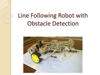
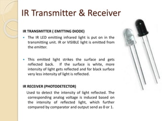
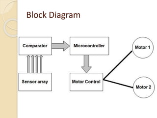
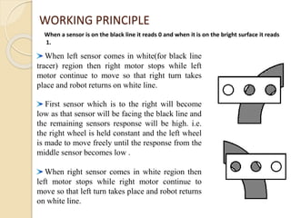
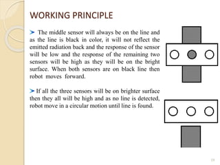
Line Following Robot with
Obstacle Detection
Objectives
 Improve knowledge of robotics as well as
microcontroller programming and electronic circuit
design and construction.
 Construct a robot which capable of following a black
line.
 Stop within safe distance of an object in its path.
 Automatically continue when object moved.
2
Application area
 Deliver Mail within an office building to another
building.
 Industrial automated equipment carriers.
 Automated cars.
 Tour guides in museums and other similar
applications.
Main Components
 PIC Microcontroller
 Voltage Comparator
 Motor Driver IC
 Voltage Regulator
 Motor
 IR Transmitter
 IR Receiver Sensors
 Battery
 Programmer
HARDWARE DESCRIPTION
PIC Microcontroller 16F72
 Program Memory : 3.5 KB
 Speed: 20 MHz clock
 Instruction cycle: 200 ns instruction cycle
 RAM: 128 Bytes
 PIN Count: 28
 No of I/O: 22
6
Microcontroller
 It is a smaller computer
 Has on-chip RAM, ROM, I/O ports...
RAM ROM
I/O
Port
Timer
Serial
COM
Port
Microcontroller
CPU
A single chip
MOTORS
The motors are run at 6v, so an effective speed of 65 rpm is
achieved, with a considerable increase in torque.
Voltage Comparator LM324
9
Motor Driver H-Bridge L293D
10
IR TRANSMITTER ( EMITTING DIODE)
 The IR LED emitting infrared light is put on in the
transmitting unit. IR or VISIBLE light is emitted from
the emitter.
 This emitted light strikes the surface and gets
reflected back. If the surface is white, more
intensity of light gets reflected and for black surface
very less intensity of light is reflected.
IR RECEIVER (PHOTODETECTOR)
Used to detect the intensity of light reflected. The
corresponding analog voltage is induced based on
the intensity of reflected light, which further
compared by comparator and output send as 0 or 1.
IR Transmitter & Receiver
Regulator IC 7805
12
 A voltage regulator is an electrical
regulator designed to automatically maintain
a constant voltage level.
It converts a positive voltage (7-29V) to
+5 volts.
Heat sink provided in the center to release
heat generated due to drop across the IC.
 Input voltage of about 5 to 18 V is given,
Ground is 0 V and regulated output of +5V.
Battery
13
Programmer
14
WORKING PROCEDURE
Block Diagram
Black Line Sensor Line Follower
© 2015 EV3Lessons.com, Last edit
9/7/2015 17
2
1
Sensor 1 on White
Sensor 2 on White
Go forward
Sensor 1 on Black
Sensor 2 on White
Turn left
Sensor 1 on White
Sensor 2 on Black
Turn right
2
1
2
1
WORKING PRINCIPLE
When a sensor is on the black line it reads 0 and when it is on the bright surface it reads
1.
When left sensor comes in white(for black line
tracer) region then right motor stops while left
motor continue to move so that right turn takes
place and robot returns on white line.
First sensor which is to the right will become
low as that sensor will be facing the black line and
the remaining sensors response will be high. i.e.
the right wheel is held constant and the left wheel
is made to move freely until the response from the
middle sensor becomes low .
When right sensor comes in white region then
left motor stops while right motor continue to
move so that left turn takes place and robot returns
on white line.
19
The middle sensor will always be on the line and
as the line is black in color, it will not reflect the
emitted radiation back and the response of the sensor
will be low and the response of the remaining two
sensors will be high as they will be on the bright
surface. When both sensors are on black line then
robot moves forward.
If all the three sensors will be on brighter surface
then they all will be high and as no line is detected,
robot move in a circular motion until line is found.
WORKING PRINCIPLE
VARIOUS TRACKS
20
Software requirements
 MikroC for writing Program
and compiled to generate
machine file.
 Proteus for Simulating the
circuit.
 PIC Kit for input the program
files to Microcontroller.
LIMITATIONS
 Calibration is difficult and it is not easy to set a
perfect value.
 The steering mechanism is not easily
implemented in huge vehicles and impossible
for non-electric vehicles (petrol powered).
 Few curves are not made efficiently, and must
be avoided.
 External IR source is affected the sensor.
22
FUTURE SCOPE
 Software control of the line type (dark or
light) to make automatic detection
possible.
 “Obstacle detecting sensors” to avoid
physical obstacles and continue on the
line.
 Distance sensing and position logging &
find the shortest path.
23
340211628-Line-Follower-Robot-Presentation.pdf

340211628-Line-Follower-Robot-Presentation.pdf

  • 1.
    Line Following Robotwith Obstacle Detection
  • 2.
    Objectives  Improve knowledgeof robotics as well as microcontroller programming and electronic circuit design and construction.  Construct a robot which capable of following a black line.  Stop within safe distance of an object in its path.  Automatically continue when object moved. 2
  • 3.
    Application area  DeliverMail within an office building to another building.  Industrial automated equipment carriers.  Automated cars.  Tour guides in museums and other similar applications.
  • 4.
    Main Components  PICMicrocontroller  Voltage Comparator  Motor Driver IC  Voltage Regulator  Motor  IR Transmitter  IR Receiver Sensors  Battery  Programmer
  • 5.
  • 6.
    PIC Microcontroller 16F72 Program Memory : 3.5 KB  Speed: 20 MHz clock  Instruction cycle: 200 ns instruction cycle  RAM: 128 Bytes  PIN Count: 28  No of I/O: 22 6
  • 7.
    Microcontroller  It isa smaller computer  Has on-chip RAM, ROM, I/O ports... RAM ROM I/O Port Timer Serial COM Port Microcontroller CPU A single chip
  • 8.
    MOTORS The motors arerun at 6v, so an effective speed of 65 rpm is achieved, with a considerable increase in torque.
  • 9.
  • 10.
  • 11.
    IR TRANSMITTER (EMITTING DIODE)  The IR LED emitting infrared light is put on in the transmitting unit. IR or VISIBLE light is emitted from the emitter.  This emitted light strikes the surface and gets reflected back. If the surface is white, more intensity of light gets reflected and for black surface very less intensity of light is reflected. IR RECEIVER (PHOTODETECTOR) Used to detect the intensity of light reflected. The corresponding analog voltage is induced based on the intensity of reflected light, which further compared by comparator and output send as 0 or 1. IR Transmitter & Receiver
  • 12.
    Regulator IC 7805 12 A voltage regulator is an electrical regulator designed to automatically maintain a constant voltage level. It converts a positive voltage (7-29V) to +5 volts. Heat sink provided in the center to release heat generated due to drop across the IC.  Input voltage of about 5 to 18 V is given, Ground is 0 V and regulated output of +5V.
  • 13.
  • 14.
  • 15.
  • 16.
  • 17.
    Black Line SensorLine Follower © 2015 EV3Lessons.com, Last edit 9/7/2015 17 2 1 Sensor 1 on White Sensor 2 on White Go forward Sensor 1 on Black Sensor 2 on White Turn left Sensor 1 on White Sensor 2 on Black Turn right 2 1 2 1
  • 18.
    WORKING PRINCIPLE When asensor is on the black line it reads 0 and when it is on the bright surface it reads 1. When left sensor comes in white(for black line tracer) region then right motor stops while left motor continue to move so that right turn takes place and robot returns on white line. First sensor which is to the right will become low as that sensor will be facing the black line and the remaining sensors response will be high. i.e. the right wheel is held constant and the left wheel is made to move freely until the response from the middle sensor becomes low . When right sensor comes in white region then left motor stops while right motor continue to move so that left turn takes place and robot returns on white line.
  • 19.
    19 The middle sensorwill always be on the line and as the line is black in color, it will not reflect the emitted radiation back and the response of the sensor will be low and the response of the remaining two sensors will be high as they will be on the bright surface. When both sensors are on black line then robot moves forward. If all the three sensors will be on brighter surface then they all will be high and as no line is detected, robot move in a circular motion until line is found. WORKING PRINCIPLE
  • 20.
  • 21.
    Software requirements  MikroCfor writing Program and compiled to generate machine file.  Proteus for Simulating the circuit.  PIC Kit for input the program files to Microcontroller.
  • 22.
    LIMITATIONS  Calibration isdifficult and it is not easy to set a perfect value.  The steering mechanism is not easily implemented in huge vehicles and impossible for non-electric vehicles (petrol powered).  Few curves are not made efficiently, and must be avoided.  External IR source is affected the sensor. 22
  • 23.
    FUTURE SCOPE  Softwarecontrol of the line type (dark or light) to make automatic detection possible.  “Obstacle detecting sensors” to avoid physical obstacles and continue on the line.  Distance sensing and position logging & find the shortest path. 23