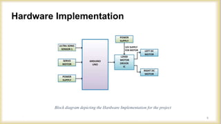
ARDUINO BASED OBSTACLE AVOIDING
ROBOTIC CAR
ARDUINO BASED OBSTACLE AVOIDING ROBOTIC CAR
7th semester Minor project
Session:2019-2023
January, 2023
PresentedBy:
2
Name Registration Roll
Abhishek Sharma 19103150017 191014
Rishabh Jha 20103150920 20(LE)EE14
Ankur Mishra 19103150010 191003
Chandra Bhushan 19103150022 191021
Government Engineering College Madhubani
Department of Electrical Engineering
Coordinated & Supervised By: Prof. Vikash Koundilya, Electrical Department, G.E.C Madhubani.
Contents
3
Title Page
Introduction
Objectives
Block Diagram
Block Diagram Overview
Hardware Implementation
Major components and its description
1: Arduino Uno
2: Motor Shield
3: Ultrasonic Sensor
4: Micro Servo
5: DC Motors
6: 9v Battery (Carbon-Zinc)
The Algorithm/ Flowchart
Working
Advantages
Limitations
Future works
Conclusion
References
Introduction
4
Introduction to the project
Our project is an Arduino based obstacle avoiding robotic car, which is a
smart car capable of detecting and avoiding obstacles in its path. This car
can move in any direction without human intervention, making it ideal
for use in a variety of situations.
5
The main goal of our project is to design and build a smart robotic car that
can detect and avoid obstacles in its path. We aim to achieve this goal by
utilizing a range of sensors, motors, and other components, which are
controlled by an Arduino board. We also aim to demonstrate the practical
applications of our project and its potential for future development.
Goals and objectives of the project:
Objectives
Block Diagram
6
Block Diagram Overview
7
•The schematics for the Arduino-based obstacle avoiding robotic car include various
components and their connections to the Arduino Uno board.
•These components include ultrasonic sensors, motor driver module, motors, power
supply, and the Arduino Uno board itself.
•The ultrasonic sensors are connected to the digital input/output pins of the Arduino
board, while the motor driver module is connected to the PWM pins.
•The motors are connected to the motor driver module, and the power supply provides
power to the entire circuit.
•The connections between the components are made using jumper wires and are carefully
placed on a breadboard or a custom PCB for better organization and stability.
•The schematics serve as a visual guide to building the robotic car, and they ensure that
the connections between the components are correct and optimized for the best
performance.
Hardware Implementation
Block diagram depicting the Hardware Implementation for the project
8
Major components and its description
9
1: Arduino Uno
USB interface chip
Crystal oscillator
Description
Arduino Uno (Continued)
Massimo Banzi David Cuartielles
10
•USB plug for uploading code and powering the board
•External power supply for additional power with regulated voltage of 9 to 12 volts
•Reset button for resetting the Arduino
•Microcontroller for receiving and sending information to the circuit
•Analog pins (A0-A5) for analog input
•Digital I/O pins (2-13) for digital input and output
•In-circuit programmer for uploading or programming code
•Digital and analog ground pins
•Power pins (3.3 and 5 volts) for powering components
•Arduino Integrated Development Environment (IDE) for writing and uploading code
Arduino Uno (Continued)
Arduino Uno Pins and Internal Components
11
⮚ Bootloader firmware preinstalled with Uno
⮚ Allows you to upload new sketches via USB
⮚ Can also use external programmer to upload sketches via the In-circuit serial programmer
(ICSP) pins
⮚ Uno Memory
• 32KB of Flash memory (Sketches stored here)
• 2KB of SRAM (variables stored until power cycled)
• 1KB of EEPROM (store long term info: calibration constants, serial #, etc.)
Arduino Uno (Continued)
Overview
12
2: Motor Shield
An Arduino Motor Shield is a shield that
allows an Arduino board to control
motors. It is a device that can be plugged
on top of an Arduino board, and it
provides an easy way to control motors
without having to write complex code or
use a separate motor controller. Motor
shields typically have connectors for
controlling DC motors, stepper motors,
and servo motors. Our motor shield has
L293D IC.
13
Motor Shield Parts Description
Motor Shield (Continued)
14
3: Ultrasonic Sensor
15
An ultrasonic sensor is a device that uses
ultrasonic waves to measure distance or
detect objects. It consists of a transmitter
that sends out ultrasonic waves, and a
receiver that listens for the reflected
waves. By measuring the time it takes for
the waves to travel to an object and back,
the sensor can calculate the distance to
the object. We have used HC-SR04
Model.
Ultrasonic Sensor Overview
Diagram of the basic ultrasonic sensor operation
Ø What is an ultrasonic?
• ULTRA = BEYOND
• SONIC = SOUND The sound beyond
human hearing range(20000Hz) is known
as ultrasonic.
Ø What is Ultrasonic sensor?
• Ultrasonic sensors are sensors that
convert ultrasound waves to electrical
signals or vice versa.
Ultrasonic Sensor (Continued)
16
HC-SR04 Ultrasonic Sensor – Features
⮚ Power Supply: +5V DC
⮚ Quiescent Current: <2mA
⮚ Working Current: 15mA
⮚ Effectual Angle: <15°
⮚ Ranging Distance: 2cm – 400 cm/1″– 13ft
⮚ Resolution: 0.3 cm
⮚ Measuring Angle: 30 degrees
⮚ Trigger Input Pulse width: 10uS
⮚ Dimension : 45mm x 20mm x 15mm
Ultrasonic Sensor (Continued)
17
HC-SR04 Ultrasonic Sensor Pin Configuration
Ultrasonic Sensor Pins
Pin
Number
Pin Name Description
1 VCC
The VCC pin powers the sensor, typically
with +5V
2 Trigger
Trigger pin is an Input pin. This pin has to
be kept high for 10us to initialize
measurement by sending US wave.
3 Echo
Echo pin is an Output pin. This pin goes
high for a period of time which will be
equal to the time taken for the US wave to
return back to the sensor.
4 Ground
This pin is connected to the Ground of the
system.
Ultrasonic Sensor (Continued)
18
HC-SR04 Ultrasonic Sensor – Working
Block Diagram of Ultrasonic Sensor working
The ultrasonic sensor uses sonar to
determine the distance to an object.
Here’s what happens:
• the transmitter
(trig pin) sends a
signal: a high-
frequency sound
• when the signal
finds an object, it
is reflected and
• the transmitter
(echo pin)
receives it.
Ultrasonic Sensor (Continued)
19
4: Micro Servo
A micro servo is a small, lightweight
servo motor that is commonly used in
robotics and other applications where
precise control of a small mechanism is
required. Servo motors are rotary
actuators that allow for precise control of
angular position, velocity, and
acceleration. They consist of a motor, a
gear train, and a feedback circuit that
allows the motor to rotate to a specific
position and hold that position.
20
Servo Mechanism
It consists of three parts:
• Controlled device
• Output sensor
• Feedback system
It is a closed loop system where it uses
positive feedback system to control
motion and final position of the shaft.
Here the device is controlled by a
feedback signal generated by comparing
output signal and reference input signal.
diagram of Servo Closed Loop System
Micro Servo (Continued)
21
Servo System
22
Turning function by servo motor to detect obstacles
•The autonomous robot (auto mode) has 5
statuses: move forward, stop, move backward,
scan right and left, and turn right or left.
•Only 1 distance sensor is used in this project,
so the sensor must have the capability to turn
around to scan for an alternative way to move.
•The sensor is attached together with a servo,
which allows the servo shaft to turn in 180
degrees to help the sensor scan the obstacle
around and choose the clear path to move
along.
•A homemade bracket is used to attach the
sensor to the servo.
Micro Servo (Continued)
5: DC Motors
A DC motor is an electric motor that runs
on direct current (DC) electricity. It
consists of a motor body, which contains
a rotating armature or rotor, and a
stationary stator that provides the
magnetic field.
23
Working of DC Motor
1.DC motors convert electrical energy into
mechanical energy through the interaction between
a magnetic field and an electric current.
2.The basic components of a DC motor include a
rotor (the rotating part) and a stator (the stationary
part).
3.The stator consists of a permanent magnet or an
electromagnet that produces a magnetic field.
4.The rotor contains a coil of wire (the armature)
that is connected to a power source through a
commutator and brushes.
5.When current flows through the armature, a
magnetic field is produced that interacts with the
stator's magnetic field, causing the rotor to rotate.
DC Motors (Continued)
24
Working of DC Motor (Continued)
6. The commutator and brushes allow the direction
of the current in the armature to change as the rotor
turns, ensuring a continuous rotation.
7. The speed and torque of the motor can be
controlled by adjusting the amount of current
supplied to the armature and the strength of the
magnetic field in the stator.
8. DC motors are widely used in many
applications, including electric vehicles,
robotics, and industrial machinery, due to their
high efficiency, controllability, and reliability.
DC Motors (Continued)
25
6: 9v Battery (Carbon-Zinc)
• A 9V battery is a type of dry cell
battery that is commonly used in
small electronic devices. It is a
single cell battery with a nominal
voltage of 9 volts.
• 9V batteries are generally more
expensive and have a shorter
lifespan than larger, higher
capacity batteries, but they are
convenient for use in small,
portable devices.
26
27
The Algorithm/ Flowchart
Working
Here is a step-by-step explanation of the working of our car:
1.The ultrasonic sensor sends out ultrasonic waves to detect obstacles in the path of the car.
2.The Arduino board receives the signal from the ultrasonic sensor and calculates the
distance to the obstacle.
3.If an obstacle is detected, the Arduino board sends a signal to the motor driver to stop the
car.
4.The Arduino board then sends a signal to the DC motors to turn the car in a different
direction.
5.The car continues moving in the new direction until it detects another obstacle.
6.This process continues until the car has reached its destination or the task is completed.
28
Advantages
 Obstacle avoiding robots can be used in almost all mobile robot
navigation systems.
 They can be used for household work like automatic vacuum
cleaning.
 They can also be used in dangerous environments, where human
penetration could be fatal.
29
Limitations
Design and programming
Rotation Issues
Hilly and rough road
30
Future Works
Adding a Camera Use as a firefighting robot DTMF GSM Based car for long range
31
Click to edit master text style
Conclusion
This autonomous robot is designed with five different modes of operation:
moving forward, stopping, moving backward, scanning to the right and left,
and turning right or left. In order to accomplish this, the robot utilizes a single
distance sensor that must have the ability to turn around and scan for
alternative paths to move.
This is achieved by attaching the sensor to a servo, which can turn the sensor
around 180 degrees to effectively scan the area for obstacles and choose the
clearest path for the robot to move along. A homemade bracket is utilized to
attach the sensor to the servo, allowing for greater precision and control over
the scanning process.
32
References
• https://www.Arduino.cc
• www.Wikipedia.org
• Google scholar
• N. Senthil Kumar,M.Saravanan,S Jeebananthan ,“Microprocessors &
Microcontrollers”, Oxford University Press,4th Edition,2012,ISBN:978-0- 19-
806647-7
• Vision-based obstacles detection for a mobile robot ElHalawany, B.M.; Abdel-
Kader, H.M.; TagEldeen, A.; Ahmed, A.E.S.; Nossair, Z.B. Informatics and
Systems (INFOS), 2012 8th International Conference on Year: 2012
• Arduino Step by Step Book
33
Arduino Based Project.pptx

Arduino Based Project.pptx

  • 1.
    ARDUINO BASED OBSTACLEAVOIDING ROBOTIC CAR
  • 2.
    ARDUINO BASED OBSTACLEAVOIDING ROBOTIC CAR 7th semester Minor project Session:2019-2023 January, 2023 PresentedBy: 2 Name Registration Roll Abhishek Sharma 19103150017 191014 Rishabh Jha 20103150920 20(LE)EE14 Ankur Mishra 19103150010 191003 Chandra Bhushan 19103150022 191021 Government Engineering College Madhubani Department of Electrical Engineering Coordinated & Supervised By: Prof. Vikash Koundilya, Electrical Department, G.E.C Madhubani.
  • 3.
    Contents 3 Title Page Introduction Objectives Block Diagram BlockDiagram Overview Hardware Implementation Major components and its description 1: Arduino Uno 2: Motor Shield 3: Ultrasonic Sensor 4: Micro Servo 5: DC Motors 6: 9v Battery (Carbon-Zinc) The Algorithm/ Flowchart Working Advantages Limitations Future works Conclusion References
  • 4.
    Introduction 4 Introduction to theproject Our project is an Arduino based obstacle avoiding robotic car, which is a smart car capable of detecting and avoiding obstacles in its path. This car can move in any direction without human intervention, making it ideal for use in a variety of situations.
  • 5.
    5 The main goalof our project is to design and build a smart robotic car that can detect and avoid obstacles in its path. We aim to achieve this goal by utilizing a range of sensors, motors, and other components, which are controlled by an Arduino board. We also aim to demonstrate the practical applications of our project and its potential for future development. Goals and objectives of the project: Objectives
  • 6.
  • 7.
    Block Diagram Overview 7 •Theschematics for the Arduino-based obstacle avoiding robotic car include various components and their connections to the Arduino Uno board. •These components include ultrasonic sensors, motor driver module, motors, power supply, and the Arduino Uno board itself. •The ultrasonic sensors are connected to the digital input/output pins of the Arduino board, while the motor driver module is connected to the PWM pins. •The motors are connected to the motor driver module, and the power supply provides power to the entire circuit. •The connections between the components are made using jumper wires and are carefully placed on a breadboard or a custom PCB for better organization and stability. •The schematics serve as a visual guide to building the robotic car, and they ensure that the connections between the components are correct and optimized for the best performance.
  • 8.
    Hardware Implementation Block diagramdepicting the Hardware Implementation for the project 8
  • 9.
    Major components andits description 9 1: Arduino Uno USB interface chip Crystal oscillator
  • 10.
  • 11.
    •USB plug foruploading code and powering the board •External power supply for additional power with regulated voltage of 9 to 12 volts •Reset button for resetting the Arduino •Microcontroller for receiving and sending information to the circuit •Analog pins (A0-A5) for analog input •Digital I/O pins (2-13) for digital input and output •In-circuit programmer for uploading or programming code •Digital and analog ground pins •Power pins (3.3 and 5 volts) for powering components •Arduino Integrated Development Environment (IDE) for writing and uploading code Arduino Uno (Continued) Arduino Uno Pins and Internal Components 11
  • 12.
    ⮚ Bootloader firmwarepreinstalled with Uno ⮚ Allows you to upload new sketches via USB ⮚ Can also use external programmer to upload sketches via the In-circuit serial programmer (ICSP) pins ⮚ Uno Memory • 32KB of Flash memory (Sketches stored here) • 2KB of SRAM (variables stored until power cycled) • 1KB of EEPROM (store long term info: calibration constants, serial #, etc.) Arduino Uno (Continued) Overview 12
  • 13.
    2: Motor Shield AnArduino Motor Shield is a shield that allows an Arduino board to control motors. It is a device that can be plugged on top of an Arduino board, and it provides an easy way to control motors without having to write complex code or use a separate motor controller. Motor shields typically have connectors for controlling DC motors, stepper motors, and servo motors. Our motor shield has L293D IC. 13
  • 14.
    Motor Shield PartsDescription Motor Shield (Continued) 14
  • 15.
    3: Ultrasonic Sensor 15 Anultrasonic sensor is a device that uses ultrasonic waves to measure distance or detect objects. It consists of a transmitter that sends out ultrasonic waves, and a receiver that listens for the reflected waves. By measuring the time it takes for the waves to travel to an object and back, the sensor can calculate the distance to the object. We have used HC-SR04 Model.
  • 16.
    Ultrasonic Sensor Overview Diagramof the basic ultrasonic sensor operation Ø What is an ultrasonic? • ULTRA = BEYOND • SONIC = SOUND The sound beyond human hearing range(20000Hz) is known as ultrasonic. Ø What is Ultrasonic sensor? • Ultrasonic sensors are sensors that convert ultrasound waves to electrical signals or vice versa. Ultrasonic Sensor (Continued) 16
  • 17.
    HC-SR04 Ultrasonic Sensor– Features ⮚ Power Supply: +5V DC ⮚ Quiescent Current: <2mA ⮚ Working Current: 15mA ⮚ Effectual Angle: <15° ⮚ Ranging Distance: 2cm – 400 cm/1″– 13ft ⮚ Resolution: 0.3 cm ⮚ Measuring Angle: 30 degrees ⮚ Trigger Input Pulse width: 10uS ⮚ Dimension : 45mm x 20mm x 15mm Ultrasonic Sensor (Continued) 17
  • 18.
    HC-SR04 Ultrasonic SensorPin Configuration Ultrasonic Sensor Pins Pin Number Pin Name Description 1 VCC The VCC pin powers the sensor, typically with +5V 2 Trigger Trigger pin is an Input pin. This pin has to be kept high for 10us to initialize measurement by sending US wave. 3 Echo Echo pin is an Output pin. This pin goes high for a period of time which will be equal to the time taken for the US wave to return back to the sensor. 4 Ground This pin is connected to the Ground of the system. Ultrasonic Sensor (Continued) 18
  • 19.
    HC-SR04 Ultrasonic Sensor– Working Block Diagram of Ultrasonic Sensor working The ultrasonic sensor uses sonar to determine the distance to an object. Here’s what happens: • the transmitter (trig pin) sends a signal: a high- frequency sound • when the signal finds an object, it is reflected and • the transmitter (echo pin) receives it. Ultrasonic Sensor (Continued) 19
  • 20.
    4: Micro Servo Amicro servo is a small, lightweight servo motor that is commonly used in robotics and other applications where precise control of a small mechanism is required. Servo motors are rotary actuators that allow for precise control of angular position, velocity, and acceleration. They consist of a motor, a gear train, and a feedback circuit that allows the motor to rotate to a specific position and hold that position. 20
  • 21.
    Servo Mechanism It consistsof three parts: • Controlled device • Output sensor • Feedback system It is a closed loop system where it uses positive feedback system to control motion and final position of the shaft. Here the device is controlled by a feedback signal generated by comparing output signal and reference input signal. diagram of Servo Closed Loop System Micro Servo (Continued) 21
  • 22.
    Servo System 22 Turning functionby servo motor to detect obstacles •The autonomous robot (auto mode) has 5 statuses: move forward, stop, move backward, scan right and left, and turn right or left. •Only 1 distance sensor is used in this project, so the sensor must have the capability to turn around to scan for an alternative way to move. •The sensor is attached together with a servo, which allows the servo shaft to turn in 180 degrees to help the sensor scan the obstacle around and choose the clear path to move along. •A homemade bracket is used to attach the sensor to the servo. Micro Servo (Continued)
  • 23.
    5: DC Motors ADC motor is an electric motor that runs on direct current (DC) electricity. It consists of a motor body, which contains a rotating armature or rotor, and a stationary stator that provides the magnetic field. 23
  • 24.
    Working of DCMotor 1.DC motors convert electrical energy into mechanical energy through the interaction between a magnetic field and an electric current. 2.The basic components of a DC motor include a rotor (the rotating part) and a stator (the stationary part). 3.The stator consists of a permanent magnet or an electromagnet that produces a magnetic field. 4.The rotor contains a coil of wire (the armature) that is connected to a power source through a commutator and brushes. 5.When current flows through the armature, a magnetic field is produced that interacts with the stator's magnetic field, causing the rotor to rotate. DC Motors (Continued) 24
  • 25.
    Working of DCMotor (Continued) 6. The commutator and brushes allow the direction of the current in the armature to change as the rotor turns, ensuring a continuous rotation. 7. The speed and torque of the motor can be controlled by adjusting the amount of current supplied to the armature and the strength of the magnetic field in the stator. 8. DC motors are widely used in many applications, including electric vehicles, robotics, and industrial machinery, due to their high efficiency, controllability, and reliability. DC Motors (Continued) 25
  • 26.
    6: 9v Battery(Carbon-Zinc) • A 9V battery is a type of dry cell battery that is commonly used in small electronic devices. It is a single cell battery with a nominal voltage of 9 volts. • 9V batteries are generally more expensive and have a shorter lifespan than larger, higher capacity batteries, but they are convenient for use in small, portable devices. 26
  • 27.
  • 28.
    Working Here is astep-by-step explanation of the working of our car: 1.The ultrasonic sensor sends out ultrasonic waves to detect obstacles in the path of the car. 2.The Arduino board receives the signal from the ultrasonic sensor and calculates the distance to the obstacle. 3.If an obstacle is detected, the Arduino board sends a signal to the motor driver to stop the car. 4.The Arduino board then sends a signal to the DC motors to turn the car in a different direction. 5.The car continues moving in the new direction until it detects another obstacle. 6.This process continues until the car has reached its destination or the task is completed. 28
  • 29.
    Advantages  Obstacle avoidingrobots can be used in almost all mobile robot navigation systems.  They can be used for household work like automatic vacuum cleaning.  They can also be used in dangerous environments, where human penetration could be fatal. 29
  • 30.
    Limitations Design and programming RotationIssues Hilly and rough road 30
  • 31.
    Future Works Adding aCamera Use as a firefighting robot DTMF GSM Based car for long range 31
  • 32.
    Click to editmaster text style Conclusion This autonomous robot is designed with five different modes of operation: moving forward, stopping, moving backward, scanning to the right and left, and turning right or left. In order to accomplish this, the robot utilizes a single distance sensor that must have the ability to turn around and scan for alternative paths to move. This is achieved by attaching the sensor to a servo, which can turn the sensor around 180 degrees to effectively scan the area for obstacles and choose the clearest path for the robot to move along. A homemade bracket is utilized to attach the sensor to the servo, allowing for greater precision and control over the scanning process. 32
  • 33.
    References • https://www.Arduino.cc • www.Wikipedia.org •Google scholar • N. Senthil Kumar,M.Saravanan,S Jeebananthan ,“Microprocessors & Microcontrollers”, Oxford University Press,4th Edition,2012,ISBN:978-0- 19- 806647-7 • Vision-based obstacles detection for a mobile robot ElHalawany, B.M.; Abdel- Kader, H.M.; TagEldeen, A.; Ahmed, A.E.S.; Nossair, Z.B. Informatics and Systems (INFOS), 2012 8th International Conference on Year: 2012 • Arduino Step by Step Book 33