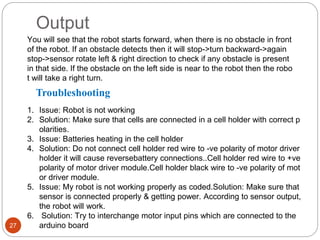
1
Project Members:
• K.Harsha Vardhan (20351-EE-012)
• R.Hima Ruthvik (20351-EE-013)
• T.Krishna Sai (20351-EE-016)
• D.Lalitesh (20351-EE-017)
Under The Esteemed
Guidence of:
Mr.S.Ravikanth (Mtech)
Multifunctional Robot Using Arduino Uno
11/12/2022
2
Objective
The main objective of this project is to make a user friendly easily portable
multifunctional robot for carrying goods,helping for old-age people,spy etc..
3
CONTENTS
 Line Following Robot
• Circuit Diagram
• Procedure
• Code
• Output
• Trouble shooting
 Obstacle Avoiding Robot
• Circuit Diagram
• Procedure
• Code
• Output
• Trouble shooting
 Maze Solving Robot
• Circuit Diagram
• Procedure
• Code
• Output
• Trouble shooting
 Edge Avoiding Robot
• Circuit Diagram
• Procedure
• Code
• Output
• Trouble shooting
11/12/2022
4
Working Model Image
Working Model Image
5
6
Components Required:
1) LDR
An LDR is a component that has a (variable) resistance that changes with t
he light intensity that falls upon it. This allows them to be used in light sensi
ng circuits. They are made of high resistance semiconductor material. Whe
n light hits the device, the photons give electrons energy. This makes them
jump into the conductive band and thereby conduct electricity.LDRs are oft
en used in circuits where it is necessary to detect the presence or the level
of light. They can be described by a variety of names from light dependent r
esistor, LDR, photoresistor, or even photocell or photoconductor. A Light S
ensor is something that a robot can use to detect the current ambient light l
evel - i.e. how bright/dark it is.
7
2) Servo Motor
A servo motor is a type of motor that can rotate with great precision. If you want
to rotate an object at some specific angles or distance, then you use a servo
motor. It is just made up of a simple motor which runs through a servo mechani
sm. A servo motor usually comes with a gear arrangement that allows us to get
a very high torque servo motor in small and lightweight packages. Due to these
features, they are being used in many applications like toy cars, RC helicopters
and planes, Robotics etc.
8
3) Ultra Sonic Sensor
An ultrasonic sensor is an electronic device that is used to measure the distance of
an object by emitting ultrasonic sound waves. It converts the reflected sound wave
s into an electrical signal. This is exactly how bats navigate in the dark. A bat produ
ces ultrasonic sound waves that bounce off a wall, or an insect so the bat knows
where there is an obstruction and where there is food.
9
4) Arduino Uno
The Arduino UNO is a microcontroller board based on a removable, dual-inline-packa
ge (DIP) ATmega328 AVR microcontroller. It is a board based microcontroller (small
computer on a chip) with facilities for processing data and I/O (input and output) pins f
or receiving and sending signals to devices. It can be powered and programmed usin
g a computer or mobile phone.
10
Features of Arduino Uno:
Microcontroller: ATmega328
Operating voltage: 5 v
Input voltage (recommended): 7-12 V
Digital I/O pins: 14 (of which 6 provide PWM output)
Analog input pins: 6
DC current per I/O pin: 40 mA
DC current for 3.3V pin: 50 mA
Flash memory: 32 KB (ATmega328)
SRAM: 2 KB (ATmega328)
EEPROM: 1 KB (ATmega328)
11
5) Motor Driver
The Motor Driver is a module for motors that allows you control the working s
peed and direction of two motors simultaneously. This Motor Driver is design
ed and developed based on L293D IC. L293D is a 16 Pin Motor Driver IC.
Light Following Robot
12
Circuit Diagram
13
14
1. Build a Motion Robot Activity, then keep the chassis Model as it is because
we are going to use that model in this activity as it is. We are going to add s
ensors on that module.
2. First remove batteries from the cell holder holder/turn off the switch on the c
ell holder.
3. Connect an Arduino board to your laptop using an Arduino cable.
4. Open Arduino IDE.
5. Go to File->Examples->Sparklebox_code->Select build_a_Light_Following_
Robot
6. Go to Tools->Board->Select Arduino Uno.
7. Go to Tools->Port->Select com port(Arduino Uno).
8. Click on the upload option & wait till done Uploading.
9. Now disconnect the Arduino Board from your laptop/Desktop.
Procedure
CODE
15
#define MLa 8 //left motor 1st pin
#define MLb 9 //left motor 2nd pin
#define MRa 10 //right motor 1st pin
#define MRb 11 //right motor 2nd pin
#define left_LDR 3
#define right_LDR 4
void setup()
{
pinMode(left_LDR, INPUT);
pinMode(right_LDR, INPUT);
pinMode(Mla, OUTPUT);
pinMode(MLb, OUTPUT);
pinMode(MRa, OUTPUT);
Serial.begin(9600);
}
Void loop()
{
16
if (digitalRead(left LDR)== HIGH && digitalRead(right_LDR) == HIGH)
{
digitalWrite(MLa, LOW);
digitalWrite(MLb, LOW);
digitalWrite(MRa, LOW);
digitalWrite(MRb, LOW);
}
if (digitalRead(left_LDR)== LOW && digitalRead(right_LDR)== LOW)
{
digitalWrite(MLa, HIGH);
digitalWrite(MLb, LOW);
digitalWrite(MRa, HIGH);
digitalWrite(MRb, LOW);
}
if (digitalRead(left_LDR)== LOW && digitalRead(right_LDR) HIGH)
{
digitalWrite(MLa, LOW);
digitalWrite(MLb, LOW);
digitalWrite(MRa, HIGH);
digitalWrite(MRb, LOW);
}
}
17
Output
Turn OFF the lights in your room/surrounding area where the robot is present.
Turn ON the torchlight of your mobile phone & keep it in front of any one of the
sensors. The robot will move in that direction. Example: If the lights fall on bot
h the sensors then the robot will move in Forward direction only. Otherwise it
will stop.
Troubleshooting
Issue: Robot is not working.
Solution:
1.If not getting power check the wire connections once. Always connect
batteries with correct polarity in the cell holder, cell holder red wire should con
nect to + polarity & Black wire to the -polarity of the motor driver module.
18
Obstacle Avoder Robot
19
Circuit Diagram
20
Procedure
1. If you performed the previous buld a motion robot. Activity, then keep the
chassis model as it is because we are going to use that model in this acti
vity as it is. We are going to add only an ultrasonic sensor on that model.
2. First remove batteries from the battery holder.
3. Connect an Arduino board to your laptop using an Arduino cable
4. Open Arduino IDE.
5. Go to File->Examples->Sparklebox_code->Select build_Obstacle_Avoid
er_Robot.
6. Go to Tools->Board->Select Arduino Uno.
7. Go to Tools->Port->Select com port(Arduino).
8. Click on the verify option.
9. Click on the upload option.
10.Disconnect Arduino cable from the Arduino board.
21
Output
When the boards & sensor connections are properly done with batteries attac
hed, the robot will work immediately. Try to check the robot by putting an obje
ct in front of the sensor's eyes.
Troubleshooting
Issue: Robot is not working.
Solution:
1. Check whether you connected all batteries in the battery holder or not.
2. If batteries are connected then check whether the Arduino board is getting
power or notthrough the VIN & GND pin still power, then you need to repla
ce the batteries with new.
3. If ok then check with motor wire & sensor connections with Arduino Board.
12-Nov-22
22
Maze Solving Robot
Circuit Diagram
23
24
Procedure
1. If You performed the previous Build a Motion Robot Activity, then keep the
chassis Model as it is because we are going to use that model in this activi
ty as it is. We are going to add sensor & servo motoron that model.
2. First remove batteries from the cell holder holder.
3. Connect an Arduino board to your laptop using an Arduino cable.
4. Open Arduino IDE.
5. Go to File->Examples->Sparklebox_code->Select build_a_Maze_Solving_
Robot.
6. Go to Tools->Board->Select Arduino Uno.
7. Go to Tools->Port->Select com port(Arduino Uno).
8. Click on the upload option & wait till done Uploading.
9. Now disconnect the Arduino Board from your laptop/Desktop.
11/12/2022
25
11/12/2022
26
27
Output
You will see that the robot starts forward, when there is no obstacle in front
of the robot. If an obstacle detects then it will stop->turn backward->again
stop->sensor rotate left & right direction to check if any obstacle is present
in that side. If the obstacle on the left side is near to the robot then the robo
t will take a right turn.
Troubleshooting
1. Issue: Robot is not working
2. Solution: Make sure that cells are connected in a cell holder with correct p
olarities.
3. Issue: Batteries heating in the cell holder
4. Solution: Do not connect cell holder red wire to -ve polarity of motor driver
holder it will cause reversebattery connections..Cell holder red wire to +ve
polarity of motor driver module.Cell holder black wire to -ve polarity of mot
or driver module.
5. Issue: My robot is not working properly as coded.Solution: Make sure that
sensor is connected properly & getting power. According to sensor output,
the robot will work.
6. Solution: Try to interchange motor input pins which are connected to the
arduino board
CONCLUSION
28
Hence we completed the project of multifunctional robot
So it can be worked as :
Light Following Robot
Obstacle Avoiding Robot
Maze Solving Robot
Edge Avoiding Robot…….

Multifunctional Robot (PPT).pptx

  • 1.
    1 Project Members: • K.HarshaVardhan (20351-EE-012) • R.Hima Ruthvik (20351-EE-013) • T.Krishna Sai (20351-EE-016) • D.Lalitesh (20351-EE-017) Under The Esteemed Guidence of: Mr.S.Ravikanth (Mtech) Multifunctional Robot Using Arduino Uno
  • 2.
    11/12/2022 2 Objective The main objectiveof this project is to make a user friendly easily portable multifunctional robot for carrying goods,helping for old-age people,spy etc..
  • 3.
    3 CONTENTS  Line FollowingRobot • Circuit Diagram • Procedure • Code • Output • Trouble shooting  Obstacle Avoiding Robot • Circuit Diagram • Procedure • Code • Output • Trouble shooting  Maze Solving Robot • Circuit Diagram • Procedure • Code • Output • Trouble shooting  Edge Avoiding Robot • Circuit Diagram • Procedure • Code • Output • Trouble shooting
  • 4.
  • 5.
  • 6.
    6 Components Required: 1) LDR AnLDR is a component that has a (variable) resistance that changes with t he light intensity that falls upon it. This allows them to be used in light sensi ng circuits. They are made of high resistance semiconductor material. Whe n light hits the device, the photons give electrons energy. This makes them jump into the conductive band and thereby conduct electricity.LDRs are oft en used in circuits where it is necessary to detect the presence or the level of light. They can be described by a variety of names from light dependent r esistor, LDR, photoresistor, or even photocell or photoconductor. A Light S ensor is something that a robot can use to detect the current ambient light l evel - i.e. how bright/dark it is.
  • 7.
    7 2) Servo Motor Aservo motor is a type of motor that can rotate with great precision. If you want to rotate an object at some specific angles or distance, then you use a servo motor. It is just made up of a simple motor which runs through a servo mechani sm. A servo motor usually comes with a gear arrangement that allows us to get a very high torque servo motor in small and lightweight packages. Due to these features, they are being used in many applications like toy cars, RC helicopters and planes, Robotics etc.
  • 8.
    8 3) Ultra SonicSensor An ultrasonic sensor is an electronic device that is used to measure the distance of an object by emitting ultrasonic sound waves. It converts the reflected sound wave s into an electrical signal. This is exactly how bats navigate in the dark. A bat produ ces ultrasonic sound waves that bounce off a wall, or an insect so the bat knows where there is an obstruction and where there is food.
  • 9.
    9 4) Arduino Uno TheArduino UNO is a microcontroller board based on a removable, dual-inline-packa ge (DIP) ATmega328 AVR microcontroller. It is a board based microcontroller (small computer on a chip) with facilities for processing data and I/O (input and output) pins f or receiving and sending signals to devices. It can be powered and programmed usin g a computer or mobile phone.
  • 10.
    10 Features of ArduinoUno: Microcontroller: ATmega328 Operating voltage: 5 v Input voltage (recommended): 7-12 V Digital I/O pins: 14 (of which 6 provide PWM output) Analog input pins: 6 DC current per I/O pin: 40 mA DC current for 3.3V pin: 50 mA Flash memory: 32 KB (ATmega328) SRAM: 2 KB (ATmega328) EEPROM: 1 KB (ATmega328)
  • 11.
    11 5) Motor Driver TheMotor Driver is a module for motors that allows you control the working s peed and direction of two motors simultaneously. This Motor Driver is design ed and developed based on L293D IC. L293D is a 16 Pin Motor Driver IC.
  • 12.
  • 13.
  • 14.
    14 1. Build aMotion Robot Activity, then keep the chassis Model as it is because we are going to use that model in this activity as it is. We are going to add s ensors on that module. 2. First remove batteries from the cell holder holder/turn off the switch on the c ell holder. 3. Connect an Arduino board to your laptop using an Arduino cable. 4. Open Arduino IDE. 5. Go to File->Examples->Sparklebox_code->Select build_a_Light_Following_ Robot 6. Go to Tools->Board->Select Arduino Uno. 7. Go to Tools->Port->Select com port(Arduino Uno). 8. Click on the upload option & wait till done Uploading. 9. Now disconnect the Arduino Board from your laptop/Desktop. Procedure
  • 15.
    CODE 15 #define MLa 8//left motor 1st pin #define MLb 9 //left motor 2nd pin #define MRa 10 //right motor 1st pin #define MRb 11 //right motor 2nd pin #define left_LDR 3 #define right_LDR 4 void setup() { pinMode(left_LDR, INPUT); pinMode(right_LDR, INPUT); pinMode(Mla, OUTPUT); pinMode(MLb, OUTPUT); pinMode(MRa, OUTPUT); Serial.begin(9600); } Void loop() {
  • 16.
    16 if (digitalRead(left LDR)==HIGH && digitalRead(right_LDR) == HIGH) { digitalWrite(MLa, LOW); digitalWrite(MLb, LOW); digitalWrite(MRa, LOW); digitalWrite(MRb, LOW); } if (digitalRead(left_LDR)== LOW && digitalRead(right_LDR)== LOW) { digitalWrite(MLa, HIGH); digitalWrite(MLb, LOW); digitalWrite(MRa, HIGH); digitalWrite(MRb, LOW); } if (digitalRead(left_LDR)== LOW && digitalRead(right_LDR) HIGH) { digitalWrite(MLa, LOW); digitalWrite(MLb, LOW); digitalWrite(MRa, HIGH); digitalWrite(MRb, LOW); } }
  • 17.
    17 Output Turn OFF thelights in your room/surrounding area where the robot is present. Turn ON the torchlight of your mobile phone & keep it in front of any one of the sensors. The robot will move in that direction. Example: If the lights fall on bot h the sensors then the robot will move in Forward direction only. Otherwise it will stop. Troubleshooting Issue: Robot is not working. Solution: 1.If not getting power check the wire connections once. Always connect batteries with correct polarity in the cell holder, cell holder red wire should con nect to + polarity & Black wire to the -polarity of the motor driver module.
  • 18.
  • 19.
  • 20.
    20 Procedure 1. If youperformed the previous buld a motion robot. Activity, then keep the chassis model as it is because we are going to use that model in this acti vity as it is. We are going to add only an ultrasonic sensor on that model. 2. First remove batteries from the battery holder. 3. Connect an Arduino board to your laptop using an Arduino cable 4. Open Arduino IDE. 5. Go to File->Examples->Sparklebox_code->Select build_Obstacle_Avoid er_Robot. 6. Go to Tools->Board->Select Arduino Uno. 7. Go to Tools->Port->Select com port(Arduino). 8. Click on the verify option. 9. Click on the upload option. 10.Disconnect Arduino cable from the Arduino board.
  • 21.
    21 Output When the boards& sensor connections are properly done with batteries attac hed, the robot will work immediately. Try to check the robot by putting an obje ct in front of the sensor's eyes. Troubleshooting Issue: Robot is not working. Solution: 1. Check whether you connected all batteries in the battery holder or not. 2. If batteries are connected then check whether the Arduino board is getting power or notthrough the VIN & GND pin still power, then you need to repla ce the batteries with new. 3. If ok then check with motor wire & sensor connections with Arduino Board.
  • 22.
  • 23.
  • 24.
    24 Procedure 1. If Youperformed the previous Build a Motion Robot Activity, then keep the chassis Model as it is because we are going to use that model in this activi ty as it is. We are going to add sensor & servo motoron that model. 2. First remove batteries from the cell holder holder. 3. Connect an Arduino board to your laptop using an Arduino cable. 4. Open Arduino IDE. 5. Go to File->Examples->Sparklebox_code->Select build_a_Maze_Solving_ Robot. 6. Go to Tools->Board->Select Arduino Uno. 7. Go to Tools->Port->Select com port(Arduino Uno). 8. Click on the upload option & wait till done Uploading. 9. Now disconnect the Arduino Board from your laptop/Desktop.
  • 25.
  • 26.
  • 27.
    27 Output You will seethat the robot starts forward, when there is no obstacle in front of the robot. If an obstacle detects then it will stop->turn backward->again stop->sensor rotate left & right direction to check if any obstacle is present in that side. If the obstacle on the left side is near to the robot then the robo t will take a right turn. Troubleshooting 1. Issue: Robot is not working 2. Solution: Make sure that cells are connected in a cell holder with correct p olarities. 3. Issue: Batteries heating in the cell holder 4. Solution: Do not connect cell holder red wire to -ve polarity of motor driver holder it will cause reversebattery connections..Cell holder red wire to +ve polarity of motor driver module.Cell holder black wire to -ve polarity of mot or driver module. 5. Issue: My robot is not working properly as coded.Solution: Make sure that sensor is connected properly & getting power. According to sensor output, the robot will work. 6. Solution: Try to interchange motor input pins which are connected to the arduino board
  • 28.
    CONCLUSION 28 Hence we completedthe project of multifunctional robot So it can be worked as : Light Following Robot Obstacle Avoiding Robot Maze Solving Robot Edge Avoiding Robot…….