ESD PROJECT SYNOPSIS
LINEFOLLOWER ROBOT
Fourth Semester Electronics and Communication
Engineering
Submitted by
Samrika (230907068)
Serina Sakhare (230907084)
Aditi S Kotian (230907090)
DEPARTMENT OF ELECTRONICS AND COMMUNICATION ENGINEERING
MANIPAL INSTITUTE OF TECHNOLOGY
(A Constituent Institution of Manipal Academy of Higher Education)
MANIPAL – 576104, KARNATAKA, INDIA
JAN/MAY 2025
2.
This project focuseson the design and construction of a basic line follower robot using
fundamental electronic components and circuits. The robot is engineered to autonomously
detect and follow a predefined path, relying solely on hardware-based solutions without the
use of microprocessors or microcontrollers. The core functionality is achieved through the
integration of sensors, amplifiers, and motor driver circuits, highlighting the practical
applications of analog and digital electronics. This project is expected to provide us with an
opportunity to deepen our understanding of electronic components, circuit design, and their
role in automation. By focusing on simplicity and a purely electronics-driven approach, this
project aims to strengthen our technical knowledge and problem-solving abilities while
serving as an ideal introductory experience to robotics and sensor-based systems for
beginners in electronics.
3.
INTRODUCTION
A line followerrobot is a self-operating system designed to autonomously detect and trace a
path marked by a continuous line, usually on a contrasting surface. This simple yet powerful
robotic system is a perfect demonstration of real-time decision-making and control systems in
electronics engineering.
The working principle behind a line follower robot is based on the feedback loop between
sensors, control circuits, and motors. The robot continuously evaluates the line's position by
sensing its contrast against the surrounding surface. When the robot deviates from the line, the
sensors detect the change and send signals to the control system to adjust the motor speeds,
ensuring the robot returns to its path.
Infrared (IR) sensors are key to this navigation system. They emit infrared light towards the
surface and measure the reflected light to distinguish between light and dark areas. When the
robot is on a dark line, the IR sensors detect less reflection, while on a lighter surface, more
light is reflected. This feedback allows the robot to make corrections to its movement by
adjusting the speed and direction of the motors.
The motors used in this project are typically DC motors, which drive the wheels of the robot.
These motors are controlled via motor driver circuits, which receive inputs from the sensor
system and adjust the motors' rotation. This combination of sensors, feedback loops, and motor
control mechanisms demonstrates fundamental concepts of electronics and control systems in
autonomous robotics.
4.
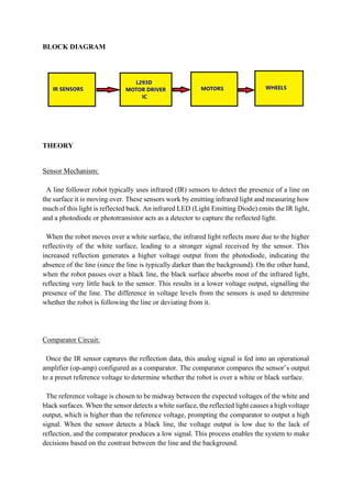
BLOCK DIAGRAM
THEORY
Sensor Mechanism:
Aline follower robot typically uses infrared (IR) sensors to detect the presence of a line on
the surface it is moving over. These sensors work by emitting infrared light and measuring how
much of this light is reflected back. An infrared LED (Light Emitting Diode) emits the IR light,
and a photodiode or phototransistor acts as a detector to capture the reflected light.
When the robot moves over a white surface, the infrared light reflects more due to the higher
reflectivity of the white surface, leading to a stronger signal received by the sensor. This
increased reflection generates a higher voltage output from the photodiode, indicating the
absence of the line (since the line is typically darker than the background). On the other hand,
when the robot passes over a black line, the black surface absorbs most of the infrared light,
reflecting very little back to the sensor. This results in a lower voltage output, signalling the
presence of the line. The difference in voltage levels from the sensors is used to determine
whether the robot is following the line or deviating from it.
Comparator Circuit:
Once the IR sensor captures the reflection data, this analog signal is fed into an operational
amplifier (op-amp) configured as a comparator. The comparator compares the sensor’s output
to a preset reference voltage to determine whether the robot is over a white or black surface.
The reference voltage is chosen to be midway between the expected voltages of the white and
black surfaces. When the sensor detects a white surface, the reflected light causes a high voltage
output, which is higher than the reference voltage, prompting the comparator to output a high
signal. When the sensor detects a black line, the voltage output is low due to the lack of
reflection, and the comparator produces a low signal. This process enables the system to make
decisions based on the contrast between the line and the background.
5.
In this way,the comparator’s output provides a binary signal—high or low—that corresponds
to whether the robot is following the line or not, based on the sensor readings.
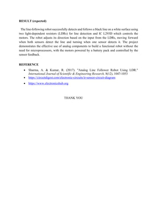
Motor Control Circuit (Using L293D):
The L293D is a dual H-Bridge motor driver IC that allows you to control the direction and
speed of two DC motors. It takes the binary output from the comparator and uses it to control
the motors’ movement. The L293D has several pins for controlling the motors:
• Input Pins (2, 7, 10, 15): These pins receive the signals from the comparators. The state
of these pins determines the direction of the motors.
• Enable Pins (1, 9): These pins control the motor’s speed. By applying a PWM signal,
you can adjust the speed of the motors.
• Motor Power Pin (8): Supplies power to the motors (usually 9V or 12V).
• Logic Power Pin (16): Supplies 5V to the internal logic of the L293D.
By adjusting the input pins according to the sensor feedback, the L293D controls the motors to
keep the robot on the line.
Feedback Loop:
The system operates in a feedback loop, where the IR sensors continuously detect the surface
under the robot. Based on the data from the sensors, the comparator generates outputs that
determine the motor behaviour through the L293D motor driver.
When the robot deviates from the line, the sensor readings will change, and the comparator
will adjust the motor control signals. This continuous feedback allows the robot to make real-
time corrections, ensuring it follows the line despite curves, turns, or changes in direction.
The motor driver, in combination with the sensor inputs and feedback from the comparator,
ensures that the robot stays on the designated path and adjusts its movement accordingly.
6.
METHODOLOGY TO BEUSED
1. Assemble the Chassis:
Build the robot chassis and place motors, sensors, and L293D IC.
2. Sensor Setup:
Position two IR sensors at the front to detect the line. Connect their outputs to the comparator
circuit.
3. Comparator Circuit:
Connect the IR sensor outputs to an op-amp comparator, set a reference voltage to distinguish
black and white surfaces, generating high or low signals.
4. Motor Control with L293D:
Connect the comparator outputs to the input pins of the L293D IC.
Power the motors using the motor power pin (pin 8) and control motor speed using the enable
pins (pins 1, 9).
Connect ground and logic power pins to the appropriate supplies.
5. Direction Control:
Based on sensor feedback, control motor direction (left or right turns) using the L293D’s input
pins.
6. Test and Calibrate:
Test the robot, adjust sensor positions and motor logic if necessary for smooth line following.
7. Refine and Optimize:
Make iterative adjustments to improve performance in following the line, including sensor
thresholds and speed.
COMPONENTS REQUIRED
1. IR Proximity Sensor
2. L293D or L293NE IC
3. BO Motor
4. Switch
5. PCB
6. Pin Header
7. Wires
8. Battery 9v
7.
9.Materials for Chassis
10.Wheels etc.
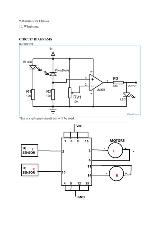
CIRCUIT DIAGRAMS
IR CIRCUIT
This is a reference circuit that will be used.
8.
RESULT (expected)
The line-followingrobot successfully detects and follows a black line on a white surface using
two light-dependent resistors (LDRs) for line detection and IC L293D which controls the
motors. The robot adjusts its direction based on the input from the LDRs, moving forward
when both sensors detect the line and turning when one sensor detects it. The project
demonstrates the effective use of analog components to build a functional robot without the
need for microprocessors, with the motors powered by a battery pack and controlled by the
sensor feedback.
REFERENCE
• Sharma, A. & Kumar, R. (2017). "Analog Line Follower Robot Using LDR."
International Journal of Scientific & Engineering Research, 8(12), 1047-1053
• https://circuitdigest.com/electronic-circuits/ir-sensor-circuit-diagram
• https://www.electronicshub.org
THANK YOU