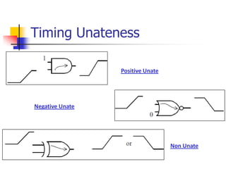
This document discusses library characterization, which involves characterizing standard cell libraries used in semiconductor design. It begins with an overview of why library characterization is an interesting career and then discusses fundamental terminology. It provides examples of characterizing an inverter and D flip-flop, covering timing analysis, power characterization, and more. Advanced topics discussed include state dependent delays, load capacitance characterization, and measuring tri-state delays. References are provided for further reading.
Clock Tree Synthesis is a technique for distributing the clock equally among all sequential parts of a VLSI design. The purpose of Clock Tree Synthesis is to reduce skew and delay. Clock Tree Synthesis is provided the placement data as well as the clock tree limitations as input. Clock Tree Synthesis (CTS) is the technique of balancing the clock delay to all clock inputs by inserting buffers/inverters along the clock routes of an ASIC design. As a result, CTS is used to balance the skew and reduce insertion latency. Before Clock Tree Synthesis, all clock pins were driven by a single clock source. Clock tree synthesis includes both clock tree construction and clock tree balance. Clock tree inverters may be used to create a clock tree that maintains the correct transition (duty cycle), and clock tree buffers (CTB) can balance the clock tree to fulfil the skew and latency requirements. To fulfil the space and power limits, fewer clock tree inverters and buffers should be employed.
This is a custom GUI, which eases fixing violations either by adding buffer, cloning or sizing. Drop down menu item is created in ICC2 layout window. Desired terminals can be selected by dragging or adding points in rectilinear fashion and desired locations can be selected for adding new buffer.
In this course, you
● Identify and apply timing arc information from a library, such as unateness, delays, and slew
● Identify cell delays from a library and calculate output slew degradation
● Use wire-load information to calculate net delays
● Identify the properties of a clock, including period, edges, and slew, and calculate the duty cycle
● Apply setup and hold checks to diagnose design violations
● Identify timing path types to calculate slack values
● Set environmental constraints, clocks constraints, and path exceptions
● Constrain a design using SDC
● Analyze reports to identify timing problems
Static Timing Analysis is a process of checking timing violation of a design by checking all possible paths under worst conditions.Any deisgn with out meeting timing requirements is undesirable.STA plays vital role in chip designing .
In electronics, crosstalk is any phenomenon by which a signal transmitted on one circuit or channel of a transmission system creates an undesired effect in another circuit or channel. Crosstalk is usually caused by undesired capacitive, inductive, or conductive coupling from one circuit or channel to another.
Crosstalk is a significant issue in structured cabling, audio electronics, integrated circuit design, wireless communication and other communications systems.
Timing and Design Closure in Physical Design Flows Olivier Coudert
A physical design flow consists of producing a production-worthy layout from a gate-level netlist subject to a set of constraints. We focus on the problems imposed by shrinking process technologies. It exposes the problems of timing closure, signal integrity, design variable dependencies, clock and power/ground routing, and design signoff. It also surveys some physical design flows, and outlines a refinement-based flow.
https://www.udemy.com/vlsi-academy
Usually, while drawing any circuit on paper, we have only one 'vdd' at the top and one 'vss' at the bottom. But on a chip, it becomes necessary to have a grid structure of power, with more than one 'vdd' and 'vss'. The concept of power grid structure would be uploaded soon. It is actually the scaling trend that drives chip designers for power grid structure.
So, this has been due for long time. May be because of tight tape out deadlines, this very important piece of Physical Design flow just got missed. And I am sure, like me, many might be curious to know what is the IEEE SPEF format, what does various attributes of SPEF file represent, etc...
As we push through lower technology nodes in the IC and chip design, the wire width goes thinner along with transistor size. This makes the wire resistance more dominant on 16nm and below technology nodes. This increasing resistance and the decreasing width of metal wires introduce many Electromigration and IR drop issues. These two issues play major roles in reducing the lifespan of an electronic device and are the causes of functionality failure in any electronic devices with lower technology nodes.
In this article, we will discuss the problems of electromigration and IR drop, and techniques to prevent the occurrence of these issues in electronic devices.
Electromigration is the gradual displacement of metal atoms in a semiconductor. It occurs when the current density is high enough to cause the drift of metal ions in the direction of the electron flow, and is characterized by the ion flux density. This density depends on the magnitude of forces that tend to hold the ions in place, i.e., the nature of the conductor, crystal size, interface and grain-boundary chemistry, and the magnitude of forces that tend to dislodge them, including the current density, temperature and mechanical stresses.
The Power supply in the chip is distributed uniformly through metal layers (Vdd & Vss) across the design. These metal layers have finite amount of resistance. When voltage is applied to this metal wires current starts flowing through the metal layers and some voltage is dropped due to that resistance of metal wires and current. this drop is called as IR drop.
The paper describes the basic of Timing analysis like setup time, hold time, delays in logic circuits, timing violations and different types of timing paths like flip-flop to flip-flop path, clock gating path, asynchronous signal path, half cycle path, flip-flop to output path, input to flip-flop path and input to output path.
• Developed standard library cells using IBM 130nm technology in Cadence Virtuoso Layout editor for inverter, nand2, nor2, xnor2, mux2:1, oai2221, aoi22, oai121 and a master-slave negative edge triggered D-flip-flop with minimum area and diffusion breaks. Constructed the schematic, performed DRC-LVS closure of layout and generated a SPICE netlist with Calibre PEX extraction of all the standard cells.
• Simulated the netlists by HSPICE, verified the correctness of its functionality and also made timing analysis of D-flip-flop setup and hold times. Generated a new Synopsys cell library using SiliconSmart ACE and a new Cadence cell library from all the standard cells.
- Designed a standard cells with gates including Inverter, two input NAND, two Input NOR, two Input XOR, 2:1 Multiplexer, AOI22, OAI3222 and D Flip Flop with minimum area & diffusion breaks by using IBM130 nm process technology.
- Involved library characterization using NCX, RTL synthesis of VHDL code of 32 bit ALU Chip design using Synopsys Design Vision.
Digital standard cell library Design flowijsrd.com
Commercial library cells are companies 'proprietary information and understandably companies usually impose certain restrictions on the access and use of their library cells. Those restrictions on commercial library cells severely hamper VLSI research and teaching activities of academia. To address the problem the goal of this paper is to discuss the development of standard cell library. This involves in creating new standard cells, layout design, simulation and verification of each standard cell and finally characterization of all cells for timing and functional properties.
A Hybrid Approach to Standard Cell Power Characterization based on PVT Indepe...Arun Joseph
Focus of this work is a hybrid approach to improve traditional library characterization performance. Traditional circuit simulation for dynamic power characterization, Contributor based approach for leakage characterization
Low Power VLSI design architecture for EDA (Electronic Design Automation) and Modern Power Estimation, Reduction and Fixing technologies including clock gating and power gating
Vlsi Design of Low Transition Low Power Test Pattern Generator Using Fault Co...iosrjce
Now a day’s highly integrated multi layer board with IC’s is virtually impossible to be accessed
physically for testing. The major problem detected during testing a circuit includes test generation and gate to
I/O pin problems. In design of any circuit, consuming low power and less hardware utilization is an important
design parameter. Therefore reliable testing methods are introduced which reduces the cost of the hardware
required and also power consumed by the device. In this project a new fault coverage test pattern generator is
generated using a linear feedback shift register called FC-LFSR which can perform fault analysis and reduces
the total power of the circuit. In this test, it generates three intermediate patterns between the random patterns
which reduces the transitional activities of primary inputs so that the switching activities inside the circuit under
test will be reduced. The test patterns generated are applied to c17 benchmark circuit, whose results with fault
coverage of the circuit being tested. The simulation for this design is performed using Xilinx ISE software using
Verilog hardware description language
Gene's law, Common gate, kernel Principal Component Analysis, ASIC Physical Design Post-Layout Verification, TSMC180nm, 0.13um IBM CMOS technology, Cadence Virtuoso, FPAA, in Spanish, Bruun E,
Design and Analysis of Sequential Elements for Low Power Clocking System with...IJERA Editor
This paper proposed the design of sequential elements for low power clocking system with low low power techniques for saving the power. Power consumption is a major bottleneck of system performance and is listed as one of the top three challenges in International Technology Roadmap for Semiconductor 2008. In practice, a large portion of the on chip power is consumed by the clock system which is made of the clock distribution network and flop-flops. In this paper, various design techniques for a low power clocking system are surveyed. Among them is an effective way to reduce capacity of the clock load by minimizing number of clocked transistors. To approach this, proposed a novel clocked pair shared flip-flop which reduces the number of local clocked transistors by approximately 40%. A 24% reduction of clock driving power is achieved. In addition, low swing and double edge clocking, can be easily incorporated into the new flip-flop to build clocking systems. As the feature size becomes smaller, shorter channel lengths result in increased sub-threshold leakage current through a transistor when it is off. Dual sleep and sleepy stack methods are proposed to avoid static power consumption; the flip flops are simulated using HSPICE.
CMOS Analog IC design by Dr GS Javed - Refresher Course - Batch 1Javed G S, PhD
Topics covered in the course
1. DC Biasing of the circuits
2. Circuits for reference voltage and current generation
-Voltage Regulator
-BGR
-LDO
-V-to-I
3. Precision Current References
4. Opamp design for Analog to digital converters
- OTA
- Buffer
- Unity Feedback OTA
- Layout design strategies – 2stage opamp + CMFB
5. Sense and Return mechanisms in Feedback circuits
- Current and Voltage circuits
6. Sub-Threshold Conduction
- Low voltage Operation
7. ADC Design and Simulation
-Near Nyquist performance of Opamp for ADC Circuits
-Spectral Analysis and No. of FFT Points for simulation
-Simulation time for performance
-Resistors – their variation and Calibration
-Switch design for S/H
-CDAC
8. On-Chip Inductors
Design and Implementation of Astable Multivibrator using 555 Timer IOSRJEEE
The 555 timer is widely used as IC timer circuit and it is the most commonly used general purpose linear integrated circuit. It can run in either one of the two modes: Monostable (one stable state) or Astable (no stable state). In the Monostable mode it can produce accurate time delays from microseconds to hours. In the Astable mode it can produce rectangular waveforms with a variable Duty cycle. The simplicity and ease with which both the multivibrator circuits can be configured around this IC is one of the main reasons for its wide use. The state of the art presented in the paper is the design and implementation of an Astable multivibrator using 555 timer IC, generating non-sinusoidal waveform in the form of Rectangular waveform as well as capacitor voltage waveform in the form of ramp waveform.
DESIGN AND PERFORMANCE ANALYSIS OF NINE STAGES CMOS BASED RING OSCILLATORVLSICS Design
This paper deals with the design and performance analysis of a ring oscillator using CMOS 45nm technology process in Cadence virtuoso environment. The design of optimal Analog and Mixed Signal (AMS) very large scale integrated circuits (VLSI) is a challenging task for the integrated circuit(IC) designer. A Ring Oscillator is an active device which is made up of odd number of NOT gates and whose output oscillates between two voltage levels representing high and low. There are a number of challenges ahead while designing the CMOS Ring Oscillator which are delay, noise and glitches. CMOS is the technology of choice for many applications, CMOS oscillators with low power, phase noise and timing jitter are highly desired. In this paper, we have designed a CMOS ring oscillator with nine stages.Previously, the researchers were unable to reduce the phase noise in ring oscillators substantially with nine stages. We have successfully reduced the phase noise to -6.4kdBc/Hz at 2GHz center frequency of oscillation.
LF Energy Webinar: Electrical Grid Modelling and Simulation Through PowSyBl -...DanBrown980551
Do you want to learn how to model and simulate an electrical network from scratch in under an hour?
Then welcome to this PowSyBl workshop, hosted by Rte, the French Transmission System Operator (TSO)!
During the webinar, you will discover the PowSyBl ecosystem as well as handle and study an electrical network through an interactive Python notebook.
PowSyBl is an open source project hosted by LF Energy, which offers a comprehensive set of features for electrical grid modelling and simulation. Among other advanced features, PowSyBl provides:
- A fully editable and extendable library for grid component modelling;
- Visualization tools to display your network;
- Grid simulation tools, such as power flows, security analyses (with or without remedial actions) and sensitivity analyses;
The framework is mostly written in Java, with a Python binding so that Python developers can access PowSyBl functionalities as well.
What you will learn during the webinar:
- For beginners: discover PowSyBl's functionalities through a quick general presentation and the notebook, without needing any expert coding skills;
- For advanced developers: master the skills to efficiently apply PowSyBl functionalities to your real-world scenarios.
Dr. Sean Tan, Head of Data Science, Changi Airport Group
Discover how Changi Airport Group (CAG) leverages graph technologies and generative AI to revolutionize their search capabilities. This session delves into the unique search needs of CAG’s diverse passengers and customers, showcasing how graph data structures enhance the accuracy and relevance of AI-generated search results, mitigating the risk of “hallucinations” and improving the overall customer journey.
A tale of scale & speed: How the US Navy is enabling software delivery from l...sonjaschweigert1
Rapid and secure feature delivery is a goal across every application team and every branch of the DoD. The Navy’s DevSecOps platform, Party Barge, has achieved:
- Reduction in onboarding time from 5 weeks to 1 day
- Improved developer experience and productivity through actionable findings and reduction of false positives
- Maintenance of superior security standards and inherent policy enforcement with Authorization to Operate (ATO)
Development teams can ship efficiently and ensure applications are cyber ready for Navy Authorizing Officials (AOs). In this webinar, Sigma Defense and Anchore will give attendees a look behind the scenes and demo secure pipeline automation and security artifacts that speed up application ATO and time to production.
We will cover:
- How to remove silos in DevSecOps
- How to build efficient development pipeline roles and component templates
- How to deliver security artifacts that matter for ATO’s (SBOMs, vulnerability reports, and policy evidence)
- How to streamline operations with automated policy checks on container images
Observability Concepts EVERY Developer Should Know -- DeveloperWeek Europe.pdfPaige Cruz
Monitoring and observability aren’t traditionally found in software curriculums and many of us cobble this knowledge together from whatever vendor or ecosystem we were first introduced to and whatever is a part of your current company’s observability stack.
While the dev and ops silo continues to crumble….many organizations still relegate monitoring & observability as the purview of ops, infra and SRE teams. This is a mistake - achieving a highly observable system requires collaboration up and down the stack.
I, a former op, would like to extend an invitation to all application developers to join the observability party will share these foundational concepts to build on:
Climate Impact of Software Testing at Nordic Testing DaysKari Kakkonen
My slides at Nordic Testing Days 6.6.2024
Climate impact / sustainability of software testing discussed on the talk. ICT and testing must carry their part of global responsibility to help with the climat warming. We can minimize the carbon footprint but we can also have a carbon handprint, a positive impact on the climate. Quality characteristics can be added with sustainability, and then measured continuously. Test environments can be used less, and in smaller scale and on demand. Test techniques can be used in optimizing or minimizing number of tests. Test automation can be used to speed up testing.
Securing your Kubernetes cluster_ a step-by-step guide to success !KatiaHIMEUR1
Today, after several years of existence, an extremely active community and an ultra-dynamic ecosystem, Kubernetes has established itself as the de facto standard in container orchestration. Thanks to a wide range of managed services, it has never been so easy to set up a ready-to-use Kubernetes cluster.
However, this ease of use means that the subject of security in Kubernetes is often left for later, or even neglected. This exposes companies to significant risks.
In this talk, I'll show you step-by-step how to secure your Kubernetes cluster for greater peace of mind and reliability.
Threats to mobile devices are more prevalent and increasing in scope and complexity. Users of mobile devices desire to take full advantage of the features
available on those devices, but many of the features provide convenience and capability but sacrifice security. This best practices guide outlines steps the users can take to better protect personal devices and information.
Encryption in Microsoft 365 - ExpertsLive Netherlands 2024Albert Hoitingh
In this session I delve into the encryption technology used in Microsoft 365 and Microsoft Purview. Including the concepts of Customer Key and Double Key Encryption.
Generative AI Deep Dive: Advancing from Proof of Concept to ProductionAggregage
Join Maher Hanafi, VP of Engineering at Betterworks, in this new session where he'll share a practical framework to transform Gen AI prototypes into impactful products! He'll delve into the complexities of data collection and management, model selection and optimization, and ensuring security, scalability, and responsible use.
How to Get CNIC Information System with Paksim Ga.pptxdanishmna97
Pakdata Cf is a groundbreaking system designed to streamline and facilitate access to CNIC information. This innovative platform leverages advanced technology to provide users with efficient and secure access to their CNIC details.
By Design, not by Accident - Agile Venture Bolzano 2024
Library Characterization Flow
1. Library Characterization Its Impact on Semiconductor Industry & the flow Satish Kumar Grandhi (https://sites.google.com/site/satishkumargrandhi2/)
2. Let’s start off on a Funny Note Why Choose Library Characterization as a career ?? Very little manual effort, need only little extra intelligence Effort – 30% , Enjoyment – 70% ; No need to work over weekends Only one issue : Convergence (Kills u big time) Double Edged Sword; Little Chance of firing . But, Very few players in this business, no great chances of jumping around . Most Important ; It keeps your options wide open Physical Design, STA EDA Tool Development Circuit Design
3. Acknowledgements Heart Felt Thanks to Masamb Electronics, Anupam Kumar Sinha in specific Naveen Kumar Kotha (LSI Bangalore), Rachit I. Kushalappa (TI, Bangalore) & Naresh ANNE (AMD USA) Wiki, EDABoard & LTSPICE yahoo group NANGATE for providing open source 45nm STD cell library package All prof’s with US universities (You guys don’t hide your work in the internal repositories, hats off to you) Collegues @ NXP, Cypress & ST MicroElectronics Check out my weblink on Library Characterization for latest updated version of these slides & for more info Speaker guarantees no originality in this work ; It is a mix of material accumulated from various sources We are as dwarfs sitting on the shoulders of giants -- Sir Issac Newton
4. Contents Necessity & the Impact Fundamental Terminology Glancing Through .LIB Characterization Methodology Case Studies : Inverter & D-Flop Advanced Topics References
5. Two Great Laws Moore’s LawOn April 19, 1965 Moore predicted the most important law ever proposed in Semiconductors. Amdahl's law states that the performance improvement to be gained from using some faster mode of execution is limited by the fraction of the time the faster mode can be used Missing 3rd law, the NLDM law How are these related ??
10. Input Slew & Output Load Slew rate : Represents the maximum rate of change of signal Output Load : Total amount of capacitance at the output node
11. Timing - Combinational Transition Delay Time a system needs to switch between two different stable states, when responding to a stable input signal Propagation Delays Time it takes for the output signal to switch after the input signal has been applied.
12. Timing – Sequential 1 Setup & Hold Minimum time the data signal has to be present at the input pin of a memory cell before/after the write signal arrives. General Methodology employed : Binary Chop
13. Timing - Sequential 2 Recovery / Removal Minimum time delay that has to maintained between an asynchronous clear/set signal and before/after the clock of the cell is triggered. Method Used : Binary Chop
14. Timing – Sequential 3 Minimum Pulse WidthMinimum width of control signal in order for the cell to detect it. If the clock signal active period is smaller than this minimum time, you cannot be sure that the cell will have stored the input’s value properly.
16. Power – Short circuit If a path exists from power supply to ground, it results in continuous flow of current and results in static power dissipation CMOS Technology has neglible static power consumption (biggest advantage and reason as to why CMOS is so very popular).
17. Power - Dynamic Power dissipated during the charging and discharging of the output Load capacitance. Pdyn = CL * Vdd2 * f
18. Power - Leakage The power consumed by the sub threshold currents and by reverse biased diodes in a CMOS transistor Major Sources : Sub threshold condition Gate Leakage current * Check out Reference6
19. Wire Load Models /* Wire load table */ wire_load("ABC") { capacitance : 1.774000e-04; resistance : 3.571429e-03; area : 7.559700e-02; slope : 5.000000; fanout_length( 1, 1.3207 ); fanout_length( 2, 2.9813 ); fanout_length( 3, 5.1135 ); fanout_length( 4, 7.6639 ); fanout_length( 5, 10.0334 ); fanout_length( 6, 12.2296 ); fanout_length( 8, 19.3185 ); } No info on interconnect parasitic before Physical Design Attempts to predict the capacitance and resistance of nets in the absence of placement and routing information Excellent Paper : Steve Golson, "Resistance is Futile! Building Better Wireload Models" (Link)
22. Sensitization Set of logic conditions leading to transition; This logic condition setup process is called sensitization. In other words, it generates the stimulus at the cell input pins necessary to produce a simulation measurement of the desired characteristic, such as delay or slew. No simulations performed, analytically derives the functionality of the cell from Boolean expressions, truth tables, state tables, and flip-flop latch groups defined in the input library or template files.
23. Load Sharing Facility (LSF) Goal : Give many users processes "fair share" of resources (CPU, memory , ….) Commands : bjobs, bqueues, bhist, bkill, bswitch, bpause, bresume
24. How Simulator Works ?? Input Setup Sanity Check Generate .LIB (final masala) Arc List for each Cell Fetch the Results Develop Sensitization Vector’s Launch Them on LSF Create Spice Deck for each case
25. Capacitance Characterization Buffer comparison methodcalculates by comparing the output slope of three identical reference buffers. Charge calculation method monitors the total current (charge) flowing through each input pin and integrates it over a period of time
26. Power Characterization Calculates the current consumed and convert into power Find paths from input pins to outputs, look for every valid pin combination of the cell and simulate it. Plus, some input combinations don't change any output. But, results in power consumption For example: Clocks, sets, resets etc. that do not change the output because it already had the proper state Input changes without a clock change Also, Leakage power
28. .Measure (Spice Command) Prints the results of specific user defined analyses With this command you can measure rise and fall times, length of a pulse, delays, voltages, etc. ELDO - .extract Spectre – {export}???
29. CS 1 : Inverter ARCS : IN OUT Measurements : Rise, Fall Sensitization Vectors IN : 01, 10 OUT : 10, 01
32. Technology Impact Simulated a 3 Input NAND gate (all inputs set to '1') using cadence GPDK180 & NANGATE's 45nm models With shrinking gate length, the leakage current increases Ref : ITRS Roadmap 2005
33. CS 2 : D Flip Flop Consider a Asynchronous flop with set & Reset pins. Possible arcs to be characterized : Clk -> Q (delay) D -> Clk (setup & Hold) Set/ Reset -> Clk (Recovery & Removal) Power & cap characterization (Each instance is a 3 input nand gate)
40. State Dependent Delays Timing arcs depend on the state of pins other than Input & Output Multiple timing models are used to describe ‘a’ arc Consider a 2 I/P XOR Gate timing () { related_pin : "A"; when : "B"; sdf_cond : "(B == 1'b1)"; timing_sense : negative_unate; cell_fall(Timing_data_X1) { values ("0.012959,0.015005,…….. …………………………………………… timing () { related_pin : "A"; when : "!B"; sdf_cond : "(B == 1'b0)"; timing_sense : positive_unate; cell_fall(Timing_data_X1) { values ("0.036818,0.038956, …….. ……………………………………………
41. Negative Delays A large input slope and a cell that reacts either very quickly
42. Load Cap Characterization When output slew transition = Max_Slew(max_tout), the output loading = Max_load
43. Tri State Delay Measurement Cannot be measured using conventional voltage levels Measured by looking at the current through the output pin. Test Equipment consists of Current detector on the output of the tristate cell Pull-up and pull-down resistors that can be switched on/off independently
44. Measuring Normal-tri state delays Switch on both pull-up and pull-down resistors; produce a short current flows at the output pin. When the cell enters tristate mode the output pin will be isolated from the rest of the cell, the path from supply to output cut, and current through the output pin will stop. Current monitoring device detects when the value goes below a certain threshold (pre-defined) which is the required delay.
45. Tri State to High state delays Activate only the pull-down resistor Switch off the pull-down resistor Push the Circuit into Tri State Mode Enable the cell so that output rise ‘s
46. References Sung Mo Kang and Yusuf Leblebici, "CMOS Digital Integrated Circuits-Analysis and Design", Tata McGraw Hill, Third Edition, New Delhi, 2003 J. Bhasker & RakeshChadha, “Static Timing Analysis for Nanometer Designs: A Practical Approach” Jan M. Rabaey, AnanthaChandrakasan, and BorivojeNikolic, “Digital Integrated Circuits: A Design Perspective” RACHITH I. KUSHALAPPA, "AutoLibGen : An open source tool for automation of Standard Cell Library characterization for VDSM designs", M.E Thesis, NITK Surathkal, 2008 NARESH ANNE, "Design and Characterization of a standard cell library for the freePDK 45 process ", M.S Thesis, Oklahoma State University, 2010 (link)
47. References…. HSpice Simulation and Analysis Users Guide, Version Y-2006.09, Sep 2006 Synopsys NCX User guide, Version B-2008.12, December 2008 An Excellent Lecture on Leakage power & possible reduction Techniques by R. Saleh, Uni of British Columbia (Link) Nangate 45nm Open Cell Library (link) Excellent Tutorial on HSPICE (Link) LTSPICE Yahoo Group (Link) Last, but not the least, extensive knowledge I gained by interacting with Library char teams @ NXP, Cypress & ST microelectronics which can’t be put in words