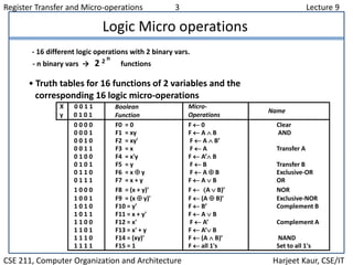
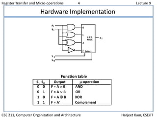
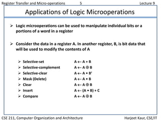
Register Transfer and Micro-operations 1 Lecture 9
CSE 211, Computer Organization and Architecture Harjeet Kaur, CSE/IT
Overview
 Register Transfer Language
 Register Transfer
 Bus and Memory Transfers
 Arithmetic Micro-operations
 Logic Micro-operations
 Shift Micro-operations
 Arithmetic Logic Shift Unit
Register Transfer and Micro-operations 2 Lecture 9
CSE 211, Computer Organization and Architecture Harjeet Kaur, CSE/IT
S1
S0
0
1
2
3
4x1
MUX
X0
Y0
C0
C1
D0
FA
S1
S0
0
1
2
3
4x1
MUX
X1
Y1
C1
C2
D1
FA
S1
S0
0
1
2
3
4x1
MUX
X2
Y2
C2
C3
D2
FA
S1
S0
0
1
2
3
4x1
MUX
X3
Y3
C3
C4
D3
FA
Cout
A0
B0
A1
B1
A2
B2
A3
B3
0 1
S0
S1
Arithmetic Circuits
S1 S0Cin Y O/P
0 0 0 B D = A + B
0 0 1 B D = A + B + 1
0 1 0 B’ D = A + B’
0 1 1 B’ D = A + B’+ 1
1 0 0 0 D = A
1 0 1 0 D = A + 1
1 1 0 1 D = A – 1
1 1 1 1 D = A
Register Transfer and Micro-operations 3 Lecture 9
CSE 211, Computer Organization and Architecture Harjeet Kaur, CSE/IT
Logic Micro operations
- 16 different logic operations with 2 binary vars.
- n binary vars → 2 2 n
functions
• Truth tables for 16 functions of 2 variables and the
corresponding 16 logic micro-operations
Boolean
Function
Micro-
Operations
Name
X 0 0 1 1
y 0 1 0 1
0 0 0 0 F0 = 0 F  0 Clear
0 0 0 1 F1 = xy F  A  B AND
0 0 1 0 F2 = xy' F  A  B’
0 0 1 1 F3 = x F  A Transfer A
0 1 0 0 F4 = x'y F  A’ B
0 1 0 1 F5 = y F  B Transfer B
0 1 1 0 F6 = x  y F  A  B Exclusive-OR
0 1 1 1 F7 = x + y F  A  B OR
1 0 0 0 F8 = (x + y)' F  A  B)’ NOR
1 0 0 1 F9 = (x  y)' F  (A  B)’ Exclusive-NOR
1 0 1 0 F10 = y' F  B’ Complement B
1 0 1 1 F11 = x + y' F  A  B
1 1 0 0 F12 = x' F  A’ Complement A
1 1 0 1 F13 = x' + y F  A’ B
1 1 1 0 F14 = (xy)' F  (A  B)’ NAND
1 1 1 1 F15 = 1 F  all 1's Set to all 1's
Register Transfer and Micro-operations 4 Lecture 9
CSE 211, Computer Organization and Architecture Harjeet Kaur, CSE/IT
Hardware Implementation
0 0 F = A  B AND
0 1 F = AB OR
1 0 F = A  B XOR
1 1 F = A’ Complement
S1 S0 Output -operation
Function table
B
A
S
S
F
1
0
i
i
i
0
1
2
3
4 X 1
MUX
Select
Register Transfer and Micro-operations 5 Lecture 9
CSE 211, Computer Organization and Architecture Harjeet Kaur, CSE/IT
Applications of Logic Microoperations
 Logic microoperations can be used to manipulate individual bits or a
portions of a word in a register
 Consider the data in a register A. In another register, B, is bit data that
will be used to modify the contents of A
 Selective-set A  A + B
 Selective-complement A  A  B
 Selective-clear A  A • B’
 Mask (Delete) A  A • B
 Clear A  A  B
 Insert A  (A • B) + C
 Compare A  A  B
Register Transfer and Micro-operations 6 Lecture 9
CSE 211, Computer Organization and Architecture Harjeet Kaur, CSE/IT
Applications of Logic Microoperations
1. In a selective set operation, the bit pattern in B is used to set certain bits in A
1 1 0 0 At
1 0 1 0 B
1 1 1 0 At+1 (A  A + B)
If a bit in B is set to 1, that same position in A gets set to 1, otherwise that
bit in A keeps its previous value
2. In a selective complement operation, the bit pattern in B is used to
complement certain bits in A
1 1 0 0 At
1 0 1 0 B
0 1 1 0 At+1 (A  A  B)
If a bit in B is set to 1, that same position in A gets complemented from its
original value, otherwise it is unchanged
Register Transfer and Micro-operations 7 Lecture 9
CSE 211, Computer Organization and Architecture Harjeet Kaur, CSE/IT
Applications of Logic Microoperations
3. In a selective clear operation, the bit pattern in B is used to clear certain bits
in A
1 1 0 0 At
1 0 1 0 B
0 1 0 0 At+1 (A  A  B’)
If a bit in B is set to 1, that same position in A gets set to 0, otherwise it is
unchanged
4. In a mask operation, the bit pattern in B is used to clear certain bits in A
1 1 0 0 At
1 0 1 0 B
1 0 0 0 At+1 (A  A  B)
If a bit in B is set to 0, that same position in A gets set to 0, otherwise it is
unchanged
Register Transfer and Micro-operations 8 Lecture 9
CSE 211, Computer Organization and Architecture Harjeet Kaur, CSE/IT
Applications of Logic Microoperations
5. In a clear operation, if the bits in the same position in A and B are the same,
they are cleared in A, otherwise they are set in A
1 1 0 0 At
1 0 1 0 B
0 1 1 0 At+1 (A  A  B)
Register Transfer and Micro-operations 9 Lecture 9
CSE 211, Computer Organization and Architecture Harjeet Kaur, CSE/IT
Applications of Logic Microoperations
6. An insert operation is used to introduce a specific bit pattern into A register,
leaving the other bit positions unchanged
This is done as
– A mask operation to clear the desired bit positions, followed by
– An OR operation to introduce the new bits into the desired positions
– Example
• Suppose you wanted to introduce 1010 into the low order four bits of A:
• 1101 1000 1011 0001 A (Original)
1101 1000 1011 1010 A (Desired)
• 1101 1000 1011 0001 A (Original)
1111 1111 1111 0000 Mask
1101 1000 1011 0000 A (Intermediate)
0000 0000 0000 1010 Added bits
1101 1000 1011 1010 A (Desired)

Lecture 9

  • 1.
    Register Transfer andMicro-operations 1 Lecture 9 CSE 211, Computer Organization and Architecture Harjeet Kaur, CSE/IT Overview  Register Transfer Language  Register Transfer  Bus and Memory Transfers  Arithmetic Micro-operations  Logic Micro-operations  Shift Micro-operations  Arithmetic Logic Shift Unit
  • 2.
    Register Transfer andMicro-operations 2 Lecture 9 CSE 211, Computer Organization and Architecture Harjeet Kaur, CSE/IT S1 S0 0 1 2 3 4x1 MUX X0 Y0 C0 C1 D0 FA S1 S0 0 1 2 3 4x1 MUX X1 Y1 C1 C2 D1 FA S1 S0 0 1 2 3 4x1 MUX X2 Y2 C2 C3 D2 FA S1 S0 0 1 2 3 4x1 MUX X3 Y3 C3 C4 D3 FA Cout A0 B0 A1 B1 A2 B2 A3 B3 0 1 S0 S1 Arithmetic Circuits S1 S0Cin Y O/P 0 0 0 B D = A + B 0 0 1 B D = A + B + 1 0 1 0 B’ D = A + B’ 0 1 1 B’ D = A + B’+ 1 1 0 0 0 D = A 1 0 1 0 D = A + 1 1 1 0 1 D = A – 1 1 1 1 1 D = A
  • 3.
    Register Transfer andMicro-operations 3 Lecture 9 CSE 211, Computer Organization and Architecture Harjeet Kaur, CSE/IT Logic Micro operations - 16 different logic operations with 2 binary vars. - n binary vars → 2 2 n functions • Truth tables for 16 functions of 2 variables and the corresponding 16 logic micro-operations Boolean Function Micro- Operations Name X 0 0 1 1 y 0 1 0 1 0 0 0 0 F0 = 0 F  0 Clear 0 0 0 1 F1 = xy F  A  B AND 0 0 1 0 F2 = xy' F  A  B’ 0 0 1 1 F3 = x F  A Transfer A 0 1 0 0 F4 = x'y F  A’ B 0 1 0 1 F5 = y F  B Transfer B 0 1 1 0 F6 = x  y F  A  B Exclusive-OR 0 1 1 1 F7 = x + y F  A  B OR 1 0 0 0 F8 = (x + y)' F  A  B)’ NOR 1 0 0 1 F9 = (x  y)' F  (A  B)’ Exclusive-NOR 1 0 1 0 F10 = y' F  B’ Complement B 1 0 1 1 F11 = x + y' F  A  B 1 1 0 0 F12 = x' F  A’ Complement A 1 1 0 1 F13 = x' + y F  A’ B 1 1 1 0 F14 = (xy)' F  (A  B)’ NAND 1 1 1 1 F15 = 1 F  all 1's Set to all 1's
  • 4.
    Register Transfer andMicro-operations 4 Lecture 9 CSE 211, Computer Organization and Architecture Harjeet Kaur, CSE/IT Hardware Implementation 0 0 F = A  B AND 0 1 F = AB OR 1 0 F = A  B XOR 1 1 F = A’ Complement S1 S0 Output -operation Function table B A S S F 1 0 i i i 0 1 2 3 4 X 1 MUX Select
  • 5.
    Register Transfer andMicro-operations 5 Lecture 9 CSE 211, Computer Organization and Architecture Harjeet Kaur, CSE/IT Applications of Logic Microoperations  Logic microoperations can be used to manipulate individual bits or a portions of a word in a register  Consider the data in a register A. In another register, B, is bit data that will be used to modify the contents of A  Selective-set A  A + B  Selective-complement A  A  B  Selective-clear A  A • B’  Mask (Delete) A  A • B  Clear A  A  B  Insert A  (A • B) + C  Compare A  A  B
  • 6.
    Register Transfer andMicro-operations 6 Lecture 9 CSE 211, Computer Organization and Architecture Harjeet Kaur, CSE/IT Applications of Logic Microoperations 1. In a selective set operation, the bit pattern in B is used to set certain bits in A 1 1 0 0 At 1 0 1 0 B 1 1 1 0 At+1 (A  A + B) If a bit in B is set to 1, that same position in A gets set to 1, otherwise that bit in A keeps its previous value 2. In a selective complement operation, the bit pattern in B is used to complement certain bits in A 1 1 0 0 At 1 0 1 0 B 0 1 1 0 At+1 (A  A  B) If a bit in B is set to 1, that same position in A gets complemented from its original value, otherwise it is unchanged
  • 7.
    Register Transfer andMicro-operations 7 Lecture 9 CSE 211, Computer Organization and Architecture Harjeet Kaur, CSE/IT Applications of Logic Microoperations 3. In a selective clear operation, the bit pattern in B is used to clear certain bits in A 1 1 0 0 At 1 0 1 0 B 0 1 0 0 At+1 (A  A  B’) If a bit in B is set to 1, that same position in A gets set to 0, otherwise it is unchanged 4. In a mask operation, the bit pattern in B is used to clear certain bits in A 1 1 0 0 At 1 0 1 0 B 1 0 0 0 At+1 (A  A  B) If a bit in B is set to 0, that same position in A gets set to 0, otherwise it is unchanged
  • 8.
    Register Transfer andMicro-operations 8 Lecture 9 CSE 211, Computer Organization and Architecture Harjeet Kaur, CSE/IT Applications of Logic Microoperations 5. In a clear operation, if the bits in the same position in A and B are the same, they are cleared in A, otherwise they are set in A 1 1 0 0 At 1 0 1 0 B 0 1 1 0 At+1 (A  A  B)
  • 9.
    Register Transfer andMicro-operations 9 Lecture 9 CSE 211, Computer Organization and Architecture Harjeet Kaur, CSE/IT Applications of Logic Microoperations 6. An insert operation is used to introduce a specific bit pattern into A register, leaving the other bit positions unchanged This is done as – A mask operation to clear the desired bit positions, followed by – An OR operation to introduce the new bits into the desired positions – Example • Suppose you wanted to introduce 1010 into the low order four bits of A: • 1101 1000 1011 0001 A (Original) 1101 1000 1011 1010 A (Desired) • 1101 1000 1011 0001 A (Original) 1111 1111 1111 0000 Mask 1101 1000 1011 0000 A (Intermediate) 0000 0000 0000 1010 Added bits 1101 1000 1011 1010 A (Desired)