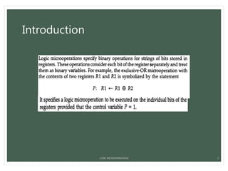
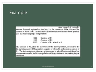
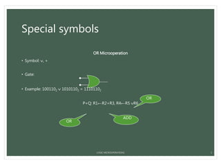
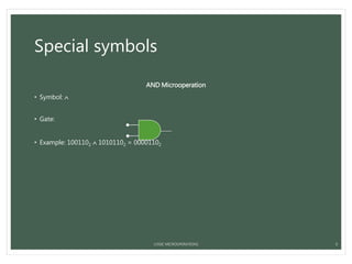
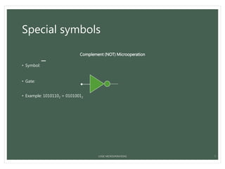
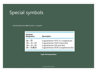
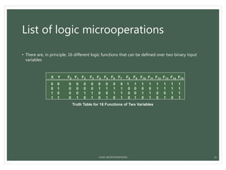
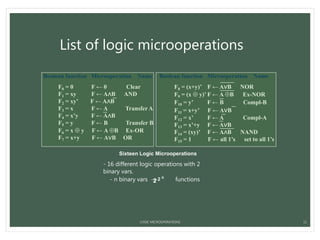
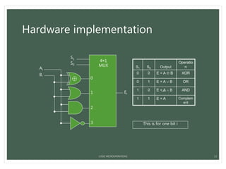
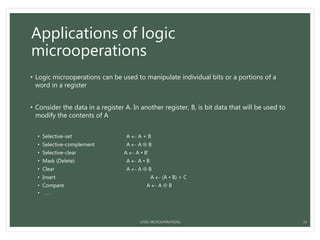
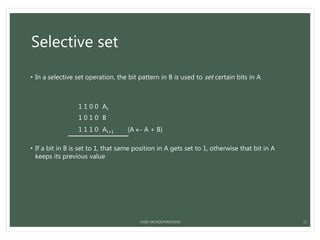
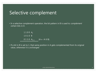
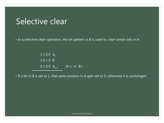
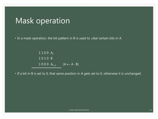
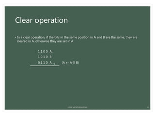
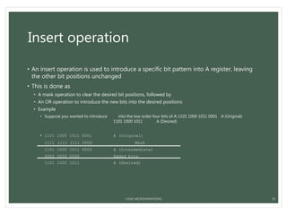
BIRLA VISHWAKARMA
MAHAVIDHYALAYA
COMPUTER ORGANIZATION AND ARCHITECTURE
Presented by: Vatsal Trivedi
LOGIC MICROOPERATIONS
1
Index
1. Introduction
2. Special symbols
3. List of logic microoperations
4. Hardware implementation
5. Applications of logic microoperations
LOGIC MICROOPERATIONS 2
Introduction
LOGIC MICROOPERATIONS 3
Example
LOGIC MICROOPERATIONS 4
Special symbols
OR Microoperation
• Symbol: , +
• Gate:
• Example: 1001102  10101102 = 11101102
P+Q: R1←R2+R3, R4←R5 R6
5
OR
OR
ADD
LOGIC MICROOPERATIONS
Special symbols
AND Microoperation
• Symbol: 
• Gate:
• Example: 1001102  10101102 = 00001102
6LOGIC MICROOPERATIONS
Special symbols
Complement (NOT) Microoperation
• Symbol:

• Gate:
• Example: 10101102 = 01010012
7LOGIC MICROOPERATIONS
Special symbols
XOR (Exclusive-OR) Microoperation
• Symbol: 
• Gate:
• Example: 1001102  10101102 = 11100002
8LOGIC MICROOPERATIONS
Special symbols
• Manipulating the bits stored in a register
Logic Microoperations
LOGIC MICROOPERATIONS 9
List of logic microoperations
• There are, in principle, 16 different logic functions that can be defined over two binary input
variables
X Y F0 F1 F2 F3 F4 F5 F6 F7 F8 F9 F10 F11 F12 F13 F14 F15
0 0 0 0 0 0 0 0 0 0 1 1 1 1 1 1 1 1
0 1 0 0 0 0 1 1 1 1 0 0 0 0 1 1 1 1
1 0 0 0 1 1 0 0 1 1 0 0 1 1 0 0 1 1
1 1 0 1 0 1 0 1 0 1 0 1 0 1 0 1 0 1
Truth Table for 16 Functions of Two Variables
LOGIC MICROOPERATIONS 10
Sixteen Logic Microoperations
Boolean function Microoperation Name
F0 = 0 F ← 0 Clear
F1 = xy F ← A∧B AND
F2 = xy’ F ← A∧B
F3 = x F ← A Transfer A
F4 = x’y F ← A∧B
F5 = y F ← B Transfer B
F6 = x  y F ← A B Ex-OR
F7 = x+y F ← A∨B OR
Boolean function Microoperation Name
F8 = (x+y)’ F ← A∨B NOR
F9 = (x  y)’ F ← A B Ex-NOR
F10 = y’ F ← B Compl-B
F11 = x+y’ F ← A∨B
F12 = x’ F ← A Compl-A
F13 = x’+y F ← A∨B
F14 = (xy)’ F ← A∧B NAND
F15 = 1 F ← all 1’s set to all 1’s
List of logic microoperations
- 16 different logic operations with 2
binary vars.
- n binary vars → functions2 2 n
LOGIC MICROOPERATIONS 11
Hardware implementation
• The hardware implementation of logic microoperations requires that logic gates be inserted for
each bit or pair of bits in the registers to perform the required logic function
• Most computers use only four (AND, OR, XOR, and NOT) from which all others can be derived.
LOGIC MICROOPERATIONS 12
Hardware implementation
S1 S0 Output
Operatio
n
0 0 E = A  B XOR
0 1 E = A  B OR
1 0 E = A  B AND
1 1 E = A Complem
ent
S1
S0
0
1
2
3
4×1
MUX
Ei
Ai
Bi
This is for one bit i
LOGIC MICROOPERATIONS 13
Applications of logic
microoperations
• Logic microoperations can be used to manipulate individual bits or a portions of a
word in a register
• Consider the data in a register A. In another register, B, is bit data that will be used to
modify the contents of A
• Selective-set A  A + B
• Selective-complement A  A  B
• Selective-clear A  A • B’
• Mask (Delete) A  A • B
• Clear A  A  B
• Insert A  (A • B) + C
• Compare A  A  B
• . . .
LOGIC MICROOPERATIONS 14
Selective set
• In a selective set operation, the bit pattern in B is used to set certain bits in A
1 1 0 0 At
1 0 1 0 B
1 1 1 0 At+1 (A  A + B)
• If a bit in B is set to 1, that same position in A gets set to 1, otherwise that bit in A
keeps its previous value
LOGIC MICROOPERATIONS 15
Selective complement
• In a selective complement operation, the bit pattern in B is used to complement
certain bits in A
1 1 0 0 At
1 0 1 0 B
0 1 1 0 At+1 (A  A  B)
• If a bit in B is set to 1, that same position in A gets complemented from its original
value, otherwise it is unchanged
LOGIC MICROOPERATIONS 16
Selective clear
• In a selective clear operation, the bit pattern in B is used to clear certain bits in A
1 1 0 0 At
1 0 1 0 B
0 1 0 0 At+1 (A  A  B’)
• If a bit in B is set to 1, that same position in A gets set to 0, otherwise it is unchanged
LOGIC MICROOPERATIONS 17
Mask operation
• In a mask operation, the bit pattern in B is used to clear certain bits in A
1 1 0 0 At
1 0 1 0 B
1 0 0 0 At+1 (A  A  B)
• If a bit in B is set to 0, that same position in A gets set to 0, otherwise it is unchanged
LOGIC MICROOPERATIONS 18
Clear operation
• In a clear operation, if the bits in the same position in A and B are the same, they are
cleared in A, otherwise they are set in A
1 1 0 0 At
1 0 1 0 B
0 1 1 0 At+1 (A  A  B)
LOGIC MICROOPERATIONS 19
Insert operation
• An insert operation is used to introduce a specific bit pattern into A register, leaving
the other bit positions unchanged
• This is done as
• A mask operation to clear the desired bit positions, followed by
• An OR operation to introduce the new bits into the desired positions
• Example
• Suppose you wanted to introduce 1010 into the low order four bits of A:1101 1000 1011 0001 A (Original)
1101 1000 1011 1010 A (Desired)
• 1101 1000 1011 0001 A (Original)
1111 1111 1111 0000 Mask
1101 1000 1011 0000 A (Intermediate)
0000 0000 0000 1010 Added bits
1101 1000 1011 1010 A (Desired)
LOGIC MICROOPERATIONS 20
LOGIC MICROOPERATIONS 21

Logical micro-operations

  • 1.
    BIRLA VISHWAKARMA MAHAVIDHYALAYA COMPUTER ORGANIZATIONAND ARCHITECTURE Presented by: Vatsal Trivedi LOGIC MICROOPERATIONS 1
  • 2.
    Index 1. Introduction 2. Specialsymbols 3. List of logic microoperations 4. Hardware implementation 5. Applications of logic microoperations LOGIC MICROOPERATIONS 2
  • 3.
  • 4.
  • 5.
    Special symbols OR Microoperation •Symbol: , + • Gate: • Example: 1001102  10101102 = 11101102 P+Q: R1←R2+R3, R4←R5 R6 5 OR OR ADD LOGIC MICROOPERATIONS
  • 6.
    Special symbols AND Microoperation •Symbol:  • Gate: • Example: 1001102  10101102 = 00001102 6LOGIC MICROOPERATIONS
  • 7.
    Special symbols Complement (NOT)Microoperation • Symbol:  • Gate: • Example: 10101102 = 01010012 7LOGIC MICROOPERATIONS
  • 8.
    Special symbols XOR (Exclusive-OR)Microoperation • Symbol:  • Gate: • Example: 1001102  10101102 = 11100002 8LOGIC MICROOPERATIONS
  • 9.
    Special symbols • Manipulatingthe bits stored in a register Logic Microoperations LOGIC MICROOPERATIONS 9
  • 10.
    List of logicmicrooperations • There are, in principle, 16 different logic functions that can be defined over two binary input variables X Y F0 F1 F2 F3 F4 F5 F6 F7 F8 F9 F10 F11 F12 F13 F14 F15 0 0 0 0 0 0 0 0 0 0 1 1 1 1 1 1 1 1 0 1 0 0 0 0 1 1 1 1 0 0 0 0 1 1 1 1 1 0 0 0 1 1 0 0 1 1 0 0 1 1 0 0 1 1 1 1 0 1 0 1 0 1 0 1 0 1 0 1 0 1 0 1 Truth Table for 16 Functions of Two Variables LOGIC MICROOPERATIONS 10
  • 11.
    Sixteen Logic Microoperations Booleanfunction Microoperation Name F0 = 0 F ← 0 Clear F1 = xy F ← A∧B AND F2 = xy’ F ← A∧B F3 = x F ← A Transfer A F4 = x’y F ← A∧B F5 = y F ← B Transfer B F6 = x  y F ← A B Ex-OR F7 = x+y F ← A∨B OR Boolean function Microoperation Name F8 = (x+y)’ F ← A∨B NOR F9 = (x  y)’ F ← A B Ex-NOR F10 = y’ F ← B Compl-B F11 = x+y’ F ← A∨B F12 = x’ F ← A Compl-A F13 = x’+y F ← A∨B F14 = (xy)’ F ← A∧B NAND F15 = 1 F ← all 1’s set to all 1’s List of logic microoperations - 16 different logic operations with 2 binary vars. - n binary vars → functions2 2 n LOGIC MICROOPERATIONS 11
  • 12.
    Hardware implementation • Thehardware implementation of logic microoperations requires that logic gates be inserted for each bit or pair of bits in the registers to perform the required logic function • Most computers use only four (AND, OR, XOR, and NOT) from which all others can be derived. LOGIC MICROOPERATIONS 12
  • 13.
    Hardware implementation S1 S0Output Operatio n 0 0 E = A  B XOR 0 1 E = A  B OR 1 0 E = A  B AND 1 1 E = A Complem ent S1 S0 0 1 2 3 4×1 MUX Ei Ai Bi This is for one bit i LOGIC MICROOPERATIONS 13
  • 14.
    Applications of logic microoperations •Logic microoperations can be used to manipulate individual bits or a portions of a word in a register • Consider the data in a register A. In another register, B, is bit data that will be used to modify the contents of A • Selective-set A  A + B • Selective-complement A  A  B • Selective-clear A  A • B’ • Mask (Delete) A  A • B • Clear A  A  B • Insert A  (A • B) + C • Compare A  A  B • . . . LOGIC MICROOPERATIONS 14
  • 15.
    Selective set • Ina selective set operation, the bit pattern in B is used to set certain bits in A 1 1 0 0 At 1 0 1 0 B 1 1 1 0 At+1 (A  A + B) • If a bit in B is set to 1, that same position in A gets set to 1, otherwise that bit in A keeps its previous value LOGIC MICROOPERATIONS 15
  • 16.
    Selective complement • Ina selective complement operation, the bit pattern in B is used to complement certain bits in A 1 1 0 0 At 1 0 1 0 B 0 1 1 0 At+1 (A  A  B) • If a bit in B is set to 1, that same position in A gets complemented from its original value, otherwise it is unchanged LOGIC MICROOPERATIONS 16
  • 17.
    Selective clear • Ina selective clear operation, the bit pattern in B is used to clear certain bits in A 1 1 0 0 At 1 0 1 0 B 0 1 0 0 At+1 (A  A  B’) • If a bit in B is set to 1, that same position in A gets set to 0, otherwise it is unchanged LOGIC MICROOPERATIONS 17
  • 18.
    Mask operation • Ina mask operation, the bit pattern in B is used to clear certain bits in A 1 1 0 0 At 1 0 1 0 B 1 0 0 0 At+1 (A  A  B) • If a bit in B is set to 0, that same position in A gets set to 0, otherwise it is unchanged LOGIC MICROOPERATIONS 18
  • 19.
    Clear operation • Ina clear operation, if the bits in the same position in A and B are the same, they are cleared in A, otherwise they are set in A 1 1 0 0 At 1 0 1 0 B 0 1 1 0 At+1 (A  A  B) LOGIC MICROOPERATIONS 19
  • 20.
    Insert operation • Aninsert operation is used to introduce a specific bit pattern into A register, leaving the other bit positions unchanged • This is done as • A mask operation to clear the desired bit positions, followed by • An OR operation to introduce the new bits into the desired positions • Example • Suppose you wanted to introduce 1010 into the low order four bits of A:1101 1000 1011 0001 A (Original) 1101 1000 1011 1010 A (Desired) • 1101 1000 1011 0001 A (Original) 1111 1111 1111 0000 Mask 1101 1000 1011 0000 A (Intermediate) 0000 0000 0000 1010 Added bits 1101 1000 1011 1010 A (Desired) LOGIC MICROOPERATIONS 20
  • 21.