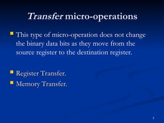
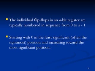
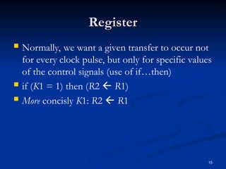
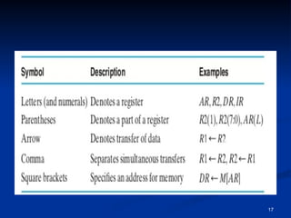
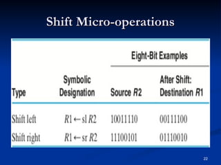
1
Subject : EE227-Digital Logic Design
Lecture
ecture : #24
: #24
Date : 22 April, 2020 Wednesday
Instructor : Mr. Muhammad Kamran
office : Exam Hall (M-117)
Email : muhammad.kamran@nu.edu.pk
In the Name of Allah the Most
Beneficent the Most Merciful
2
Outline
 Micro-operations
 Transfer Micro-operations
 Register Transfer
 Arithmetic Micro-operations.
 Logic Micro-operations.
 Shift Micro-operations.
Micro-operations
Micro-operations
 A micro-operation is an elementary operation
performed on data stored in registers or in
memory.
3
Types of Micro-operations
 Most often encountered micro operations are of
Most often encountered micro operations are of
following four types:
 Transfer micro-operations: which transfer
binary data from one register to another.
 Arithmetic micro-operations: which perform
arithmetic operations on data in registers.
4
5
 Logic micro-operations: which perform bit
manipulation on data in registers.
 Shift micro-operations: which shift data in
registers.
6
 A given micro-operation may be of more than
one type.
 For example: a 1s complement operation is both
an arithmetic micro-operation and a logic micro-
operation.
 All the bits can be inverted -- logic operation
All the bits can be inverted -- logic operation
 11111111 can be added in given 8 bit number
11111111 can be added in given 8 bit number –
–
arithmetic operation.
Transfer micro-operations
 This type of micro-operation does not change
the binary data bits as they move from the
source register to the destination register.
 Register Transfer.
Register Transfer.
 Memory Transfer.
Memory Transfer.
7
Register Transfer:
8
 The movement of the data stored in registers
and the processing performed on the data are
referred to as register transfer operations
 Example:
 Loading the contents of one register into another,
adding the contents of two registers, and
incrementing the con- tents of a register.
9
 The result of the micro-operation may replace
the previous binary data in the register
 Alternatively, the result may be transferred to
another register, leaving the previous data
unchanged
Register Transfer Language
 Register transfer language (RTL): is used to
represent registers and specify the operations on
their contents
 RTL is used to write register transfer micro-
RTL is used to write register transfer micro-
operations.
operations.
10
RTL Rules
RTL Rules
 We denote the registers by uppercase letters
(sometimes followed by numerals) that indicate the
function of the register.
 For example:
 A register that holds an address for the memory unit is
usually called an address register and can be designated by
the name AR
 PC for program counter,
 IR for instruction register,
 R2 for register 2
11
 The individual flip-flops in an n-bit register are
typically numbered in sequence from 0 to n - 1
 Starting with 0 in the least significant (often the
rightmost) position and increasing toward the
most significant position.
12
13
 A register can be partitioned into 2 halves and
A register can be partitioned into 2 halves and
designated with their respective bit sequence in a
parenthesis.
parenthesis.
 Example:
Example:
 PC(7:0), refers to the low-order byte of the register,
and PC(H) or PC(15:8) refers to the high-order byte.
 Data transfer from one register to another is
designated in symbolic form by means of the
replacement operator ().
 R1  R2
 The register R1 is referred to as the source of the
transfer and the register R2 as the destination.
 The contents of the source register do not
change as a result of the transfer.
14
Register
Register
 Normally, we want a given transfer to occur not
for every clock pulse, but only for specific values
of the control signals (use of if…then)
 if (K1 = 1) then (R2  R1)
 More concisly K1: R2  R1
15
16
17
 A comma is used to separate two or more
register transfers that are executed at the same
time
 K3:R2  R1,R1  R2
 Exchanges the contents of two registers
simultaneously for a positive clock edge at which
K3 = 1
18
 The clock is not included as a variable in the
register-transfer statements. It is assumed that all
transfers occur in response to a clock transition.
 Even though the control condition K1 becomes
active at time t, the actual transfer does not
occur until the register is triggered by the next
positive transition of the clock, at time t + 1.
19
Arithmetic Micro-operations
20
Logic Micro-operations
21
Shift Micro-operations
22

DLD_Lecture_24_explained by presentationb.ppt

  • 1.
    1 Subject : EE227-DigitalLogic Design Subject : EE227-Digital Logic Design Lecture ecture : #24 : #24 Date : 22 April, 2020 Wednesday Date : 22 April, 2020 Wednesday Instructor : Mr. Muhammad Kamran Instructor : Mr. Muhammad Kamran office : Exam Hall (M-117) office : Exam Hall (M-117) Email : muhammad.kamran@nu.edu.pk Email : muhammad.kamran@nu.edu.pk In the Name of Allah the Most Beneficent the Most Merciful
  • 2.
    2 Outline  Micro-operations  TransferMicro-operations  Register Transfer  Arithmetic Micro-operations.  Logic Micro-operations.  Shift Micro-operations.
  • 3.
    Micro-operations Micro-operations  A micro-operationis an elementary operation performed on data stored in registers or in memory. 3
  • 4.
    Types of Micro-operations Typesof Micro-operations  Most often encountered micro operations are of Most often encountered micro operations are of following four types: following four types:  Transfer micro-operations: which transfer binary data from one register to another.  Arithmetic micro-operations: which perform arithmetic operations on data in registers. 4
  • 5.
    5  Logic micro-operations:which perform bit manipulation on data in registers.  Shift micro-operations: which shift data in registers.
  • 6.
    6  A givenmicro-operation may be of more than one type.  For example: a 1s complement operation is both an arithmetic micro-operation and a logic micro- operation.  All the bits can be inverted -- logic operation All the bits can be inverted -- logic operation  11111111 can be added in given 8 bit number 11111111 can be added in given 8 bit number – – arithmetic operation. arithmetic operation.
  • 7.
    Transfer micro-operations  Thistype of micro-operation does not change the binary data bits as they move from the source register to the destination register.  Register Transfer. Register Transfer.  Memory Transfer. Memory Transfer. 7
  • 8.
    Register Transfer: 8  Themovement of the data stored in registers and the processing performed on the data are referred to as register transfer operations  Example:  Loading the contents of one register into another, adding the contents of two registers, and incrementing the con- tents of a register.
  • 9.
    9  The resultof the micro-operation may replace the previous binary data in the register  Alternatively, the result may be transferred to another register, leaving the previous data unchanged
  • 10.
    Register Transfer Language RegisterTransfer Language  Register transfer language (RTL): is used to represent registers and specify the operations on their contents  RTL is used to write register transfer micro- RTL is used to write register transfer micro- operations. operations. 10
  • 11.
    RTL Rules RTL Rules We denote the registers by uppercase letters (sometimes followed by numerals) that indicate the function of the register.  For example:  A register that holds an address for the memory unit is usually called an address register and can be designated by the name AR  PC for program counter,  IR for instruction register,  R2 for register 2 11
  • 12.
     The individualflip-flops in an n-bit register are typically numbered in sequence from 0 to n - 1  Starting with 0 in the least significant (often the rightmost) position and increasing toward the most significant position. 12
  • 13.
    13  A registercan be partitioned into 2 halves and A register can be partitioned into 2 halves and designated with their respective bit sequence in a designated with their respective bit sequence in a parenthesis. parenthesis.  Example: Example:  PC(7:0), refers to the low-order byte of the register, and PC(H) or PC(15:8) refers to the high-order byte.
  • 14.
     Data transferfrom one register to another is designated in symbolic form by means of the replacement operator ().  R1  R2  The register R1 is referred to as the source of the transfer and the register R2 as the destination.  The contents of the source register do not change as a result of the transfer. 14
  • 15.
    Register Register  Normally, wewant a given transfer to occur not for every clock pulse, but only for specific values of the control signals (use of if…then)  if (K1 = 1) then (R2  R1)  More concisly K1: R2  R1 15
  • 16.
  • 17.
  • 18.
     A commais used to separate two or more register transfers that are executed at the same time  K3:R2  R1,R1  R2  Exchanges the contents of two registers simultaneously for a positive clock edge at which K3 = 1 18
  • 19.
     The clockis not included as a variable in the register-transfer statements. It is assumed that all transfers occur in response to a clock transition.  Even though the control condition K1 becomes active at time t, the actual transfer does not occur until the register is triggered by the next positive transition of the clock, at time t + 1. 19
  • 20.
  • 21.
  • 22.