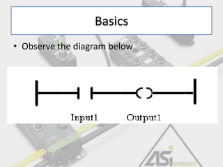
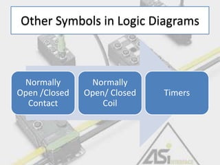
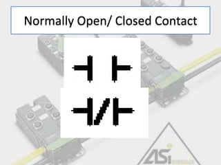
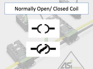
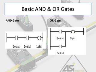
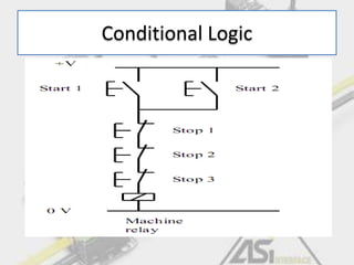
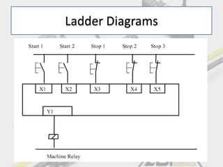
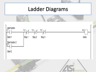
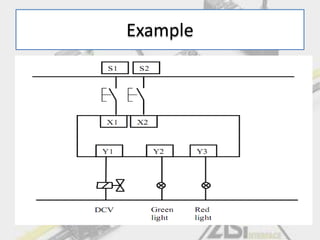
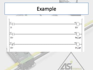
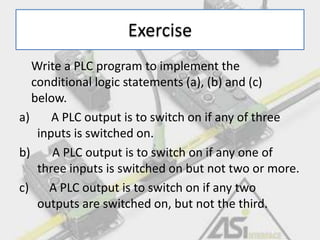
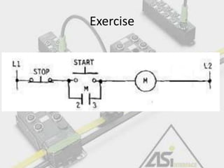
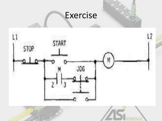
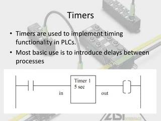
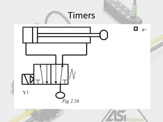
ROLAND NIWAREEBA
CERIANO MBIIKA
EPHRAIM MALINGA
PLC Training Day 2
Ladder
Programming
Basics
• Observe the diagram below
Other Symbols in Logic Diagrams
Normally
Open /Closed
Contact
Normally
Open/ Closed
Coil
Timers
Normally Open/ Closed Contact
Normally Open/ Closed Coil
Basic AND & OR Gates
AND Gate OR Gate
Conditional Logic
Ladder Diagrams
Ladder Diagrams
Outputs and Latches
• These can be used as conditions for other
actions
• For instance, an output can actuate another
sequence of events
Example
Example
Exercise
Write a PLC program to implement the
conditional logic statements (a), (b) and (c)
below.
a) A PLC output is to switch on if any of three
inputs is switched on.
b) A PLC output is to switch on if any one of
three inputs is switched on but not two or more.
c) A PLC output is to switch on if any two
outputs are switched on, but not the third.
Exercise
Exercise
Implementing Latching
• What does the term Latching mean ?
Timers
• Timers are used to implement timing
functionality in PLCs.
• Most basic use is to introduce delays between
processes
Timers
Pulse Generator
Pulse Generator
Pulse Generator
Counters

Programmable Logic Controls training day 2

Editor's Notes

  • #4 The logic of the rung above is such:• If Input1 is ON (or true) - power (logic) completes the circuit from the left rail to the right rail - and Output1 turns ON (or true). • If Input1 is OFF (or false) - then the circuit is not completed and logic does not flow to the right - and Output 1 is OFF (or false).
  • #8 Lets Examine these slides together
  • #9 Various inputs can be organised together to give a set output. This is usually termed as conditional logic. Consider the diagram shown and lets examine the logic behind it
  • #10 Lets connect the circuit to a PLC as shown in the diagram above. Lets consider the implementation of that circuit in a PLC programming interface.
  • #11 Can we build this ladder diagram....Demonstrate the normally closed contact
  • #15 Lets take time to understand these exercises.
  • #20 For example, when a start push button is pressed, the pneumatic cylinder shown in extends, remains extended for 5 seconds and then returns. Draw the PLC wiring diagram and the appropriate ladder logic.
  • #21 Two counters can be combined to make a pulse generator. This is best illustrated by an example.
  • #22 When the Start button in Fig 2.24 is pressed the cylinder in Fig 2.23 oscillates,extending for 2 s and returning for 1 s until the Stop button is pressed.