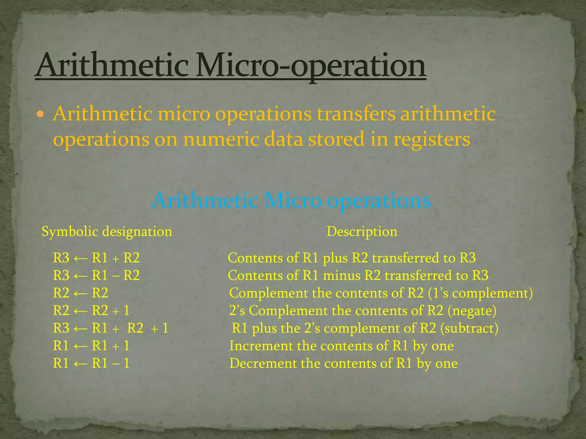
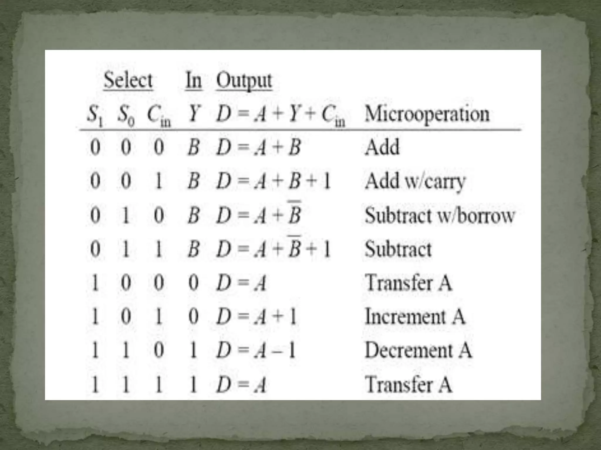
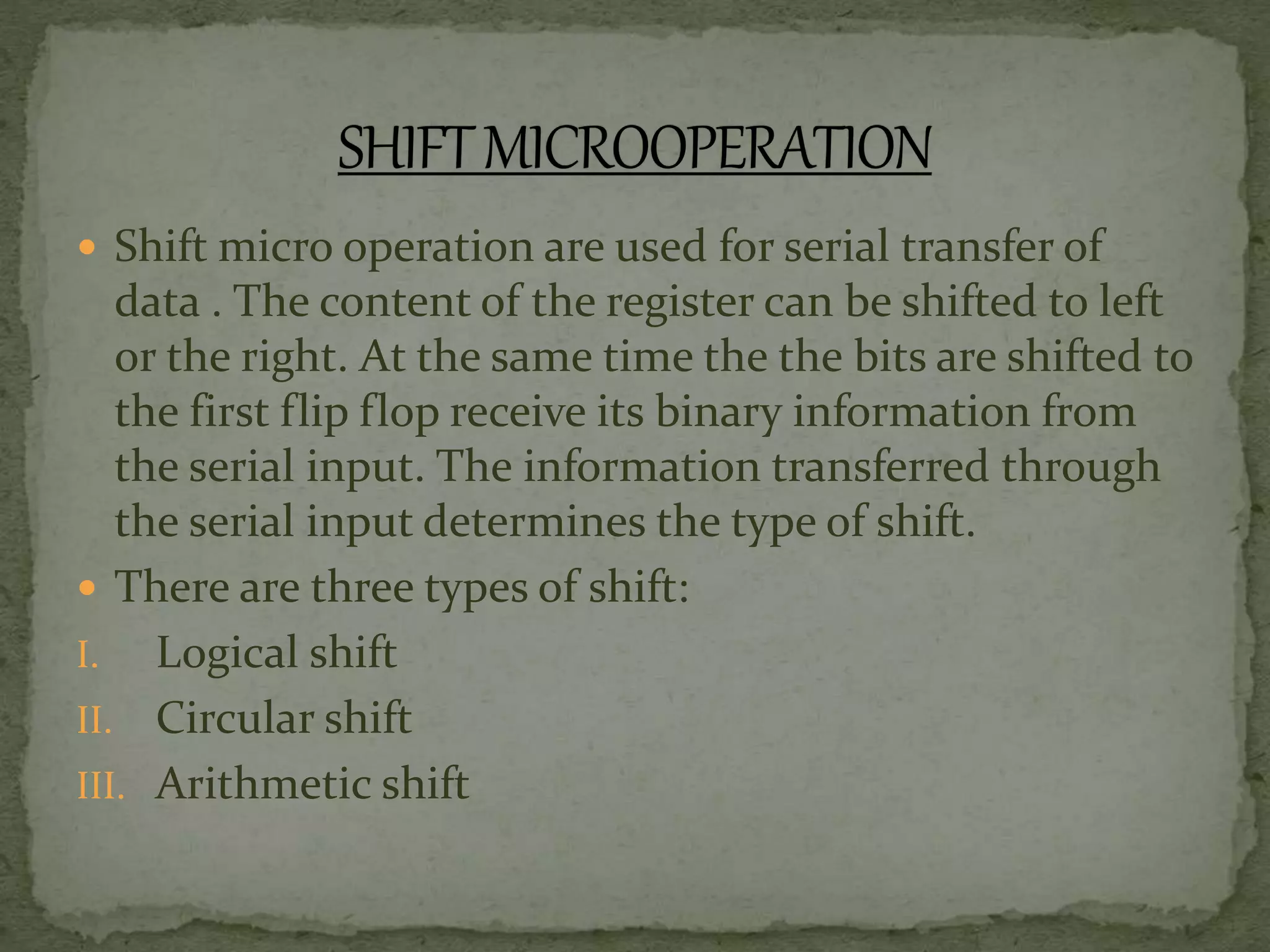
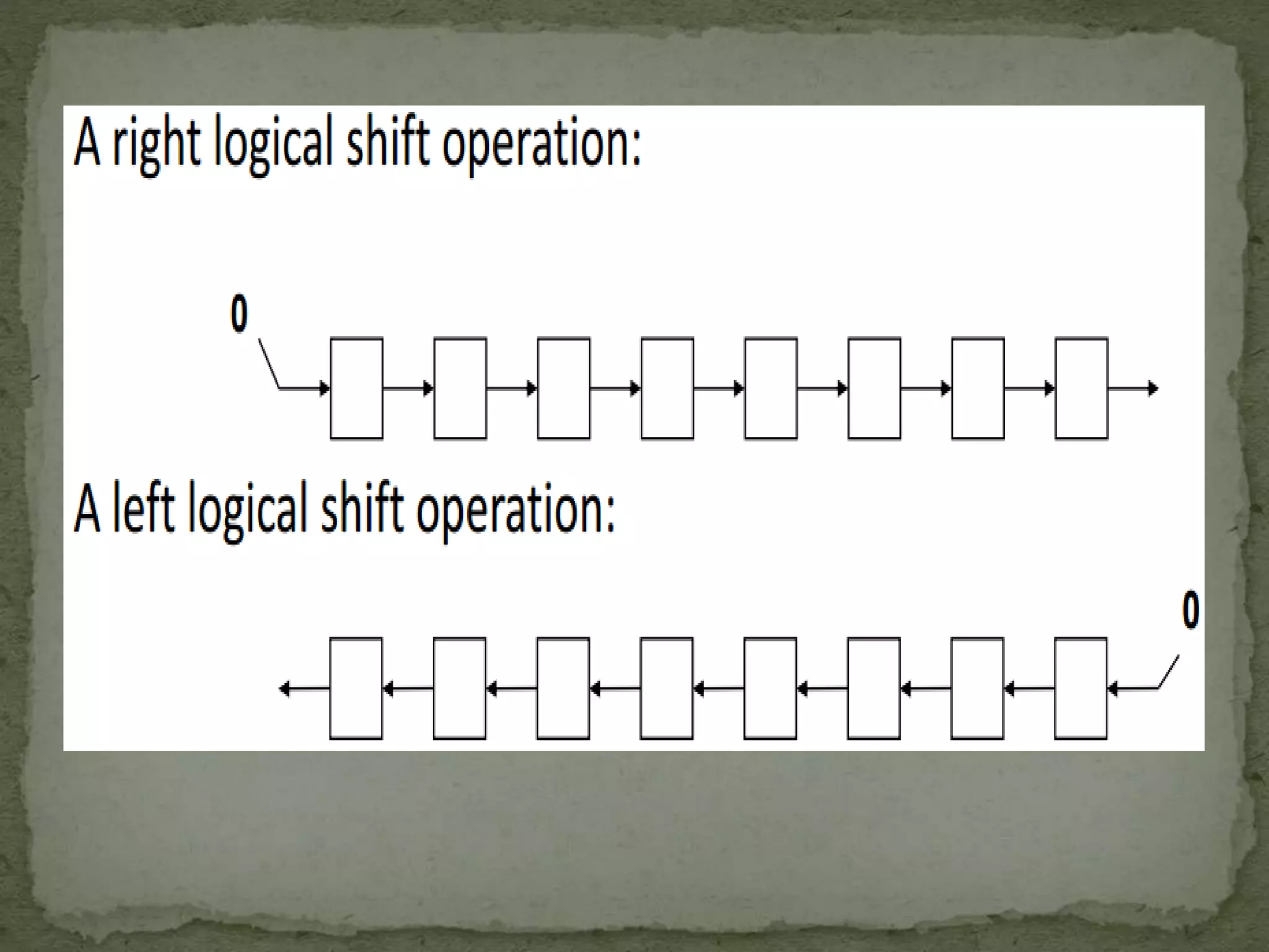
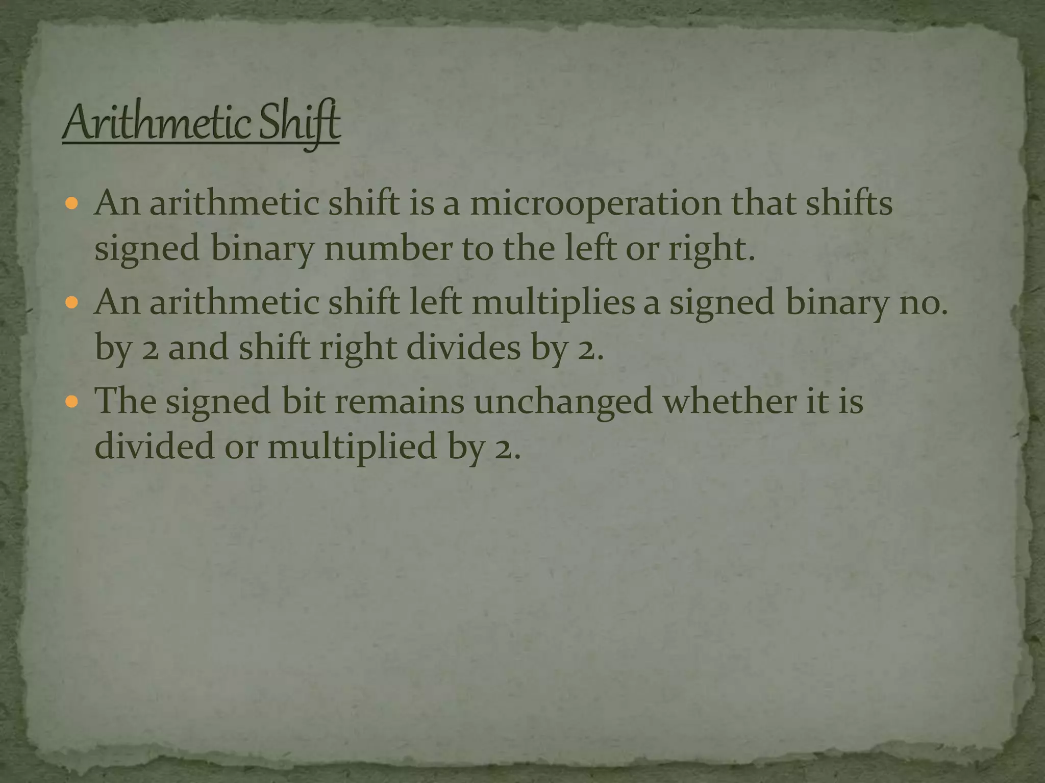
Presented by:
Rakesh R Pillai
 Micro operations are the basic operations that can
be performed by a system on data stored in registers.
Each micro operation describes a
simple operation performed on data in one or more
registers.
 Topics to be understood through this presentation:
 Arithmetic Micro operation
 Logic Micro operation
 Shift Micro operation
 Arithmetic micro operations transfers arithmetic
operations on numeric data stored in registers
Arithmetic Micro operations
Symbolic designation Description
R3 ← R1 + R2 Contents of R1 plus R2 transferred to R3
R3 ← R1 – R2 Contents of R1 minus R2 transferred to R3
R2 ← R2 Complement the contents of R2 (1’s complement)
R2 ← R2 + 1 2’s Complement the contents of R2 (negate)
R3 ← R1 + R2 + 1 R1 plus the 2’s complement of R2 (subtract)
R1 ← R1 + 1 Increment the contents of R1 by one
R1 ← R1 – 1 Decrement the contents of R1 by one
 The digital circuit that generates the arithmetic sum of
two binary numbers of any length is called a Binary
Adder.
 Logic micro operation specify binary operation for
strings of bit stored in registers.
 These operation consider each bit of the register
separately and treat them as binary variables. For
example,
P:R1 R1 R2
1010 Content of R1
1100 Content of R2
0110 Content of R1 after P=1
• SELECTIVE SET:
it sets the bit’s to 1 in register A where there
are 1,s in register B. Example
1010 A before
1100 B(logic operant)
1110 A after
• SELECTIVE COMPLEMENT :
it complements bits in A where there are
corresponding 1’s in B. Example
1010 A before
1100 B
0110 A after
it can be seen selective complement can be done by Exclusive –OR
 SELECTIVE CLEAR:
It clear the bit to 0 in A where there
are corresponding 1’s in B . Example
1010 A before
1100 B
0010 A after
(it can be obtained by micro operation AB’)
 MASKING:
It is similar to selective clear except that the
bit of A is cleared where there corresponding 0’s.
1010 A before
1100 B
1000 A after
 INSERT :
It inserts a new value into a group of bits.
This is done by first masking and then O ring with the
value. Example
0110 1010 A before
0000 1111 B
0000 1010 A after
then insert a new value
0000 1010 A before
1001 0000 B(insert)
1001 1010 A after
 Shift micro operation are used for serial transfer of
data . The content of the register can be shifted to left
or the right. At the same time the the bits are shifted to
the first flip flop receive its binary information from
the serial input. The information transferred through
the serial input determines the type of shift.
 There are three types of shift:
I. Logical shift
II. Circular shift
III. Arithmetic shift
 A logical shift is one that transfer 0 through the serial
input. The bit transferred to the end position through
the serial input is assumed to be zero.
 Example:
R1 shl R1 (1 bit shift to the left)
R2 shr R2(1 bit shift to the right)
 The circular shift(also known as rotate operation)
circulates the bits of the register around the ends
without the loss of information.
 This is accomplished by the connecting the serial
output of the register to the serial input.
 Example:
R1 cil R1(shifts left)
R2 cir R2(shifts right)
 An arithmetic shift is a microoperation that shifts
signed binary number to the left or right.
 An arithmetic shift left multiplies a signed binary no.
by 2 and shift right divides by 2.
 The signed bit remains unchanged whether it is
divided or multiplied by 2.
 The arithmetic shift right leaves the sign bit unchanged
and shift the no.(including the sign bit) to the right the bit
Rn-1 remain unchanged and R0 is lost.
 The arithmetic shift left insert a 0 into R0 and shifts all the
other bits to the left. The initial bit of Rn-1 is lost and
replaced by the bit from Rn-2.A sign reversal occurs if the
bit in Rn-1 changes in the value after shift. This happens if
the multiplication by 2 causes an overflow.
 An over-flow flip-flop Vs can be used to detect an
arithmetic shift left overflow.
Vs=Rn-1 Rn-2
 If Vs=0,there is no overflow, if Vs=1 there is overflow and a
sign reversal takes place. Vs must be transferred into the
over flow with the same clock pulse that shifts the register.
Microoperations
Microoperations
Microoperations
Microoperations

Microoperations

  • 1.
  • 2.
     Micro operationsare the basic operations that can be performed by a system on data stored in registers. Each micro operation describes a simple operation performed on data in one or more registers.  Topics to be understood through this presentation:  Arithmetic Micro operation  Logic Micro operation  Shift Micro operation
  • 3.
     Arithmetic microoperations transfers arithmetic operations on numeric data stored in registers Arithmetic Micro operations Symbolic designation Description R3 ← R1 + R2 Contents of R1 plus R2 transferred to R3 R3 ← R1 – R2 Contents of R1 minus R2 transferred to R3 R2 ← R2 Complement the contents of R2 (1’s complement) R2 ← R2 + 1 2’s Complement the contents of R2 (negate) R3 ← R1 + R2 + 1 R1 plus the 2’s complement of R2 (subtract) R1 ← R1 + 1 Increment the contents of R1 by one R1 ← R1 – 1 Decrement the contents of R1 by one
  • 6.
     The digitalcircuit that generates the arithmetic sum of two binary numbers of any length is called a Binary Adder.
  • 7.
     Logic microoperation specify binary operation for strings of bit stored in registers.  These operation consider each bit of the register separately and treat them as binary variables. For example, P:R1 R1 R2 1010 Content of R1 1100 Content of R2 0110 Content of R1 after P=1
  • 11.
    • SELECTIVE SET: itsets the bit’s to 1 in register A where there are 1,s in register B. Example 1010 A before 1100 B(logic operant) 1110 A after • SELECTIVE COMPLEMENT : it complements bits in A where there are corresponding 1’s in B. Example 1010 A before 1100 B 0110 A after it can be seen selective complement can be done by Exclusive –OR
  • 12.
     SELECTIVE CLEAR: Itclear the bit to 0 in A where there are corresponding 1’s in B . Example 1010 A before 1100 B 0010 A after (it can be obtained by micro operation AB’)  MASKING: It is similar to selective clear except that the bit of A is cleared where there corresponding 0’s. 1010 A before 1100 B 1000 A after
  • 13.
     INSERT : Itinserts a new value into a group of bits. This is done by first masking and then O ring with the value. Example 0110 1010 A before 0000 1111 B 0000 1010 A after then insert a new value 0000 1010 A before 1001 0000 B(insert) 1001 1010 A after
  • 14.
     Shift microoperation are used for serial transfer of data . The content of the register can be shifted to left or the right. At the same time the the bits are shifted to the first flip flop receive its binary information from the serial input. The information transferred through the serial input determines the type of shift.  There are three types of shift: I. Logical shift II. Circular shift III. Arithmetic shift
  • 16.
     A logicalshift is one that transfer 0 through the serial input. The bit transferred to the end position through the serial input is assumed to be zero.  Example: R1 shl R1 (1 bit shift to the left) R2 shr R2(1 bit shift to the right)
  • 18.
     The circularshift(also known as rotate operation) circulates the bits of the register around the ends without the loss of information.  This is accomplished by the connecting the serial output of the register to the serial input.  Example: R1 cil R1(shifts left) R2 cir R2(shifts right)
  • 20.
     An arithmeticshift is a microoperation that shifts signed binary number to the left or right.  An arithmetic shift left multiplies a signed binary no. by 2 and shift right divides by 2.  The signed bit remains unchanged whether it is divided or multiplied by 2.
  • 21.
     The arithmeticshift right leaves the sign bit unchanged and shift the no.(including the sign bit) to the right the bit Rn-1 remain unchanged and R0 is lost.  The arithmetic shift left insert a 0 into R0 and shifts all the other bits to the left. The initial bit of Rn-1 is lost and replaced by the bit from Rn-2.A sign reversal occurs if the bit in Rn-1 changes in the value after shift. This happens if the multiplication by 2 causes an overflow.  An over-flow flip-flop Vs can be used to detect an arithmetic shift left overflow. Vs=Rn-1 Rn-2  If Vs=0,there is no overflow, if Vs=1 there is overflow and a sign reversal takes place. Vs must be transferred into the over flow with the same clock pulse that shifts the register.