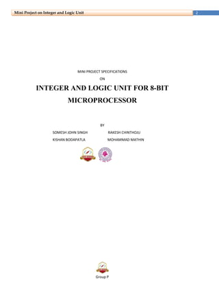
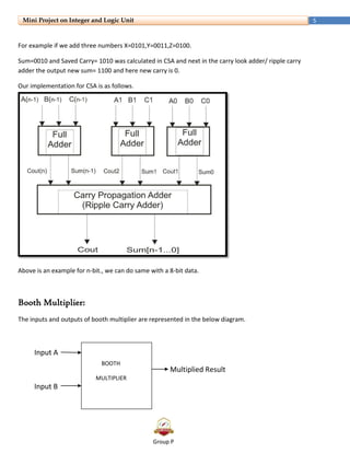
Group-P
Integer and Logic Unit for 8-bit Processor
Group P
2Mini Project on Integer and Logic Unit
MINI PROJECT SPECIFICATIONS
ON
INTEGER AND LOGIC UNIT FOR 8-BIT
MICROPROCESSOR
BY
SOMESH JOHN SINGH RAKESH CHINTHOJU
KISHAN BODAPATLA MOHAMMAD MATHIN
Group P
3Mini Project on Integer and Logic Unit
Integer and Logic Unit:
It is for arithmetic and logic operations. In terms of arithmetic operations, we will focus on adder and
multiplier. And OR & AND operations for Logical terms. The input of the ILU will come from the Memory
Unit. And the operation decision to do a multiplication, add, OR or AND will be decided by the Control
unit. With the address of the instruction, our ILU assumes to act on further operation. To give good
performance with respect to speed, we are given by Booth Multiplier and Carry Save Adder.
Bus Concept:
Data Bus
Address Bus
Control Bus
ALU
Group P
4Mini Project on Integer and Logic Unit
What is an ALU?
ALU stands for: Arithmetic Logic Unit. ALU is a digital circuit that performs Arithmetic (Add, Sub . . .) and
Logical (AND, OR, NOT) operations.
John Von Neumann proposed the ALU in 1945 when he was working on EDVAC.
*Signal representation & ILU*
Carry Save Adder:
The basic CSA (carry save adder) is similar to the full adder but the architecture is different.
The operation and the principle of CSA is based on formulae
A + B + C= SUM+2*CARRY
SUM=(A+B+C)mod2 and COUNT=((A+B+C)-SUM)/2)
Group P
5Mini Project on Integer and Logic Unit
For example if we add three numbers X=0101,Y=0011,Z=0100.
Sum=0010 and Saved Carry= 1010 was calculated in CSA and next in the carry look adder/ ripple carry
adder the output new sum= 1100 and here new carry is 0.
Our implementation for CSA is as follows.
Above is an example for n-bit., we can do same with a 8-bit data.
Booth Multiplier:
The inputs and outputs of booth multiplier are represented in the below diagram.
Input A
Multiplied Result
Input B
R
BOOTH
MULTIPLIER
Group P
6Mini Project on Integer and Logic Unit
Implementation of Booth Multiplier is relying upon the Wallace tree.
A simple Wallace tree for 4 bit mult is given below for understanding. In our project we will be using a 8
bit Wallace tree.
Bus Signals:
Bus signals on ILU are…
3’h0 - Do nothing, complete present operation if any and stay idle
3’h1 – Add signal [1 clock cycle] 3’h2 – Multiply signal [4 clock cycles]
3’h3 - Store the data coming from the data bus into temp 1 register (operand 1) [1 CC]
3’h4 - Store the data coming from the data bus into temp 2 register (operand 2) [1CC]
Group P
7Mini Project on Integer and Logic Unit
3’h5 - Read flag register [1CC] (As soon as the control signal in the same clock cycle the flag status is put
on the one bit bus between ILU and CU.)
3’h6 - Put the data of the result on the data bus. [1 cc]
3’h7-Logical OR operation.[1cc]
3’h8-Logical AND operation.[1cc]
*Timing Diagram of ILU*
Note: This timing diagram is only for MUL operation.
Group P
8Mini Project on Integer and Logic Unit
Reference:
 http://www.eecs.tufts.edu/~ryun01/vlsi/verilog_simulation.htm
 http://www.eecs.tufts.edu/~ryun01/vlsi/chip_architecture.htm
*THANK YOU*

Group p

  • 1.
    Group-P Integer and LogicUnit for 8-bit Processor
  • 2.
    Group P 2Mini Projecton Integer and Logic Unit MINI PROJECT SPECIFICATIONS ON INTEGER AND LOGIC UNIT FOR 8-BIT MICROPROCESSOR BY SOMESH JOHN SINGH RAKESH CHINTHOJU KISHAN BODAPATLA MOHAMMAD MATHIN
  • 3.
    Group P 3Mini Projecton Integer and Logic Unit Integer and Logic Unit: It is for arithmetic and logic operations. In terms of arithmetic operations, we will focus on adder and multiplier. And OR & AND operations for Logical terms. The input of the ILU will come from the Memory Unit. And the operation decision to do a multiplication, add, OR or AND will be decided by the Control unit. With the address of the instruction, our ILU assumes to act on further operation. To give good performance with respect to speed, we are given by Booth Multiplier and Carry Save Adder. Bus Concept: Data Bus Address Bus Control Bus ALU
  • 4.
    Group P 4Mini Projecton Integer and Logic Unit What is an ALU? ALU stands for: Arithmetic Logic Unit. ALU is a digital circuit that performs Arithmetic (Add, Sub . . .) and Logical (AND, OR, NOT) operations. John Von Neumann proposed the ALU in 1945 when he was working on EDVAC. *Signal representation & ILU* Carry Save Adder: The basic CSA (carry save adder) is similar to the full adder but the architecture is different. The operation and the principle of CSA is based on formulae A + B + C= SUM+2*CARRY SUM=(A+B+C)mod2 and COUNT=((A+B+C)-SUM)/2)
  • 5.
    Group P 5Mini Projecton Integer and Logic Unit For example if we add three numbers X=0101,Y=0011,Z=0100. Sum=0010 and Saved Carry= 1010 was calculated in CSA and next in the carry look adder/ ripple carry adder the output new sum= 1100 and here new carry is 0. Our implementation for CSA is as follows. Above is an example for n-bit., we can do same with a 8-bit data. Booth Multiplier: The inputs and outputs of booth multiplier are represented in the below diagram. Input A Multiplied Result Input B R BOOTH MULTIPLIER
  • 6.
    Group P 6Mini Projecton Integer and Logic Unit Implementation of Booth Multiplier is relying upon the Wallace tree. A simple Wallace tree for 4 bit mult is given below for understanding. In our project we will be using a 8 bit Wallace tree. Bus Signals: Bus signals on ILU are… 3’h0 - Do nothing, complete present operation if any and stay idle 3’h1 – Add signal [1 clock cycle] 3’h2 – Multiply signal [4 clock cycles] 3’h3 - Store the data coming from the data bus into temp 1 register (operand 1) [1 CC] 3’h4 - Store the data coming from the data bus into temp 2 register (operand 2) [1CC]
  • 7.
    Group P 7Mini Projecton Integer and Logic Unit 3’h5 - Read flag register [1CC] (As soon as the control signal in the same clock cycle the flag status is put on the one bit bus between ILU and CU.) 3’h6 - Put the data of the result on the data bus. [1 cc] 3’h7-Logical OR operation.[1cc] 3’h8-Logical AND operation.[1cc] *Timing Diagram of ILU* Note: This timing diagram is only for MUL operation.
  • 8.
    Group P 8Mini Projecton Integer and Logic Unit Reference:  http://www.eecs.tufts.edu/~ryun01/vlsi/verilog_simulation.htm  http://www.eecs.tufts.edu/~ryun01/vlsi/chip_architecture.htm *THANK YOU*