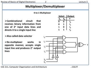
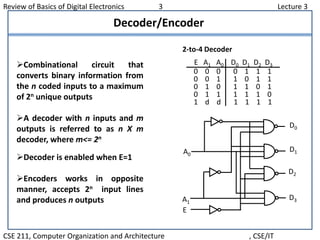
Review of Basics of Digital Electronics 1 Lecture 3
CSE 211, Computer Organization and Architecture , CSE/IT
Overview
Introduction
Logic Gates
Flip Flops
Registers
Counters
Multiplexer/ Demultiplexer
Decoder/ Encoder
Review of Basics of Digital Electronics 2 Lecture 3
CSE 211, Computer Organization and Architecture , CSE/IT
Multiplexer/Demultiplexer
4-to-1 Multiplexer
I0
I1
I2
I3
S0
S1
Y
0 0 I0
0 1 I1
1 0 I2
1 1 I3
Select Output
S1 S0 Y
Combinational circuit that
receives binary information from
one of 2n input data lines and
directs it to a single input line
Also called data selector
De-multiplexer works in
opposite manner, accepts single
input line and produces 2n output
lines
Review of Basics of Digital Electronics 3 Lecture 3
CSE 211, Computer Organization and Architecture , CSE/IT
Decoder/Encoder
Combinational circuit that
converts binary information from
the n coded inputs to a maximum
of 2n unique outputs
A decoder with n inputs and m
outputs is referred to as n X m
decoder, where m<= 2n
Decoder is enabled when E=1
Encoders works in opposite
manner, accepts 2n input lines
and produces n outputs
0 0 0 0 1 1 1
0 0 1 1 0 1 1
0 1 0 1 1 0 1
0 1 1 1 1 1 0
1 d d 1 1 1 1
E A1 A0 D0 D1 D2 D3
2-to-4 Decoder
A0
A1
E
D0
D1
D2
D3
Review of Basics of Digital Electronics 4 Lecture 3
CSE 211, Computer Organization and Architecture , CSE/IT
Decoder/Encoder
0 0 0 0 0 0 0 1 0 0 0
0 0 0 0 0 0 1 0 0 0 1
0 0 0 0 0 1 0 0 0 1 0
0 0 0 0 1 0 0 0 0 1 1
0 0 0 1 0 0 0 0 1 0 0
0 0 1 0 0 0 0 0 1 0 1
0 1 0 0 0 0 0 0 1 1 0
1 0 0 0 0 0 0 0 1 1 1
D7 D6 D5 D4 D3 D2 D1 D0 A2 A1 A0
Octal to Binary Encoder
D1
D2
D3
D5
D6
D7
D4
A0
A1
A2
A0 = D1 + D3 + D5 + D7
A1 = D2 + D3 + D6 + D7
A2 = D4 + D5 + D6 + D7
Review of Basics of Digital Electronics 5 Lecture 3
CSE 211, Computer Organization and Architecture , CSE/IT
Decoder Expansion

Lecture 3

  • 1.
    Review of Basicsof Digital Electronics 1 Lecture 3 CSE 211, Computer Organization and Architecture , CSE/IT Overview Introduction Logic Gates Flip Flops Registers Counters Multiplexer/ Demultiplexer Decoder/ Encoder
  • 2.
    Review of Basicsof Digital Electronics 2 Lecture 3 CSE 211, Computer Organization and Architecture , CSE/IT Multiplexer/Demultiplexer 4-to-1 Multiplexer I0 I1 I2 I3 S0 S1 Y 0 0 I0 0 1 I1 1 0 I2 1 1 I3 Select Output S1 S0 Y Combinational circuit that receives binary information from one of 2n input data lines and directs it to a single input line Also called data selector De-multiplexer works in opposite manner, accepts single input line and produces 2n output lines
  • 3.
    Review of Basicsof Digital Electronics 3 Lecture 3 CSE 211, Computer Organization and Architecture , CSE/IT Decoder/Encoder Combinational circuit that converts binary information from the n coded inputs to a maximum of 2n unique outputs A decoder with n inputs and m outputs is referred to as n X m decoder, where m<= 2n Decoder is enabled when E=1 Encoders works in opposite manner, accepts 2n input lines and produces n outputs 0 0 0 0 1 1 1 0 0 1 1 0 1 1 0 1 0 1 1 0 1 0 1 1 1 1 1 0 1 d d 1 1 1 1 E A1 A0 D0 D1 D2 D3 2-to-4 Decoder A0 A1 E D0 D1 D2 D3
  • 4.
    Review of Basicsof Digital Electronics 4 Lecture 3 CSE 211, Computer Organization and Architecture , CSE/IT Decoder/Encoder 0 0 0 0 0 0 0 1 0 0 0 0 0 0 0 0 0 1 0 0 0 1 0 0 0 0 0 1 0 0 0 1 0 0 0 0 0 1 0 0 0 0 1 1 0 0 0 1 0 0 0 0 1 0 0 0 0 1 0 0 0 0 0 1 0 1 0 1 0 0 0 0 0 0 1 1 0 1 0 0 0 0 0 0 0 1 1 1 D7 D6 D5 D4 D3 D2 D1 D0 A2 A1 A0 Octal to Binary Encoder D1 D2 D3 D5 D6 D7 D4 A0 A1 A2 A0 = D1 + D3 + D5 + D7 A1 = D2 + D3 + D6 + D7 A2 = D4 + D5 + D6 + D7
  • 5.
    Review of Basicsof Digital Electronics 5 Lecture 3 CSE 211, Computer Organization and Architecture , CSE/IT Decoder Expansion