Download to read offline
![International Research Journal of Engineering and Technology (IRJET) e-ISSN: 2395-0056
Volume: 05 Issue: 11 | Nov 2018 www.irjet.net p-ISSN: 2395-0072
© 2018, IRJET | Impact Factor value: 7.211 | ISO 9001:2008 Certified Journal | Page 1367
2.5. OUTPUT DIGITAL SIGNAL
The output of the ADC has defined states and the number of
states is almost always two bits 0 and 1 which is called
binary.
3. SIMULINK MODEL & WAVEFORM
Figure 2: ADC Simulink Model
Figure 3: Analog Signal
Figure 3: Pulse Generator
Figure 4: Sampling
Figure 5: Quantizing.
Figure 6: Encoding
4. CONCLUSION
The Simulink ADC system has a sample-and-hold block
controlled by a sampling pulse generator, an 4 bit encoder
block.
REFERENCES
[1] L. W. Couch II, Modern Communication Systems:
Principle and Applications.
[2] K. Ogata, Modern Control Engineering. Upper Saddle
River, NJ, USA: Prentice Hall PTR, 4th ed., 2001.
[3] http://www.academia.edu/10301729/Abstract_An_Ana
log_to_Digital_converter_ADC_is_crucial
[4] https://www.elprocus.com/analog-to-digital-adc-
converter/
[5] https://whatis.techtarget.com/definition/analog-to-
digital-conversion-ADC
[6] https://ieeexplore.ieee.org/document/5407732/](https://image.slidesharecdn.com/irjet-v5i11263-181207103848/75/IRJET-Analog-to-Digital-Conversion-Process-by-Matlab-Simulink-2-2048.jpg)

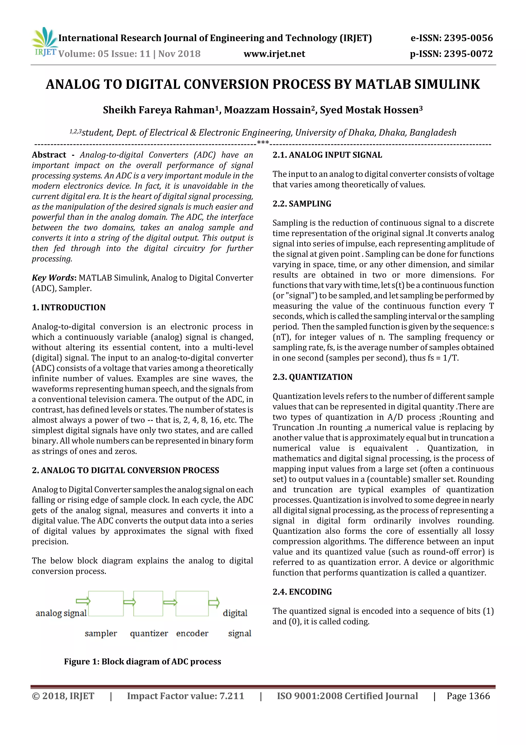
This document describes the process of analog to digital conversion using MATLAB Simulink. It involves sampling an analog input signal, quantizing it to discrete levels, encoding the quantized levels into a binary format, and outputting the digital signal. The key steps are: 1) sampling the analog signal at discrete time intervals, 2) quantizing the sampled signal amplitudes to fixed precision levels, 3) encoding the quantized levels into a binary format of 1s and 0s, which forms the digital output. The document includes block diagrams of the conversion process and figures of the Simulink model used to simulate it.