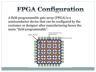
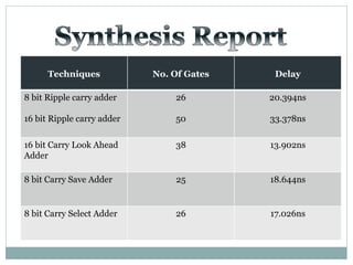
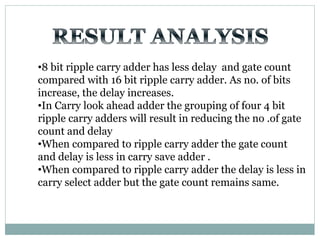
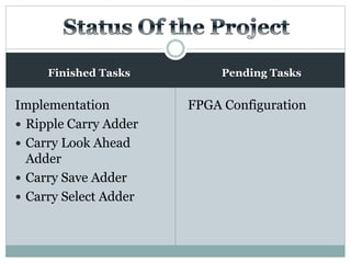
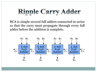
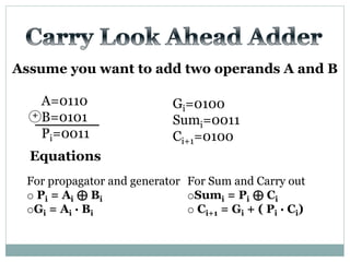
The document discusses different types of adders including ripple carry adder, carry look ahead adder, carry save adder, and carry select adder. It provides details on their working principles, test benches used for verification, gate counts, delays obtained from implementation, and a comparison of their performances. The objectives are to design and implement various adders and analyze their power and delay characteristics. Implementation of the different adders is completed while configuration on FPGA is pending.

![Test Vector
Generator
X
Y
A
B
TEST BENCH DUT
X[7:0]
Y[7:0]
S
Co
S[7:0]
Adders](https://image.slidesharecdn.com/ab1aa7ed-c94a-4d4c-999c-51bc62d1509b-150403005810-conversion-gate01/85/adders-1-10-320.jpg)
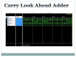
![Test Vector
Generator
X
Y
A
B
TEST BENCH DUT
X[15:0]
Y[15:0]
S
Co
S[15:0]
Carry
Look
Ahead
Adder](https://image.slidesharecdn.com/ab1aa7ed-c94a-4d4c-999c-51bc62d1509b-150403005810-conversion-gate01/85/adders-1-18-320.jpg)
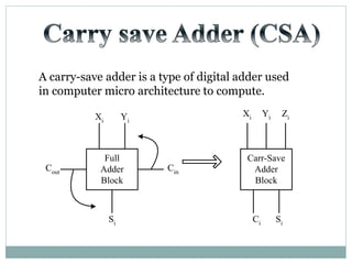
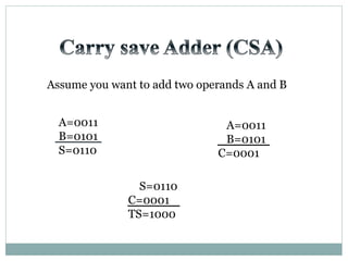
![Test Vector
Generator
X
Y
A
B
TEST BENCH DUT
X[7:0]
Y[7:0]
S
Co
S[7:0]
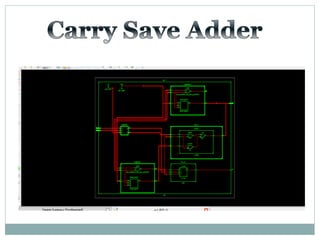
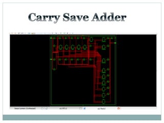
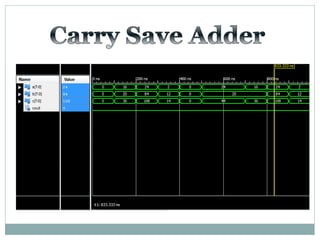
Carry
Save
Adder](https://image.slidesharecdn.com/ab1aa7ed-c94a-4d4c-999c-51bc62d1509b-150403005810-conversion-gate01/85/adders-1-26-320.jpg)
![Test Vector
Generator
X
Y
A
B
TEST BENCH DUT
X[7:0]
Y[7:0]
S
Co
S[7:0]
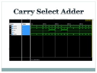
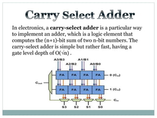
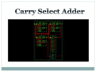
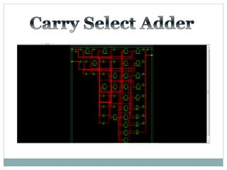
Carry
Select
Adder](https://image.slidesharecdn.com/ab1aa7ed-c94a-4d4c-999c-51bc62d1509b-150403005810-conversion-gate01/85/adders-1-33-320.jpg)