Download as PDF, PPTX

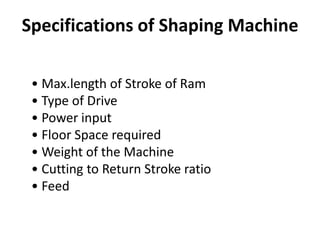


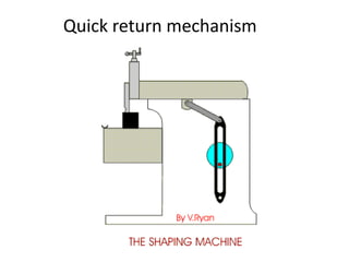
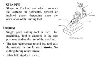

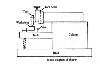
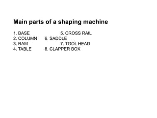


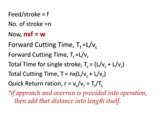
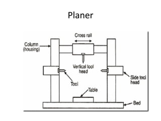

This document provides information about a shaper machine tool. It includes specifications of a shaper such as maximum ram stroke length and power input. It then describes the main parts of a shaper like the base, column, ram, and tool head. Different types of shapers are classified based on ram travel direction, cutting stroke action, and driving mechanism. Common shaping operations like machining horizontal and vertical surfaces are outlined. Formulas for cutting time and quick return ratio are also provided.


