Downloaded 854 times
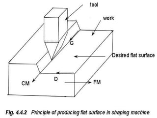
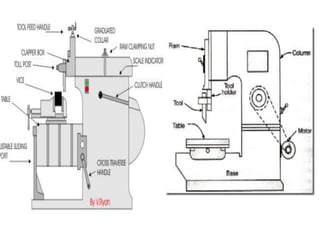
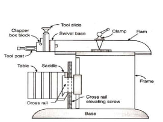
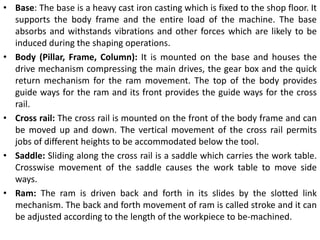
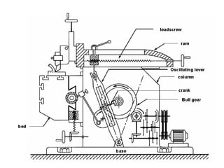
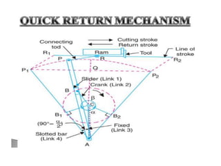
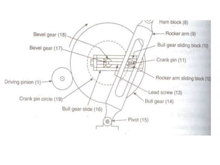
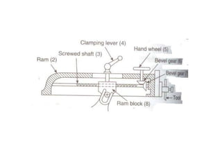

The document describes different types of shaper mechanisms including crank shapers, geared shapers, hydraulic shapers, horizontal shapers, and vertical shapers. It then provides details on the main components of a shaper including the base, body, cross rail, saddle, ram, tool head, and tool post. Finally, it explains different mechanisms used for reciprocating motion of the ram including crank and slotted link mechanisms, Whitworth quick return mechanism, and hydraulic shaper mechanism.


