Download to read offline
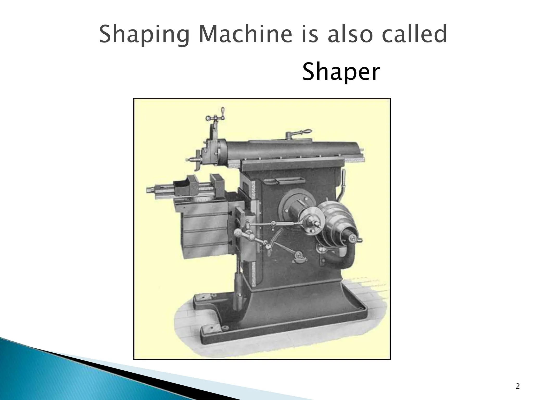
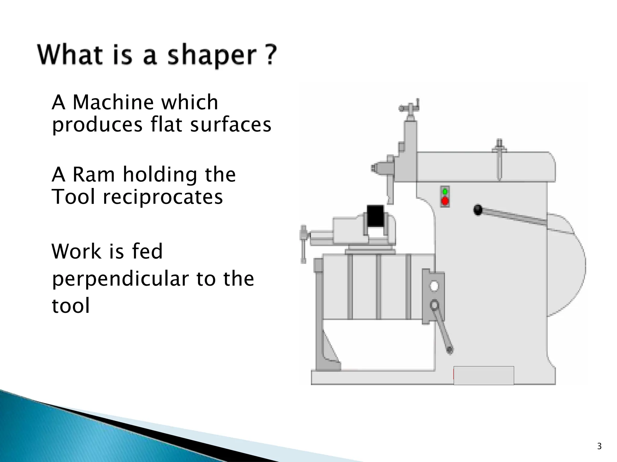
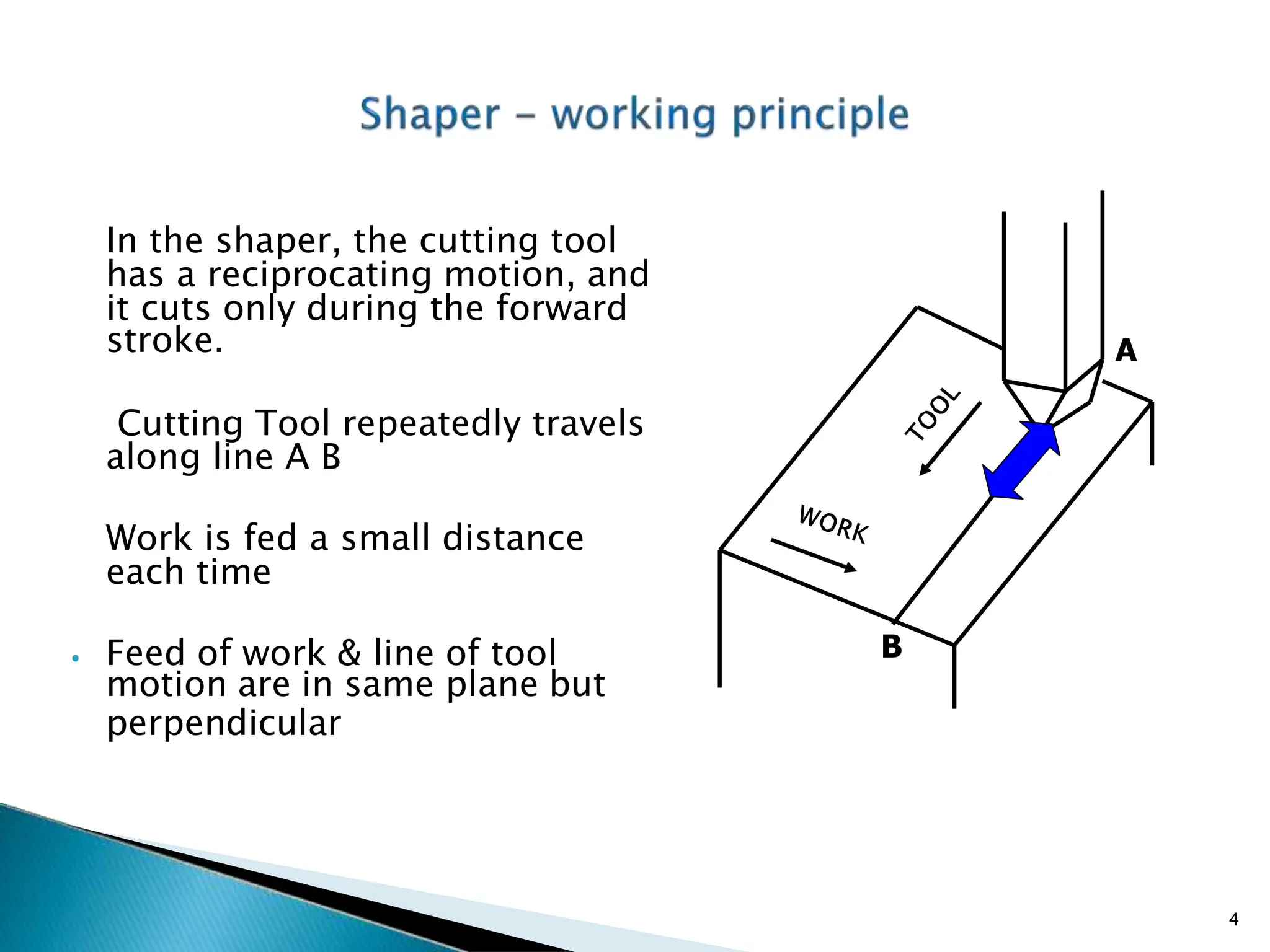
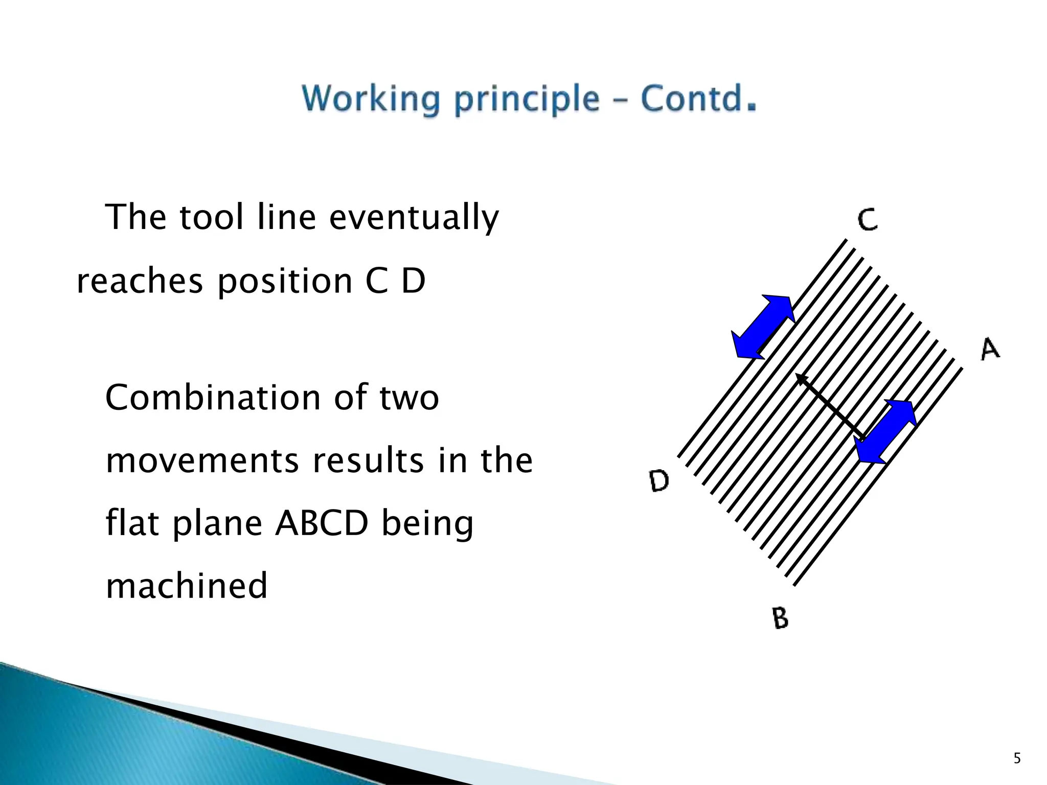
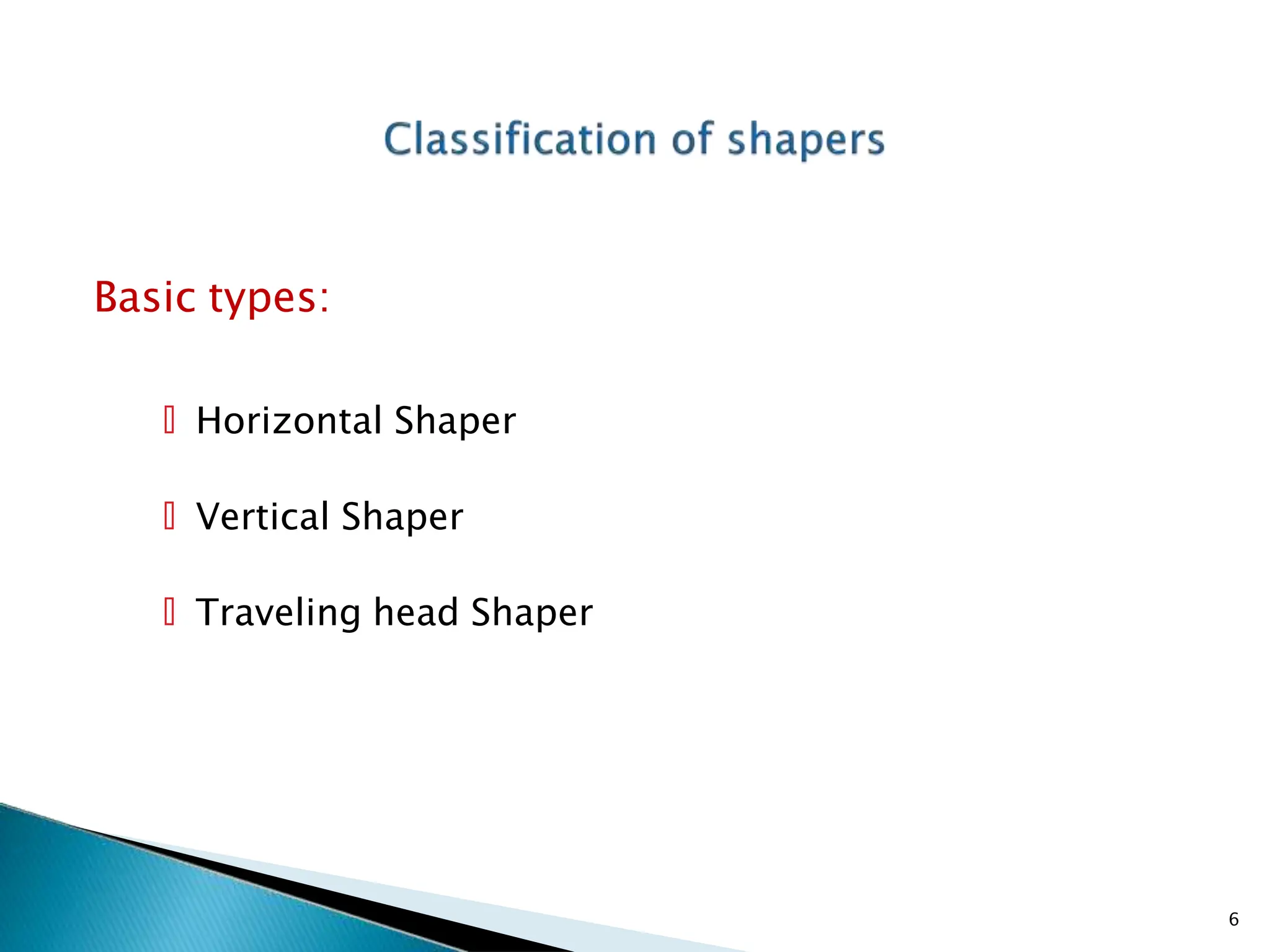
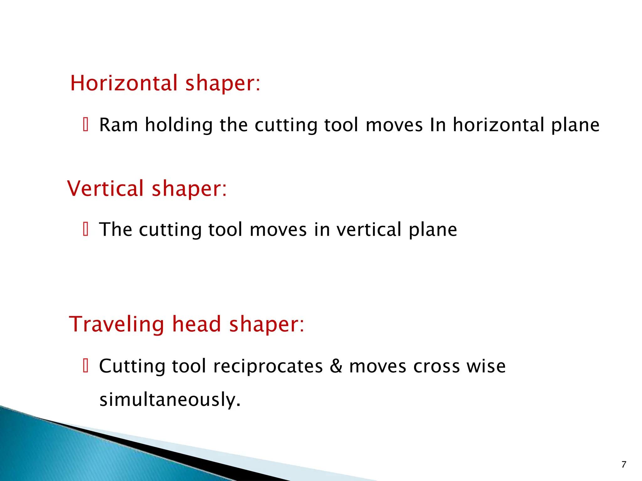
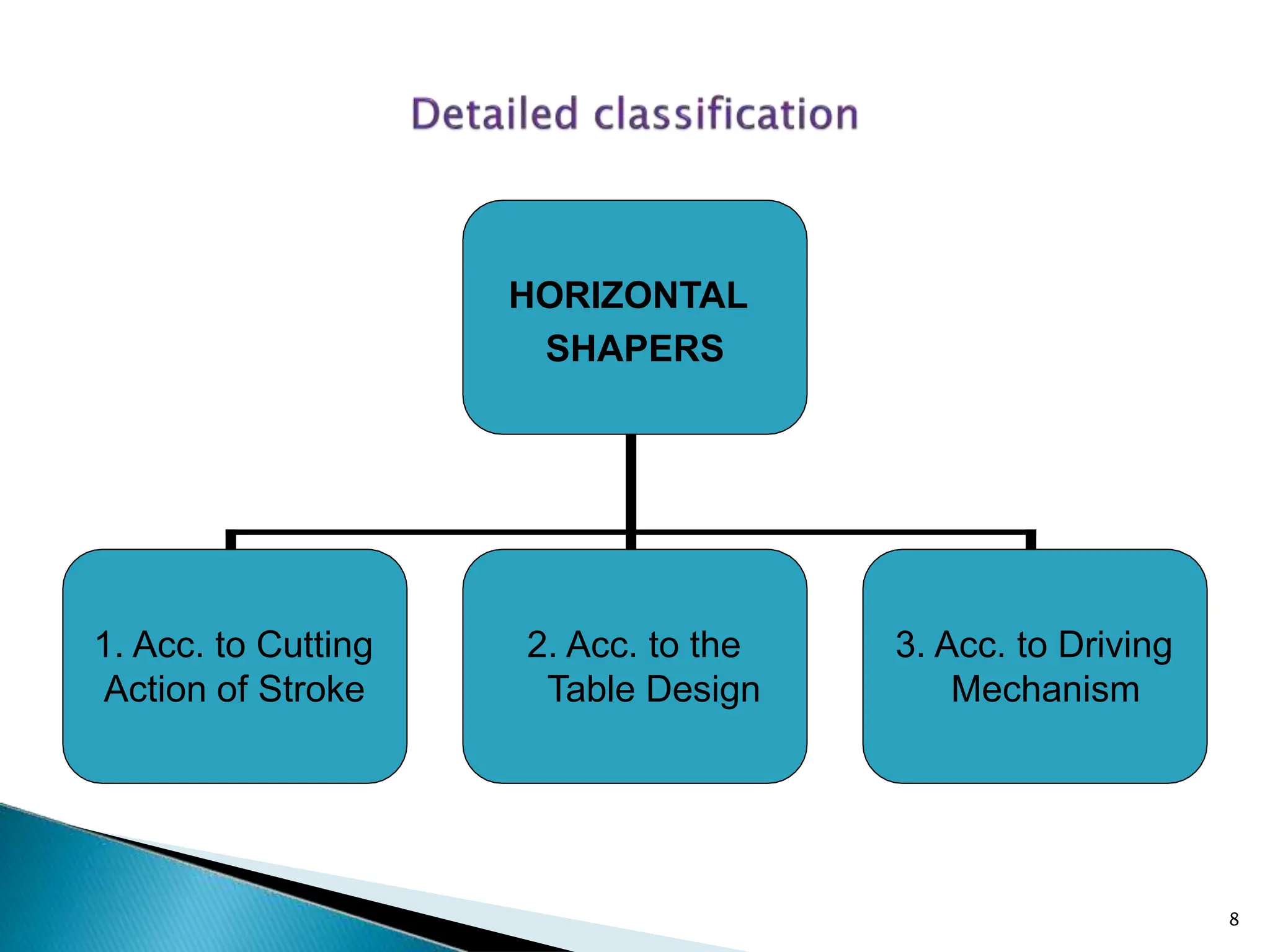
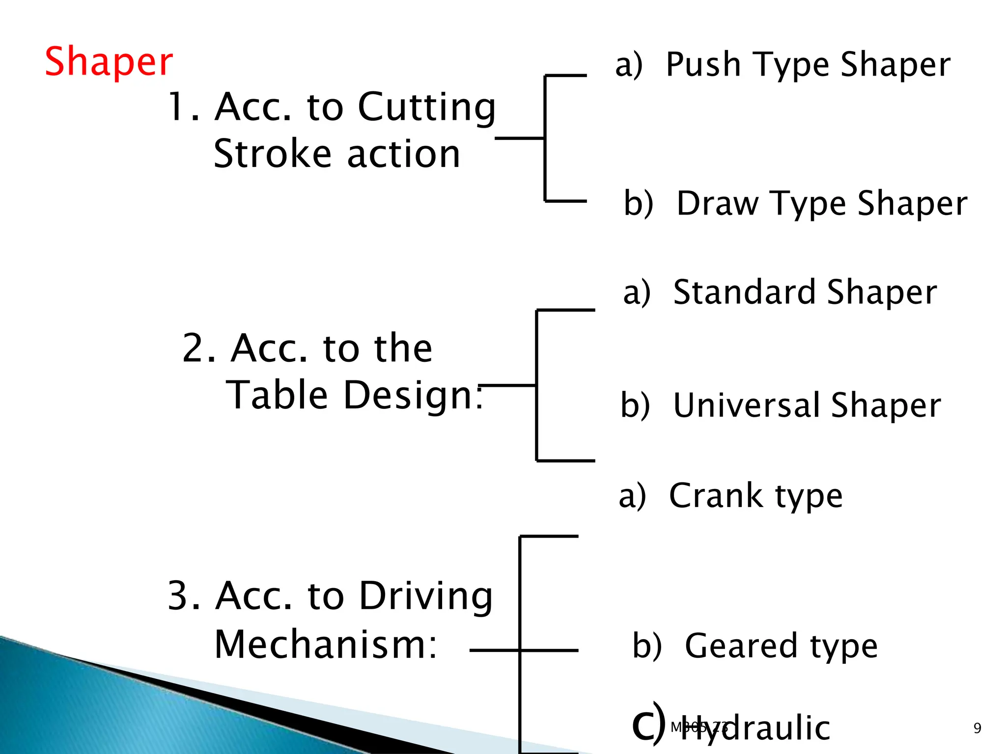
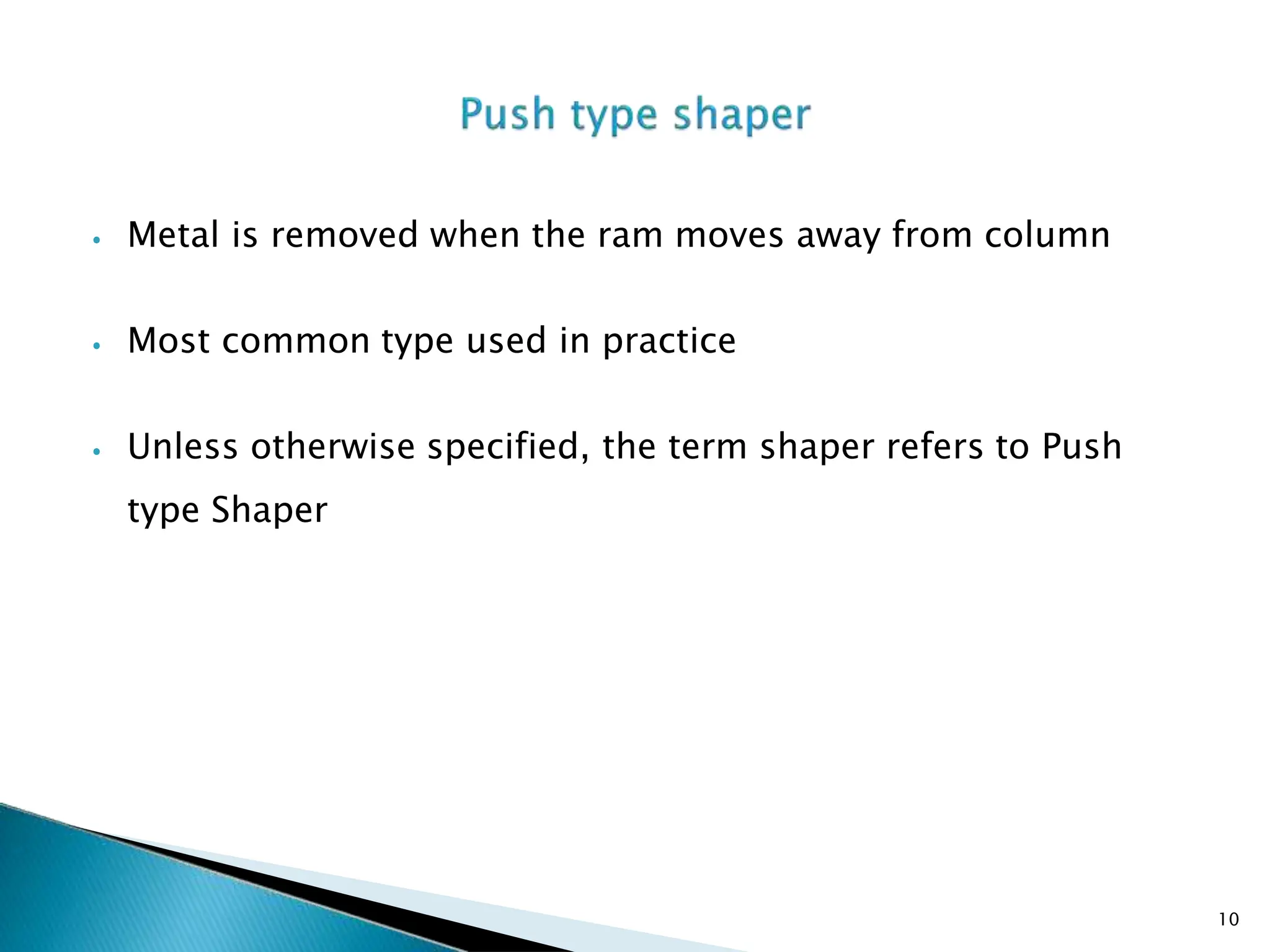
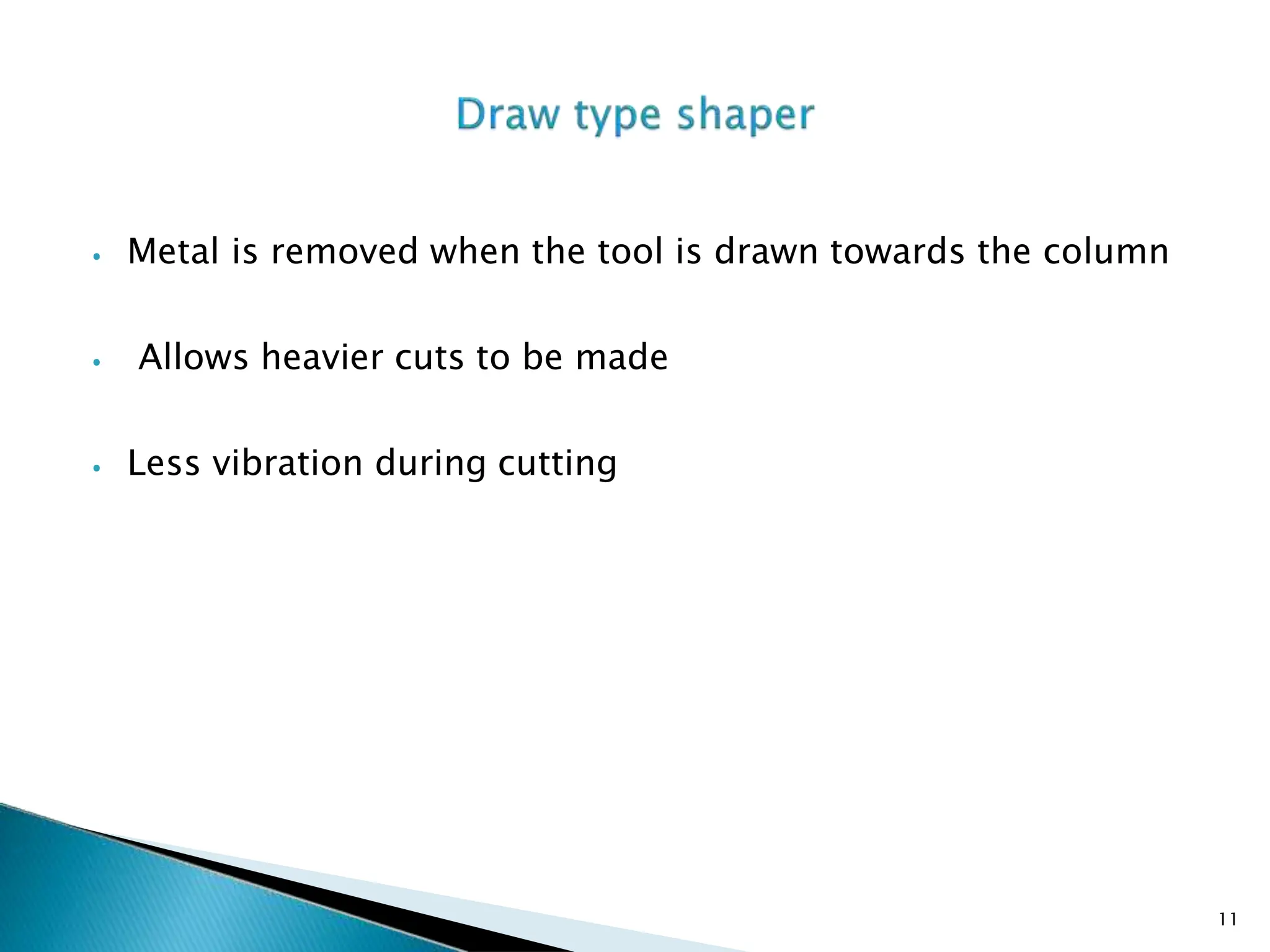
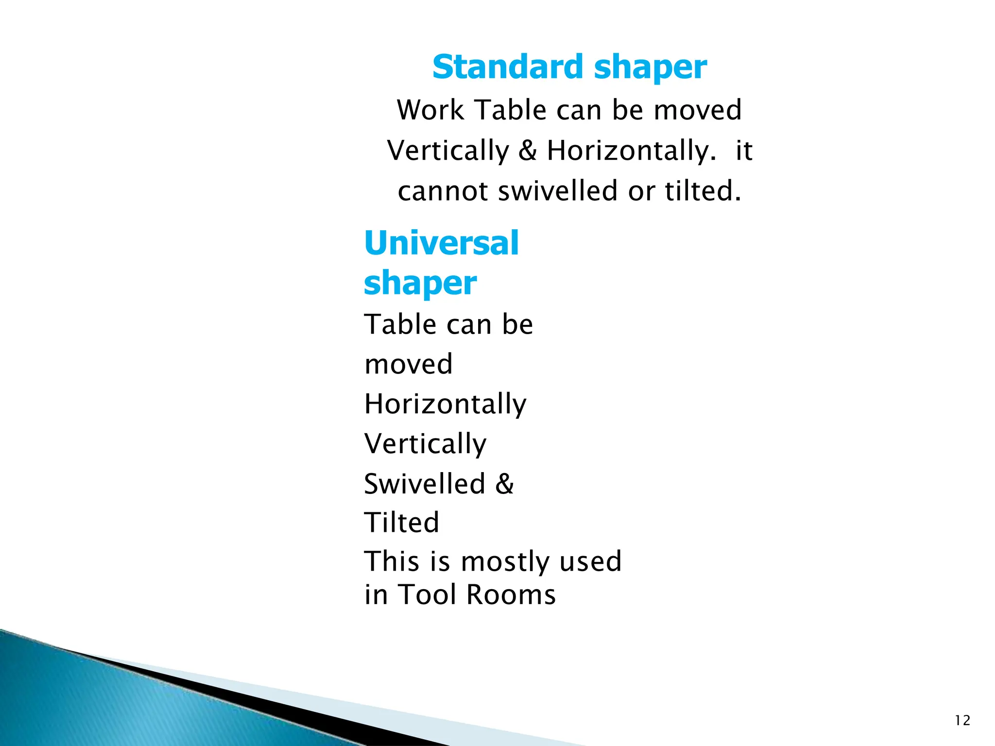
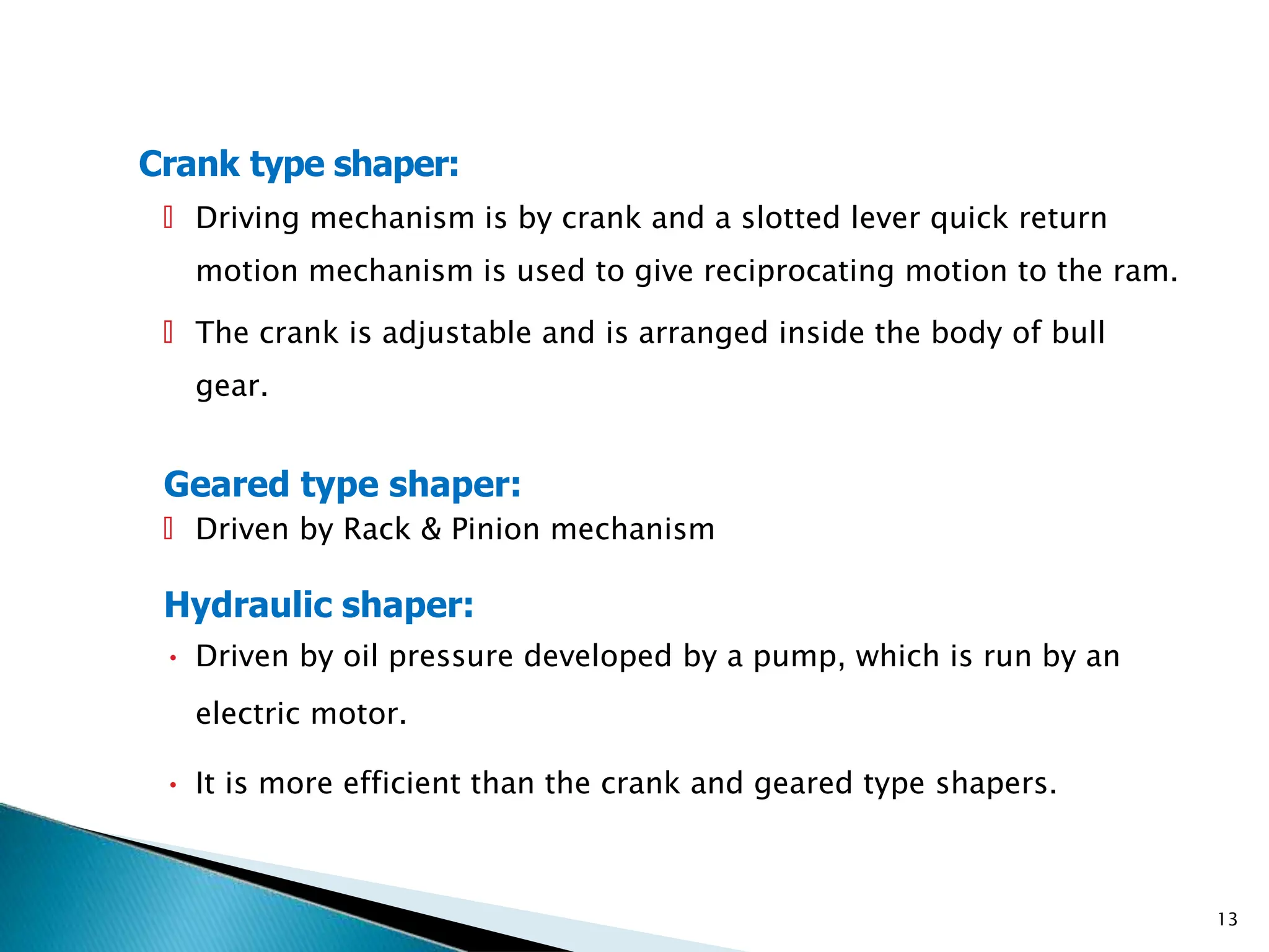
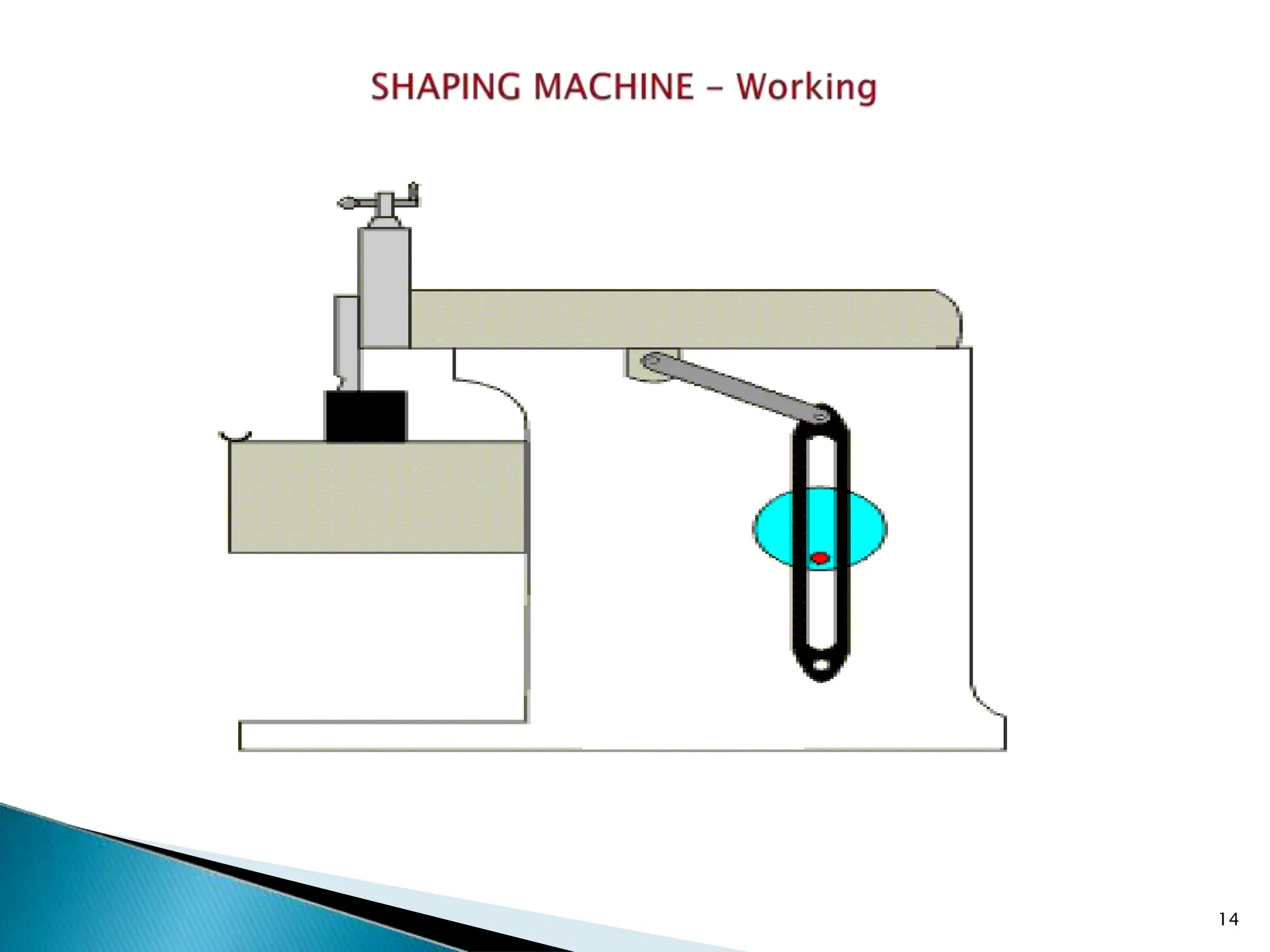
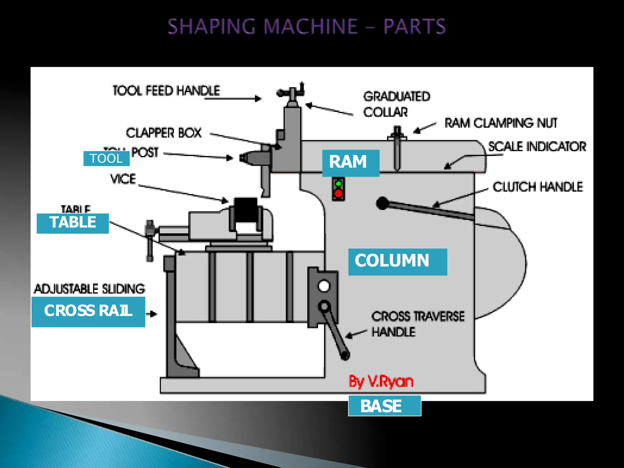
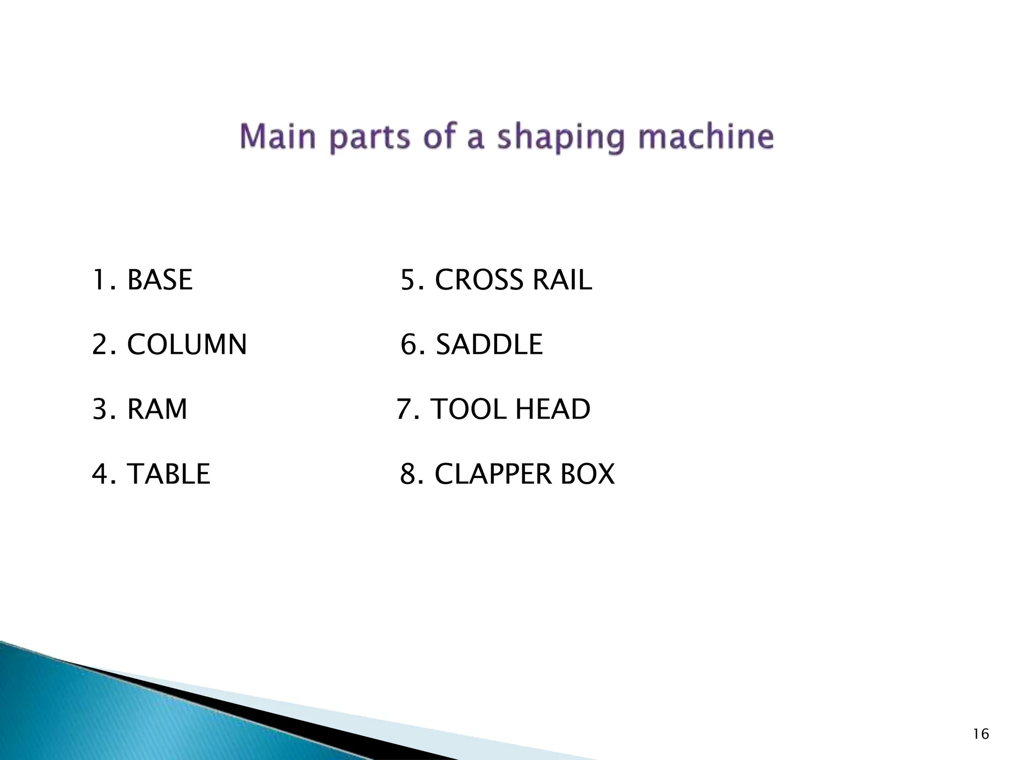
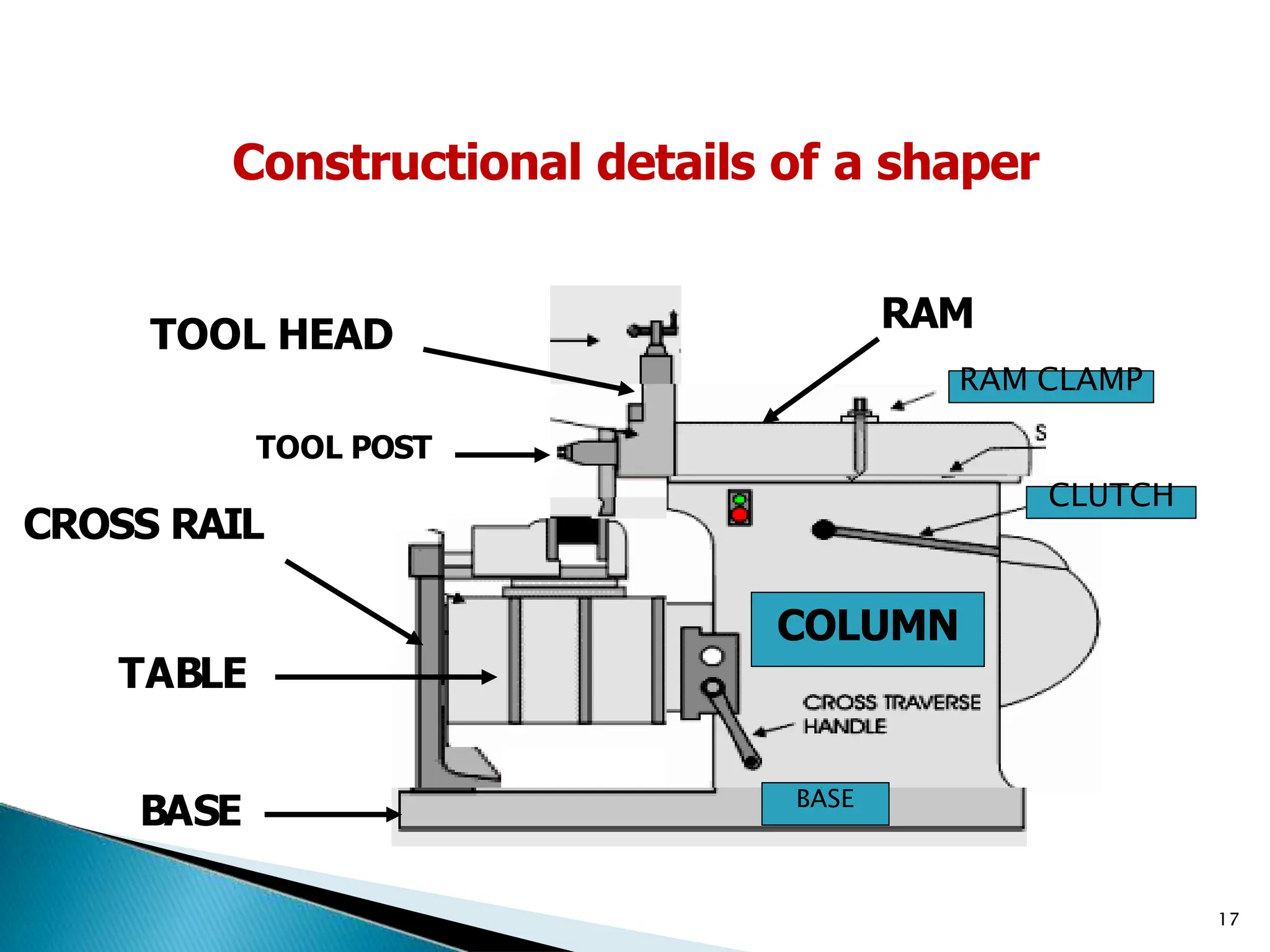
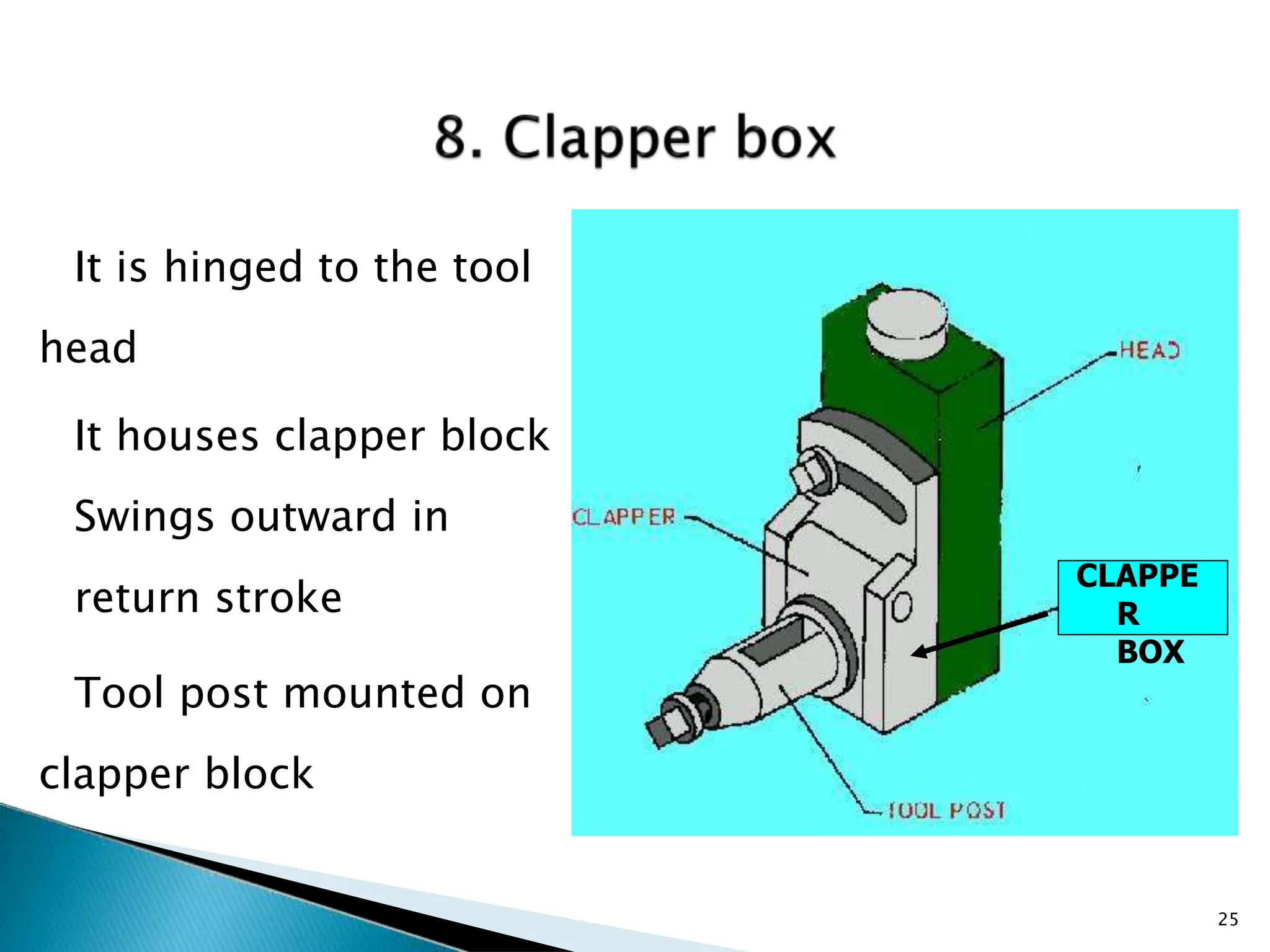


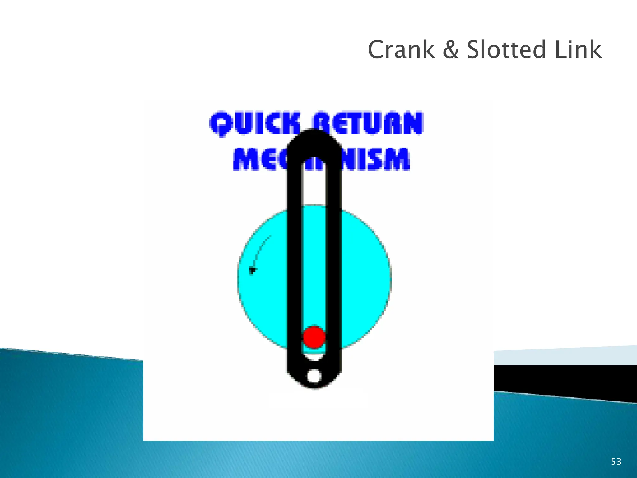
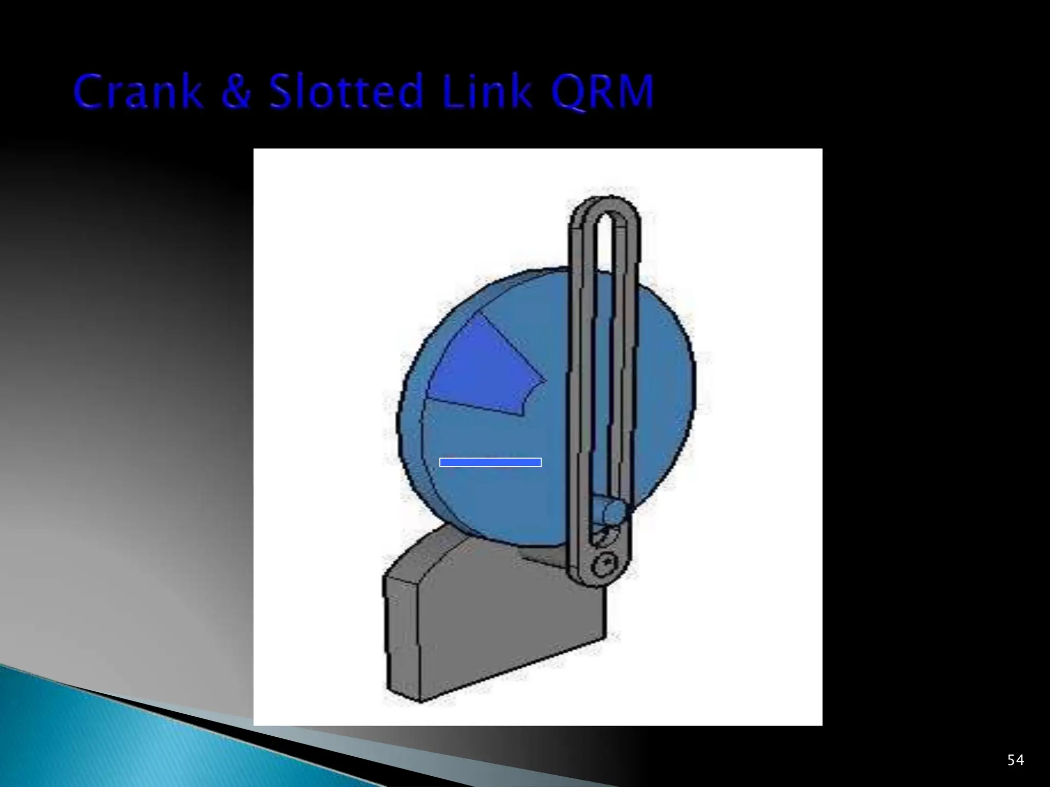
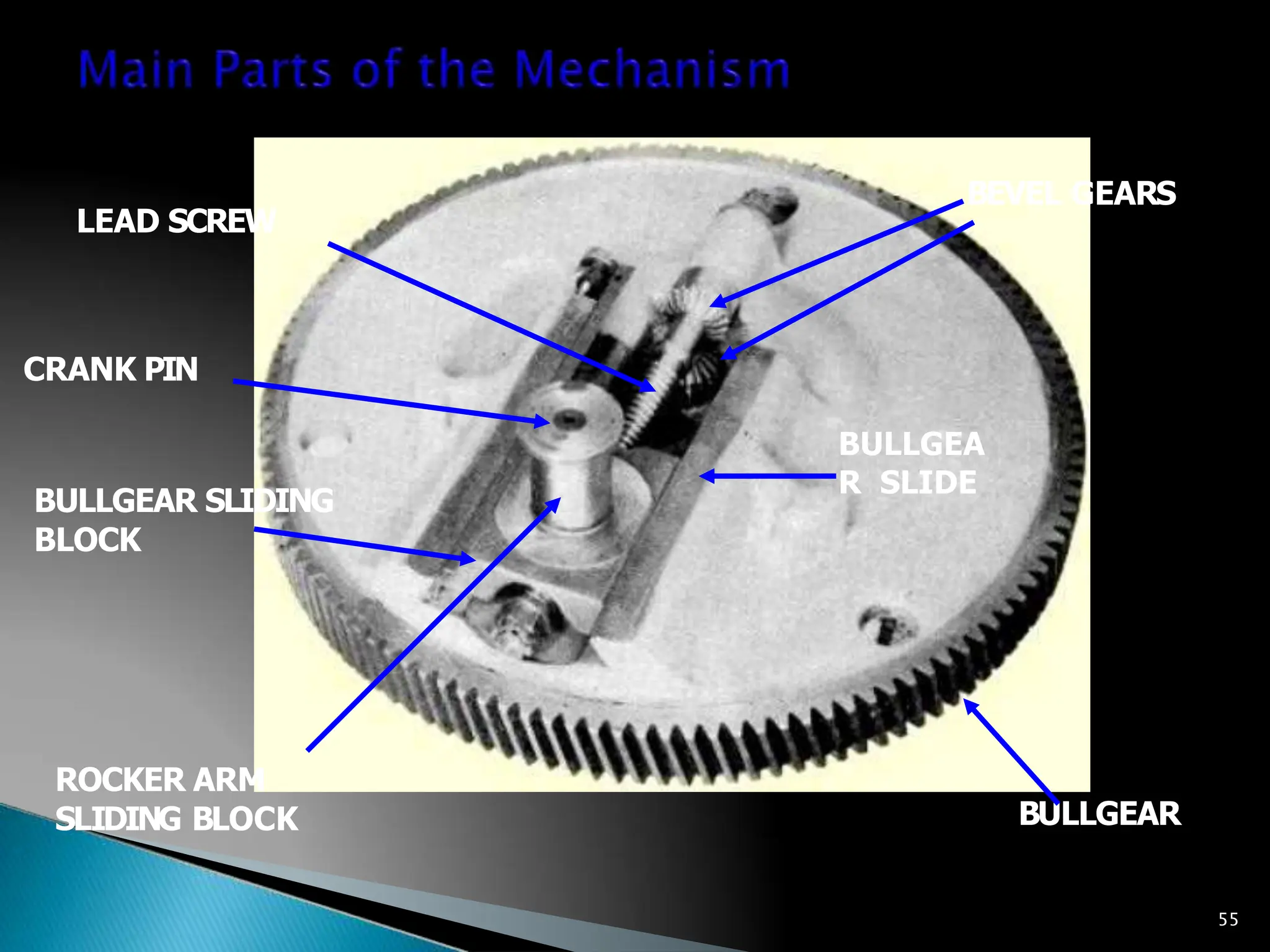
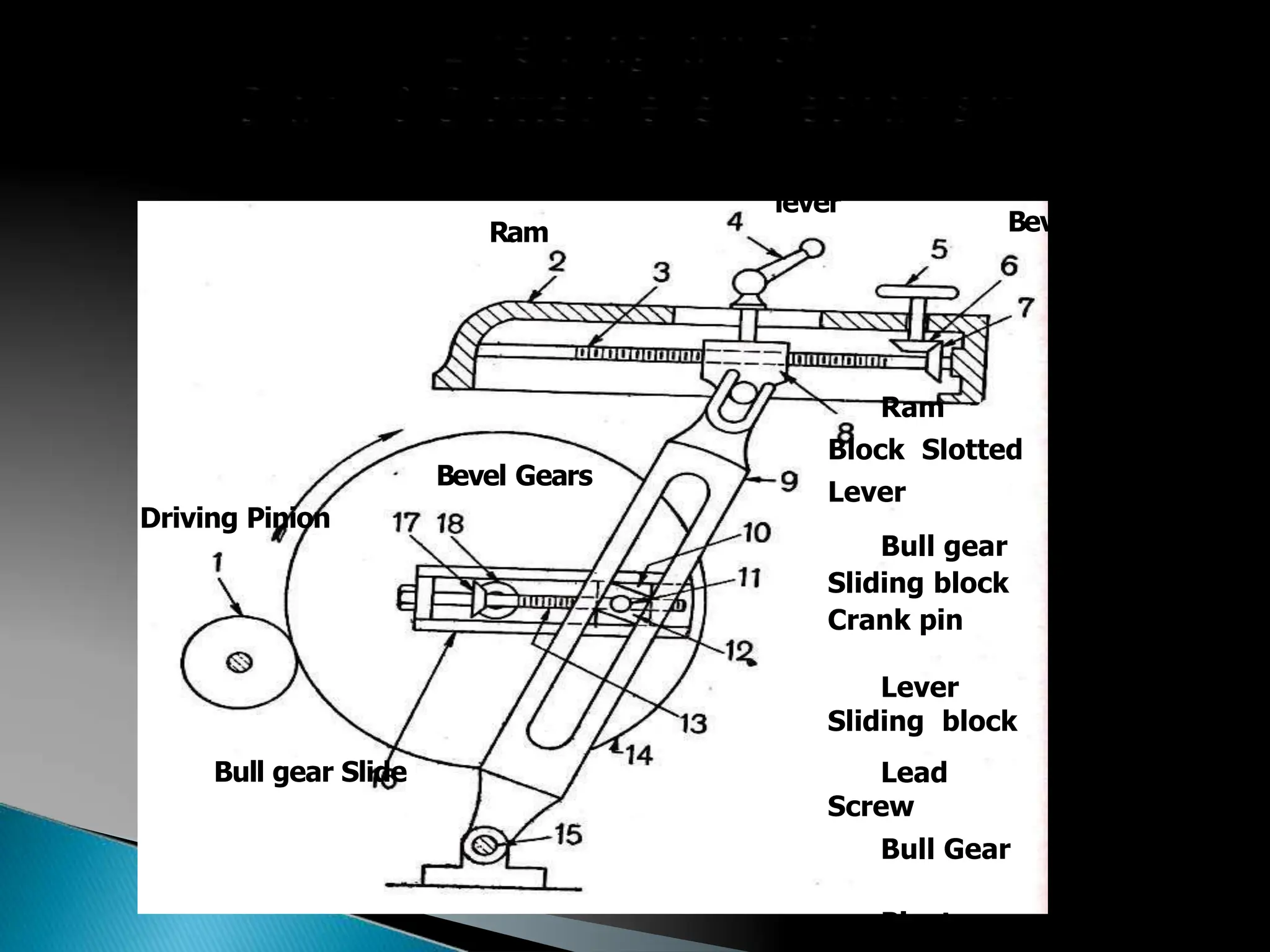
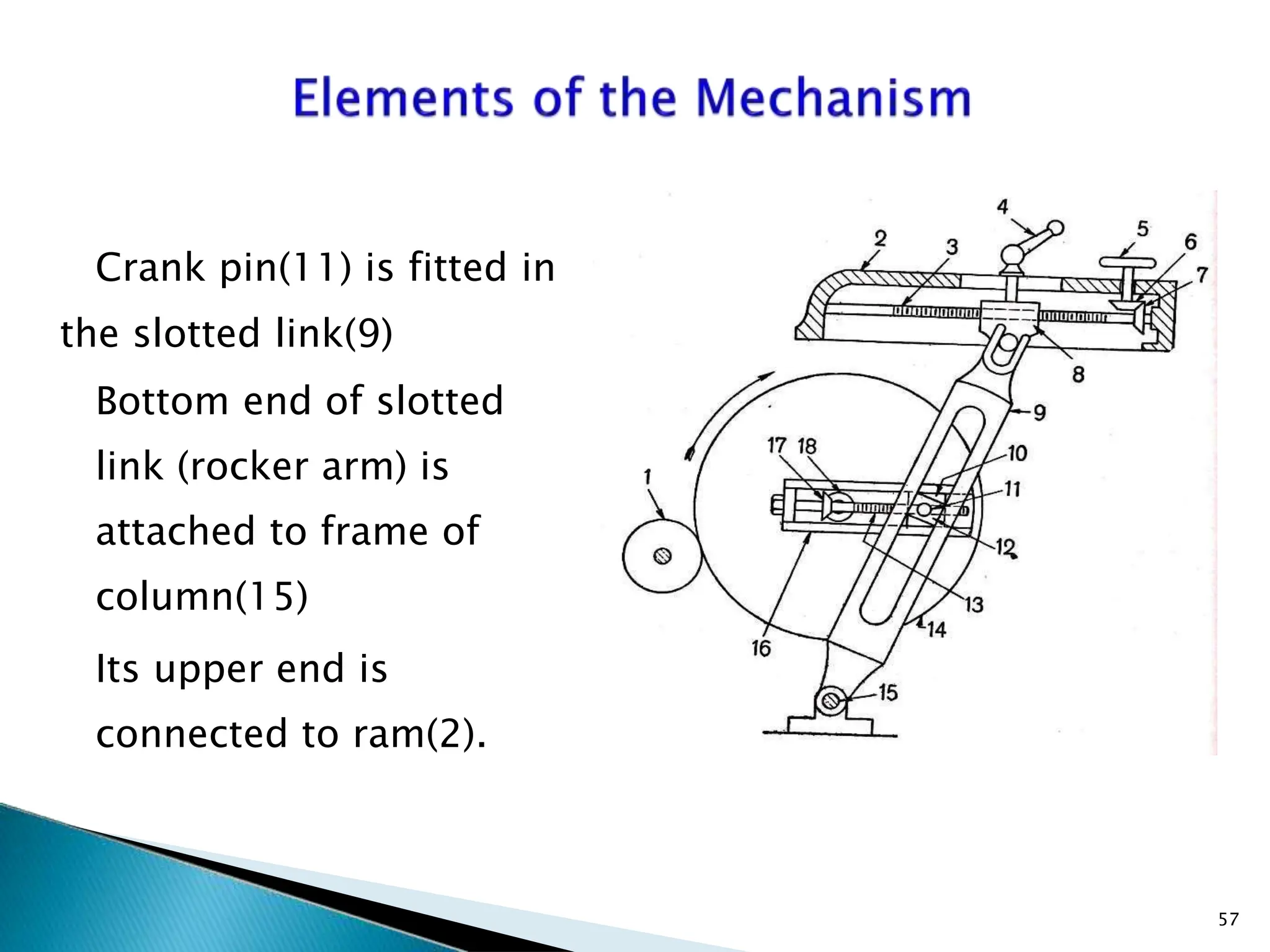

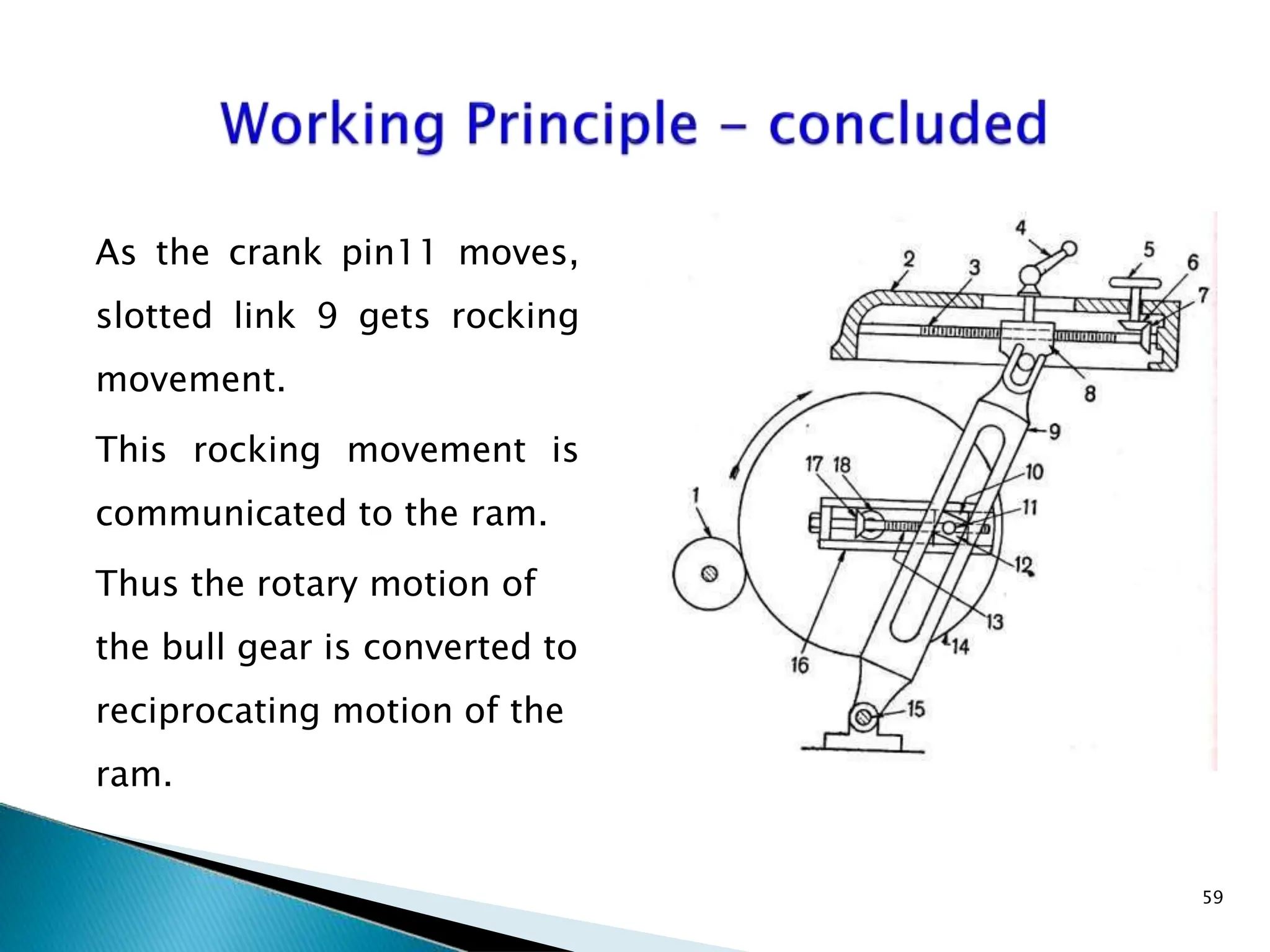


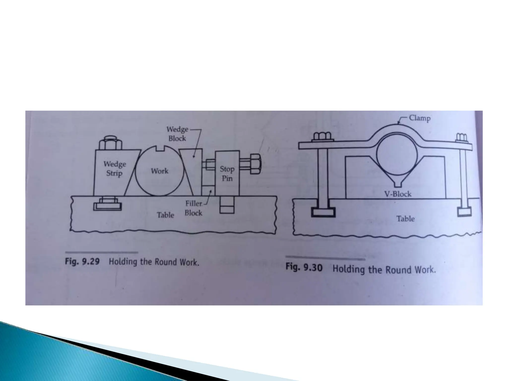
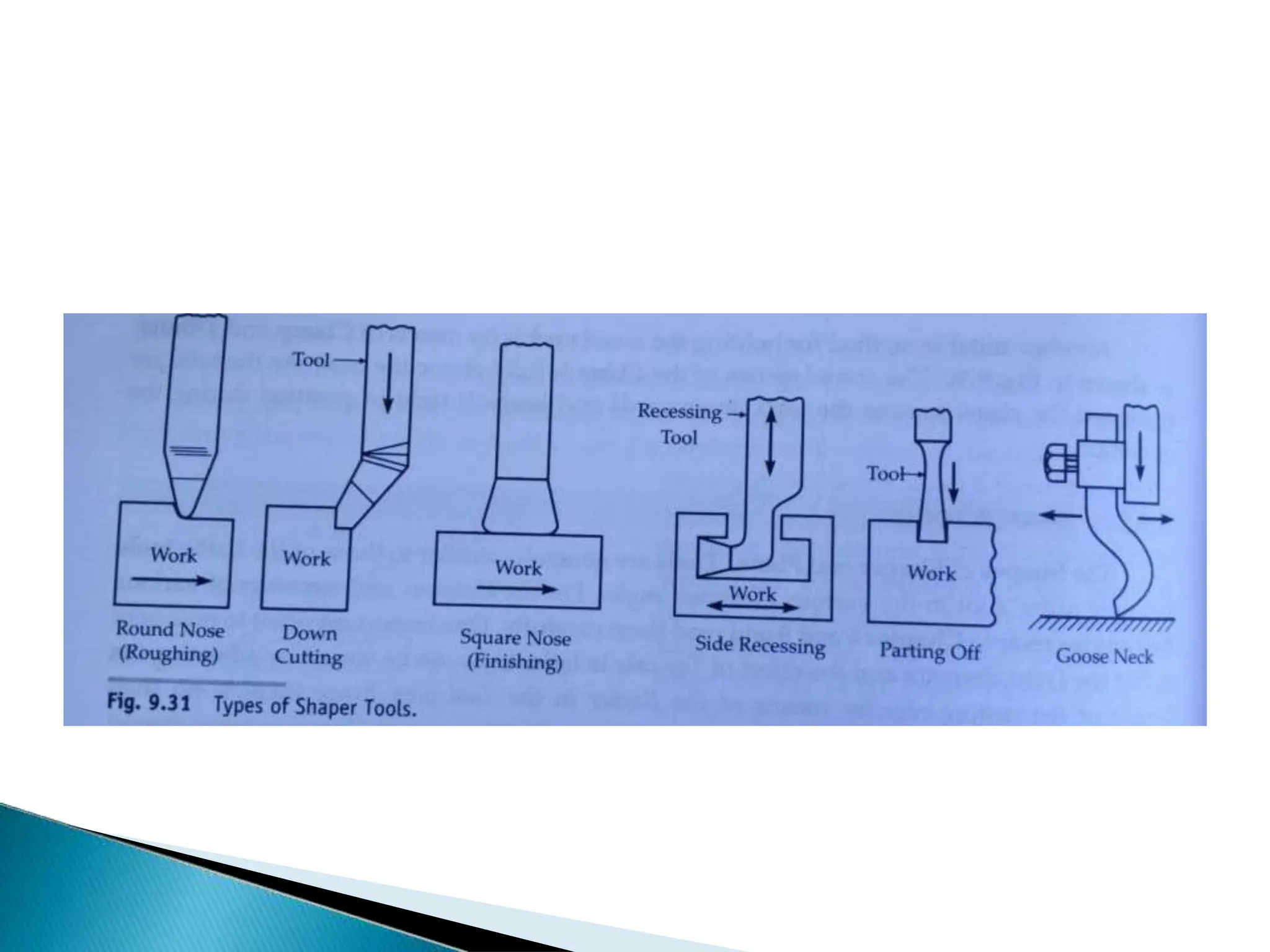
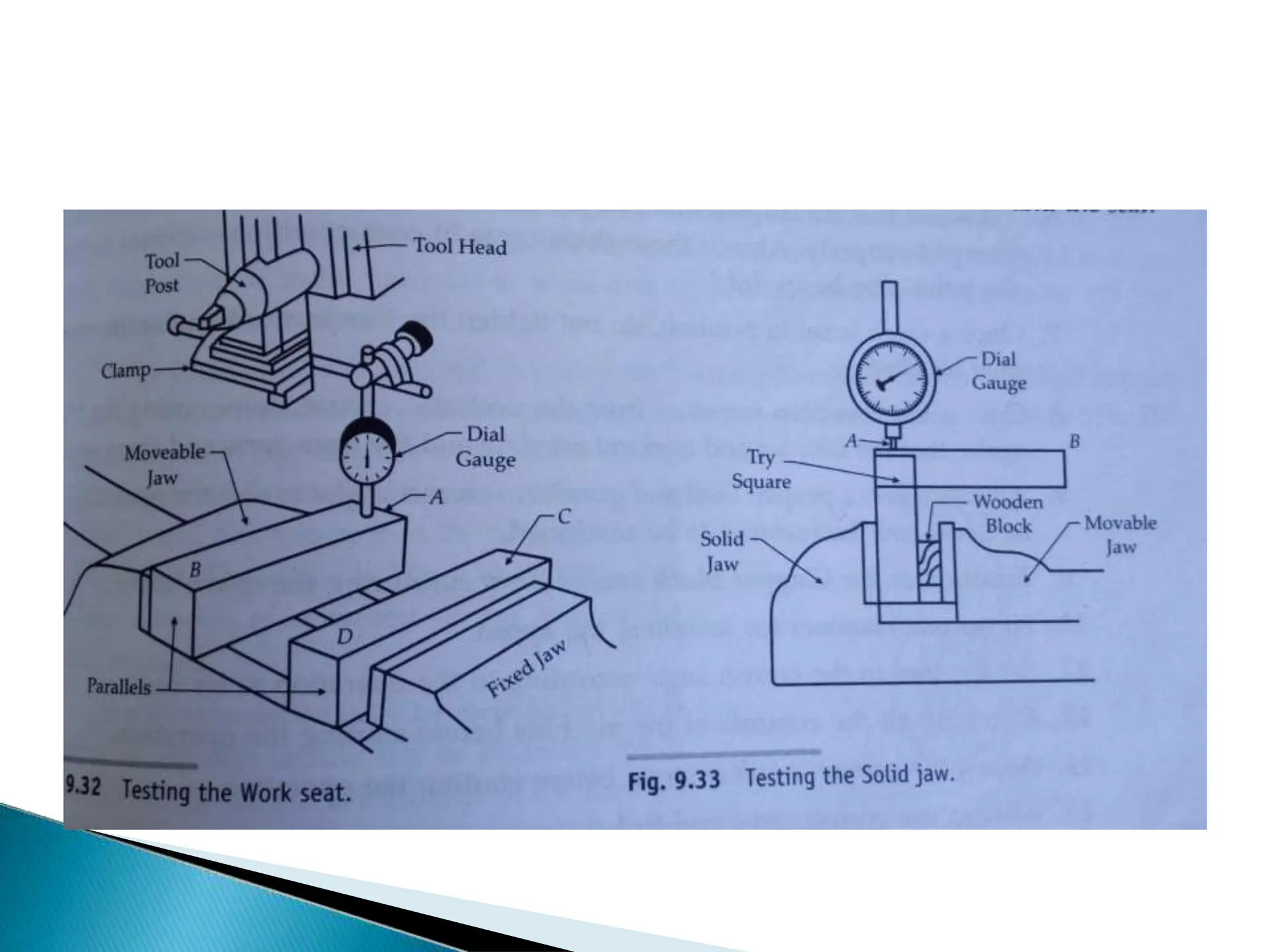

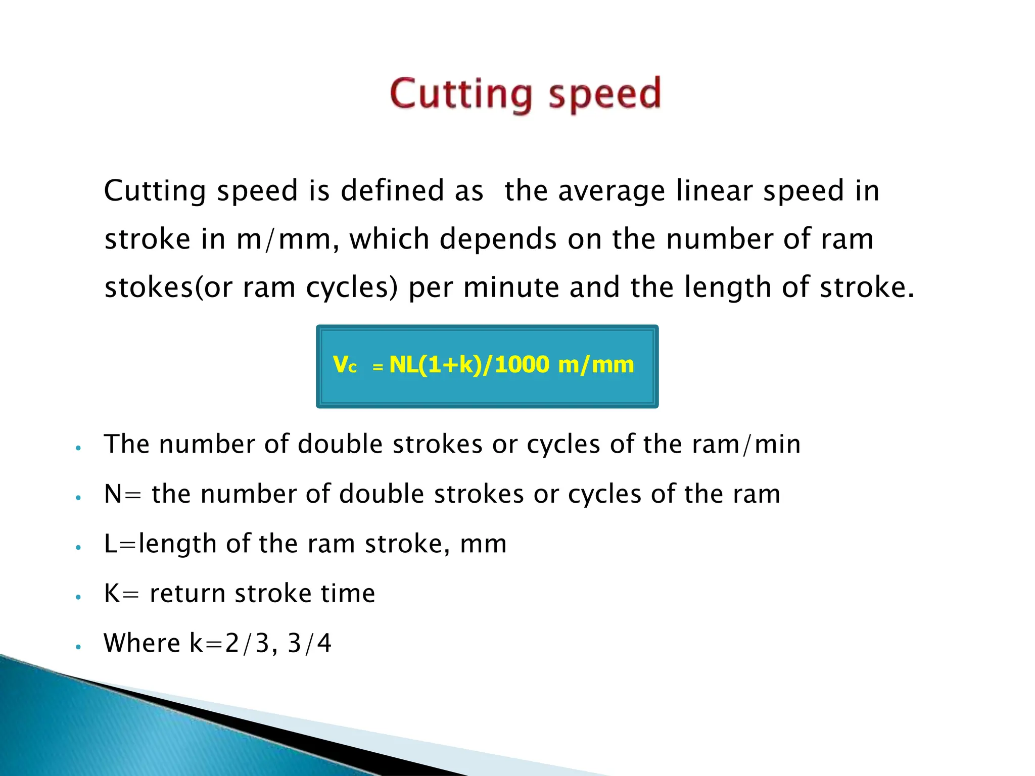

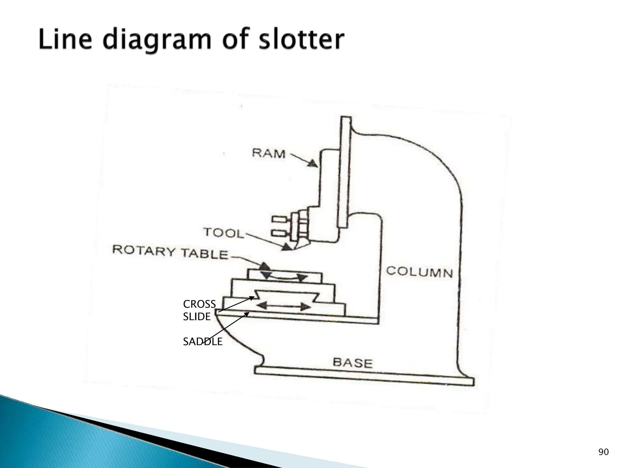
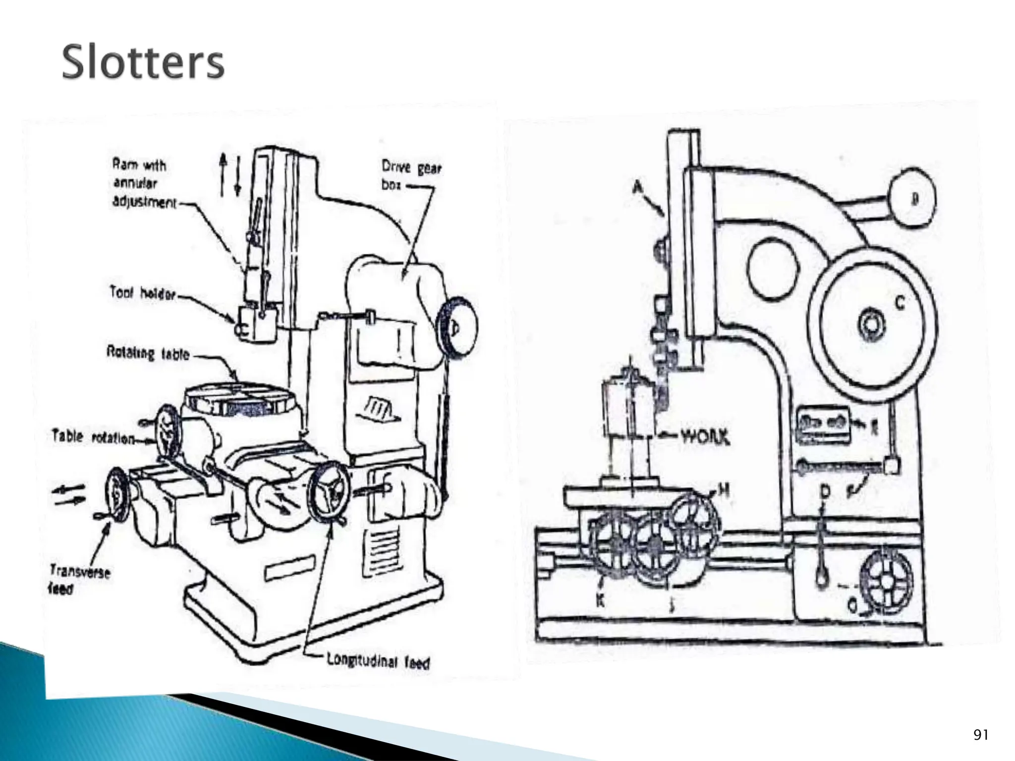
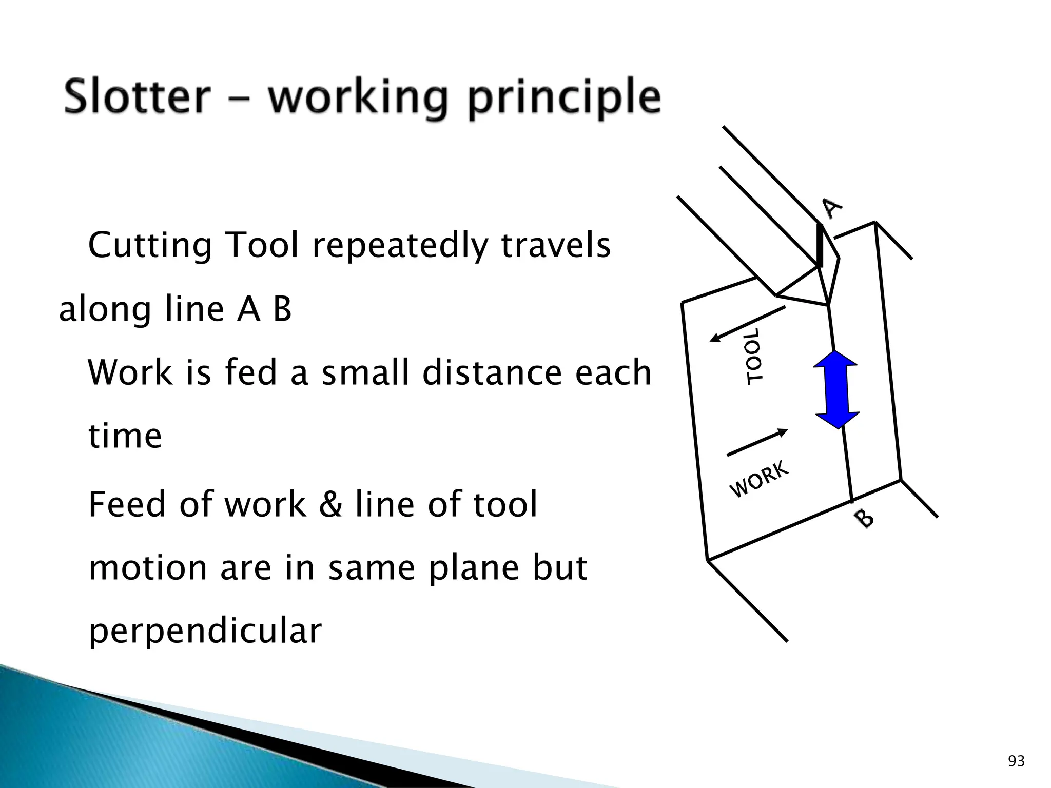

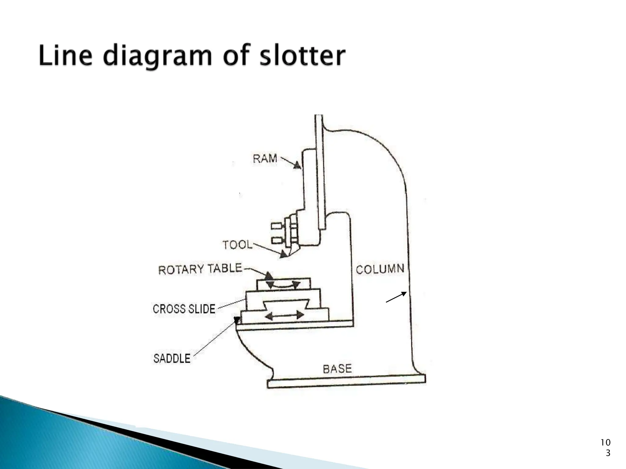
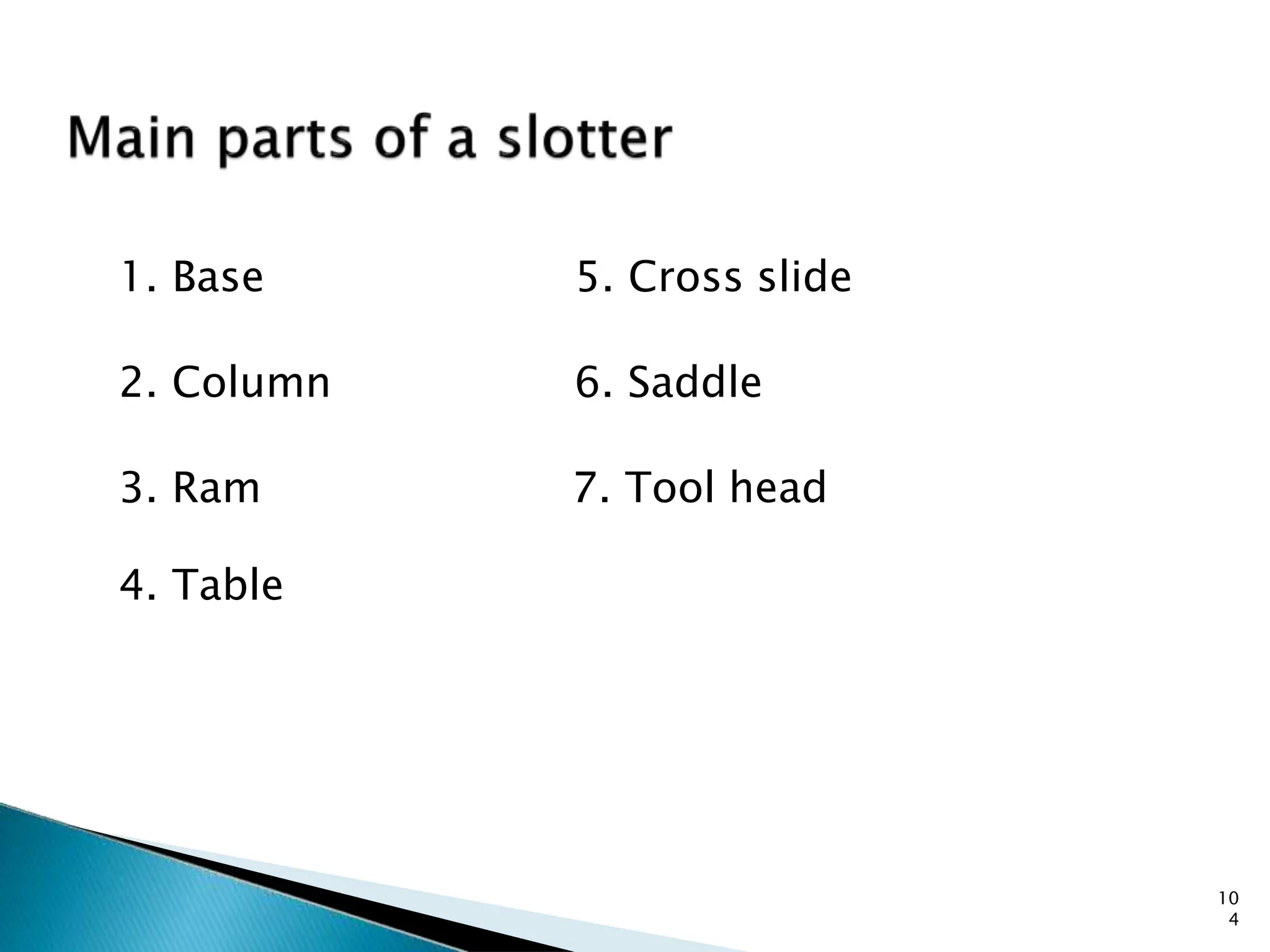

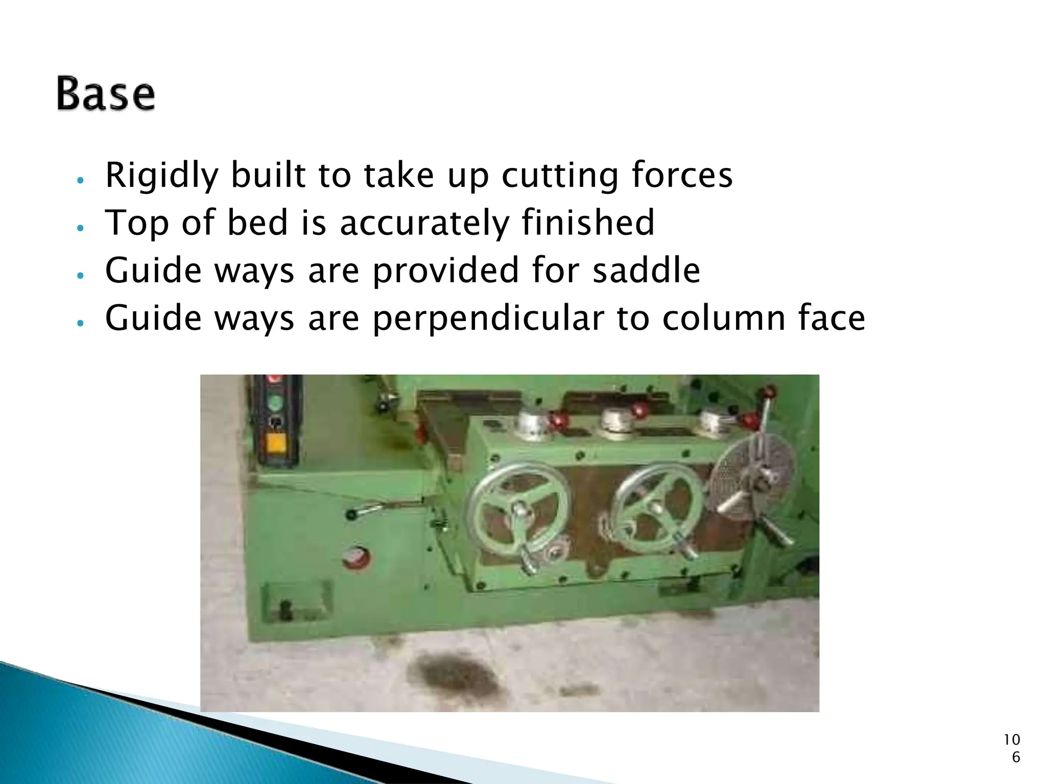
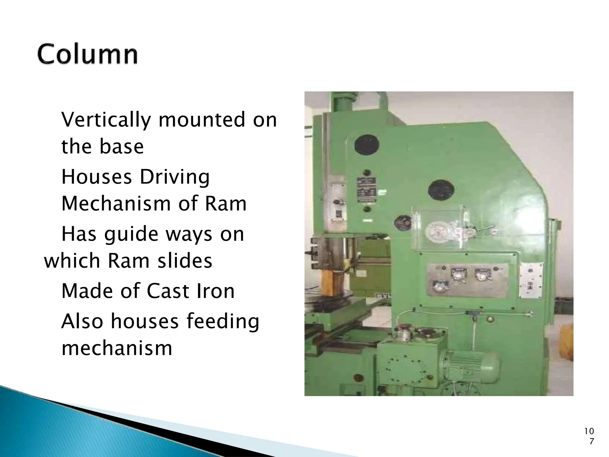
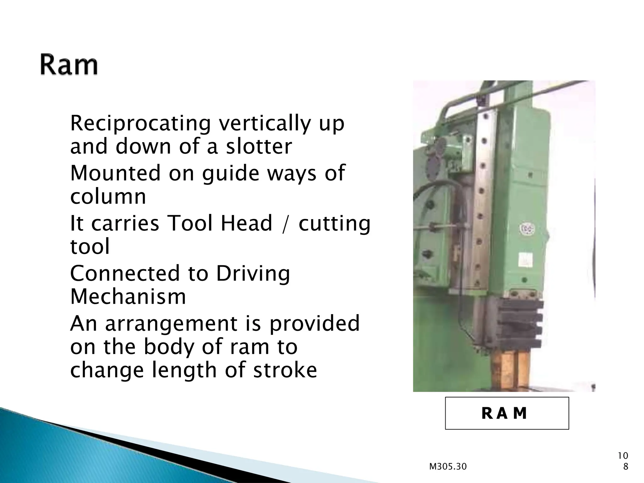
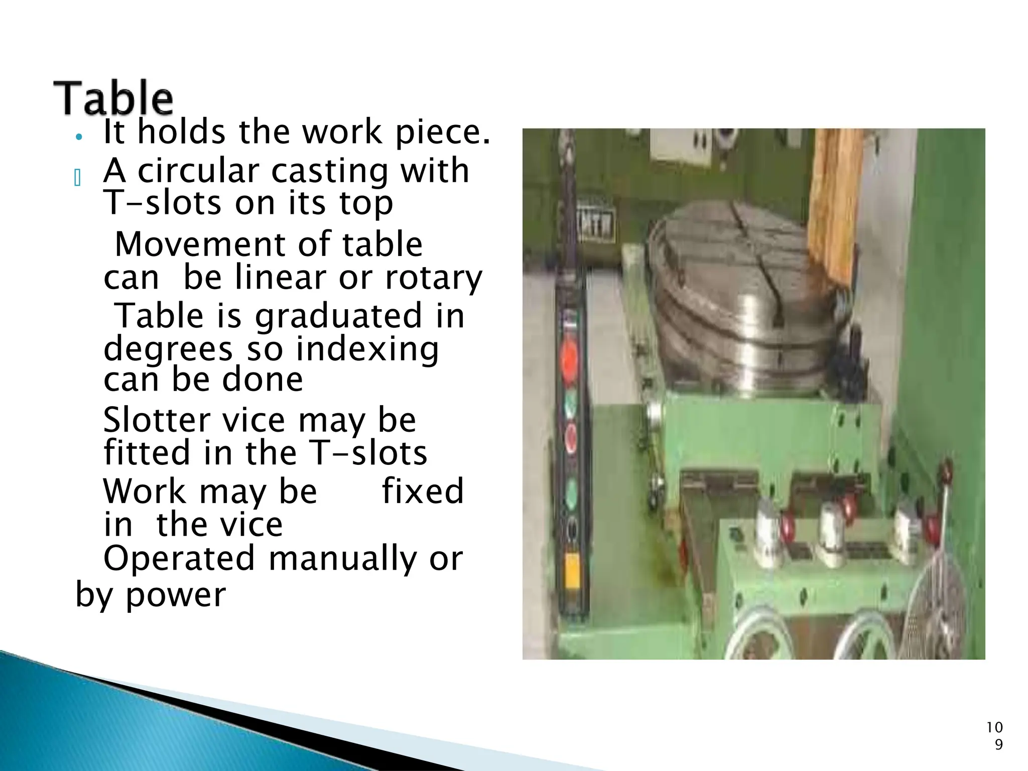


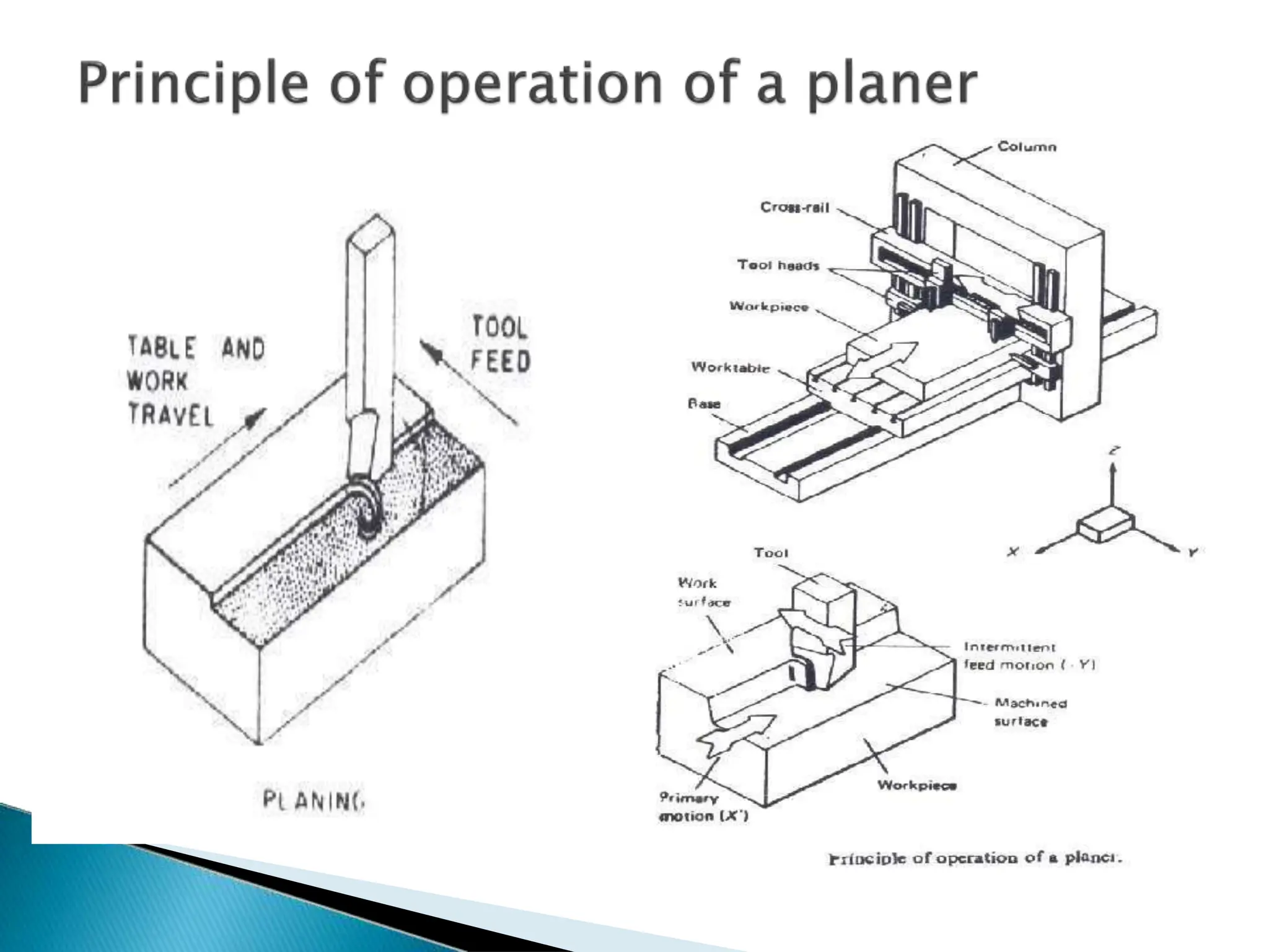
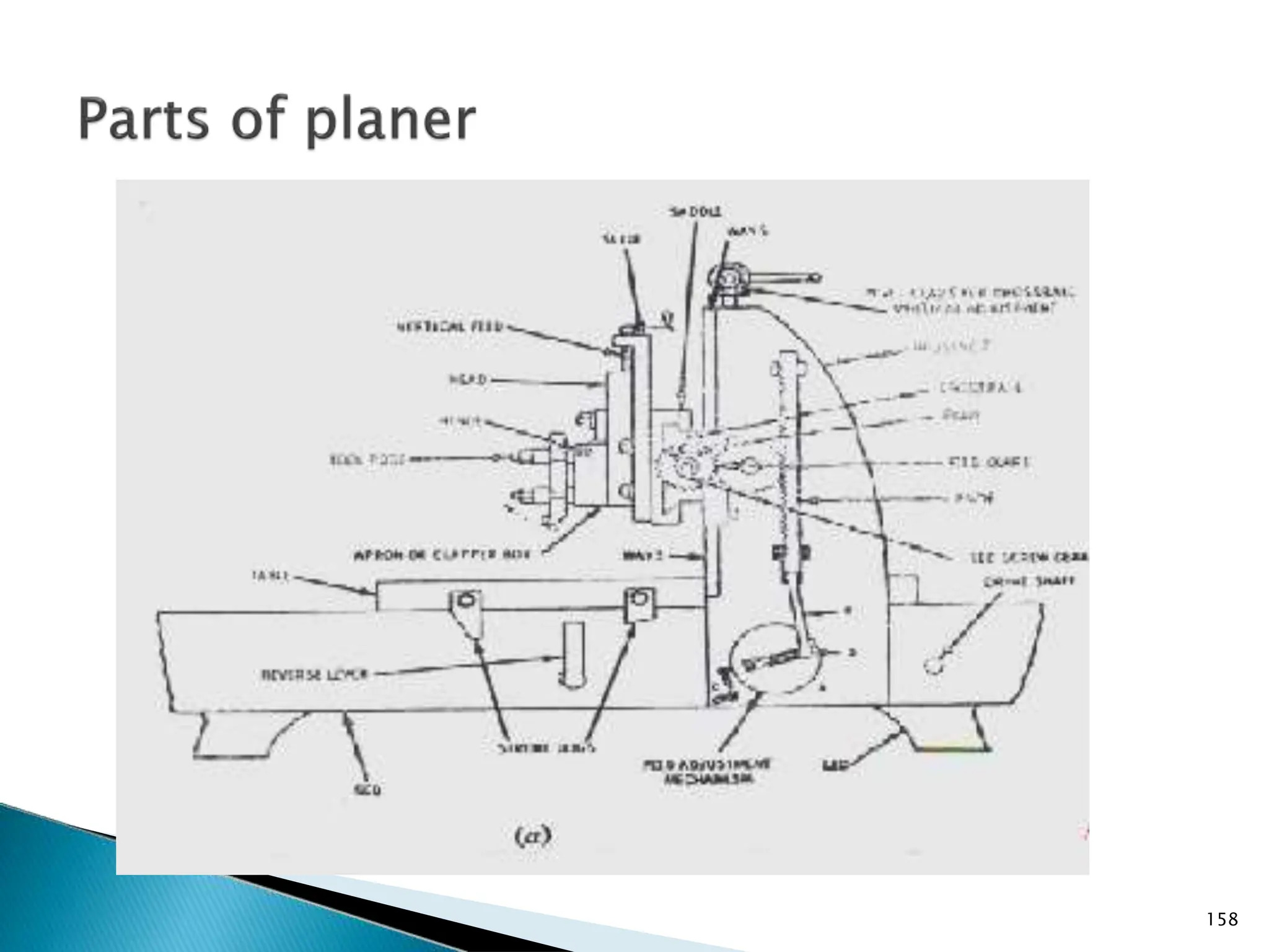
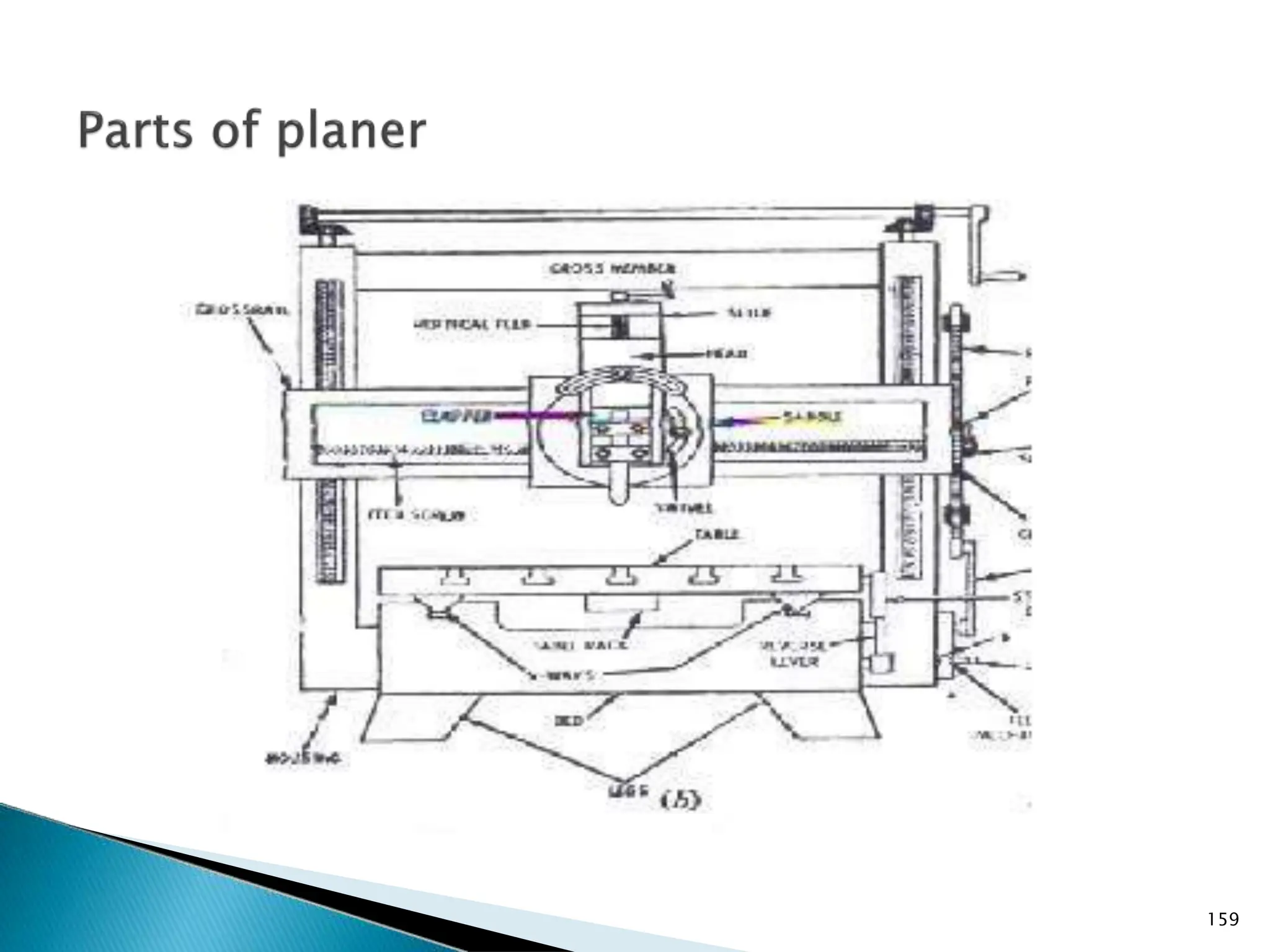
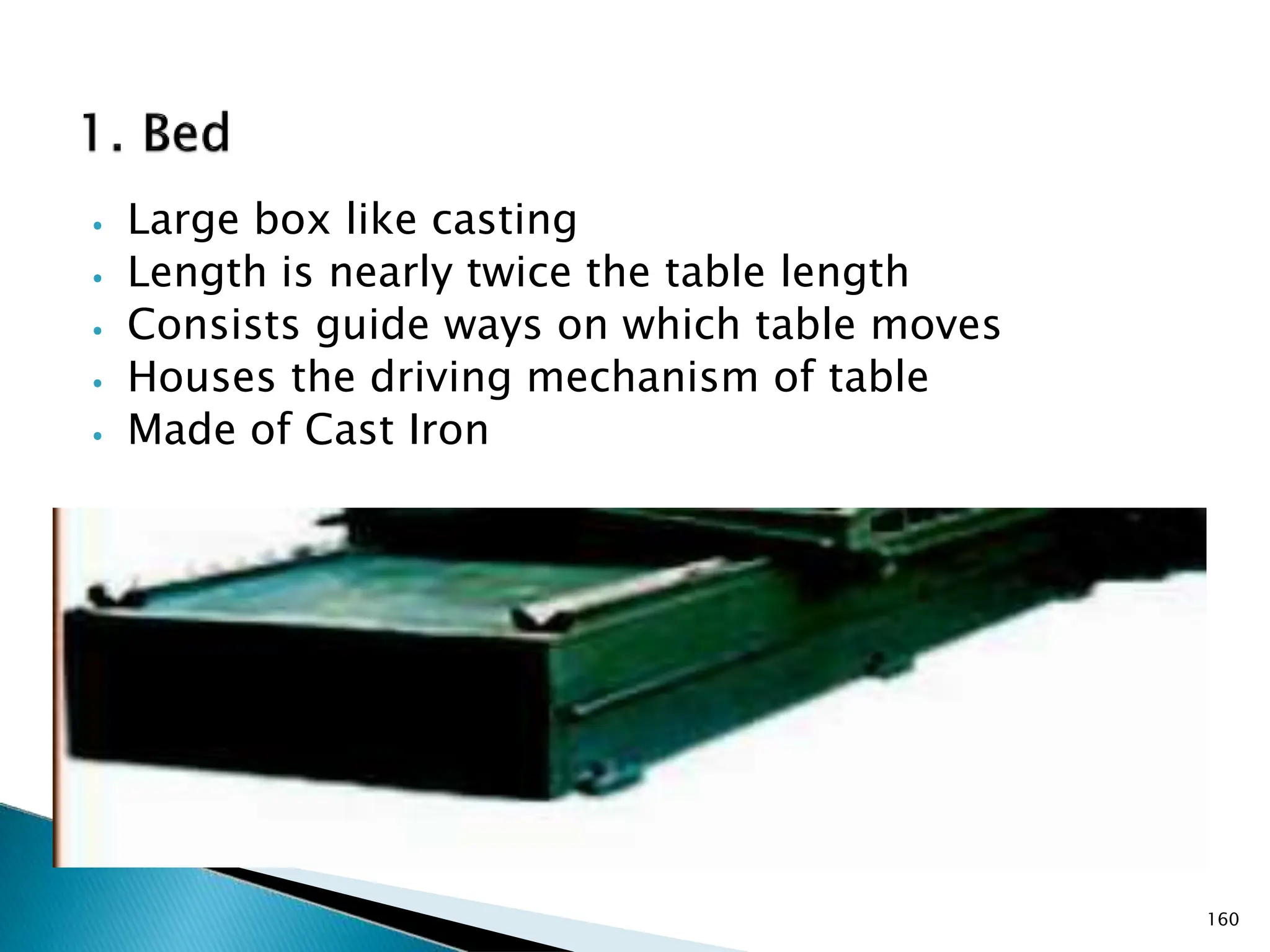
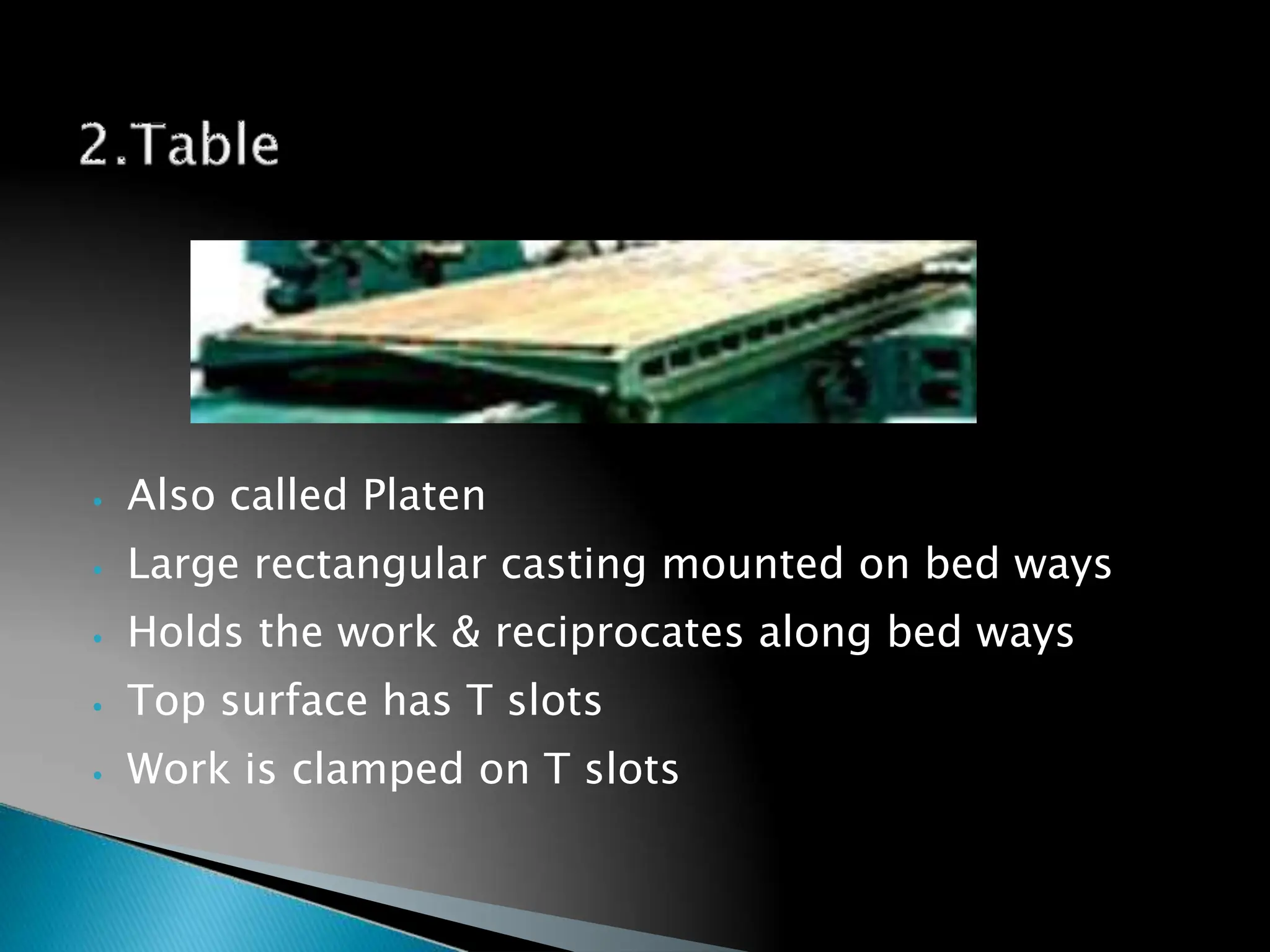


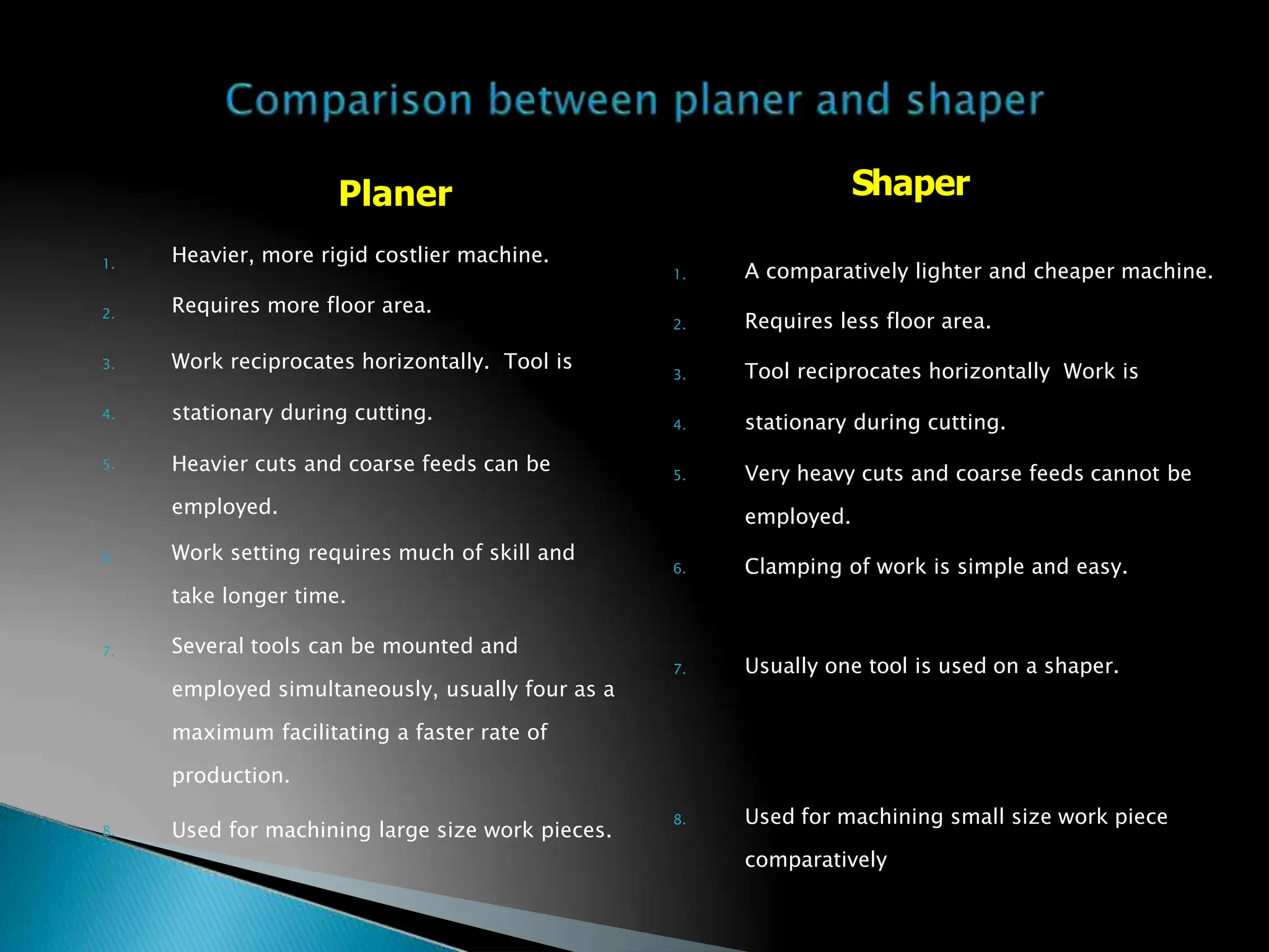
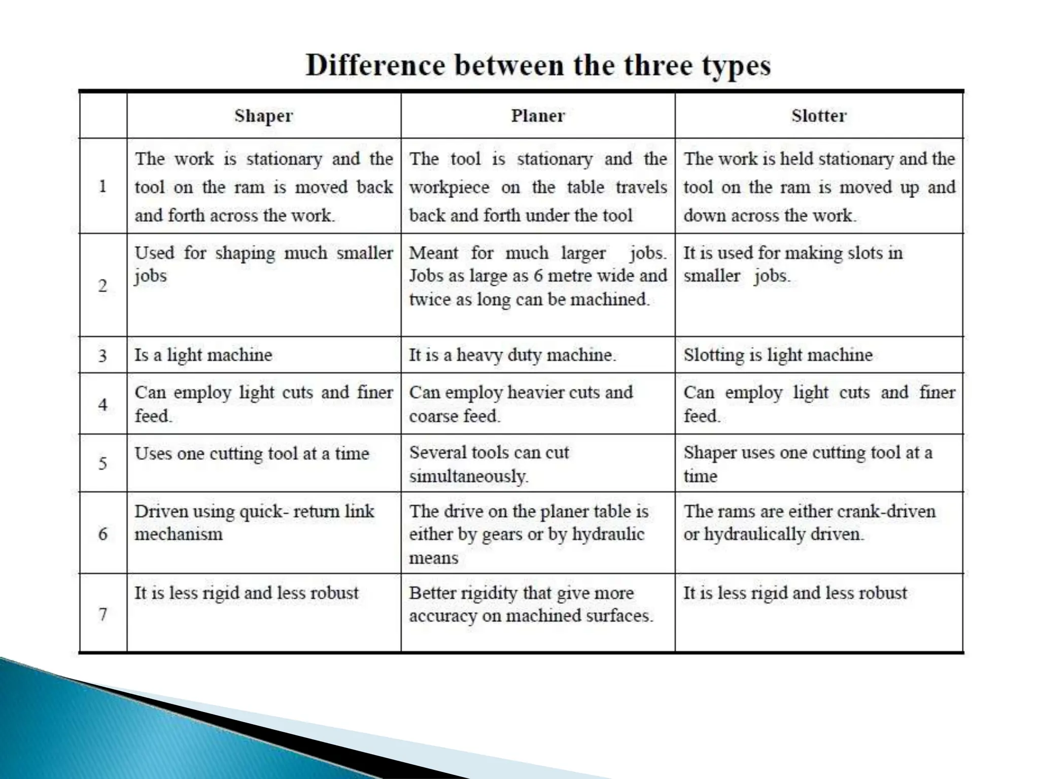

The document details the specifications and operational principles of a shaper machine, which produces flat surfaces via a reciprocating cutting tool. It outlines various types of shapers, their components, driving mechanisms, and the machining processes they perform, including horizontal, vertical, and angular shaping. Additionally, it compares shapers to slotting machines, highlighting design differences and application contexts.


