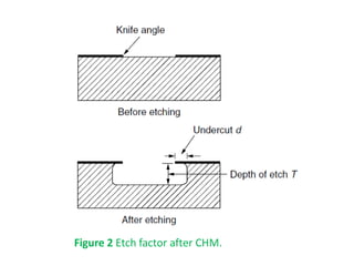
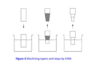
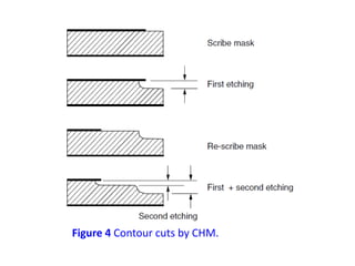
Chemical milling (CHM) is a process that uses controlled chemical dissolution to remove material from a workpiece. It involves masking areas not to be removed, then immersing the workpiece in an etching solution to dissolve the exposed material. Key steps are masking, scribing the mask to expose areas for etching, immersing in etchant, and removing the mask. Factors like etchant type/concentration, temperature, material properties, and process parameters influence the etch rate and surface finish. With proper controls, CHM can produce pockets, contours and complex shapes to tight tolerances and surface roughness of 0.1-0.8 μm.
Electro-chemical machining (ECM) is a non-traditional machining process that removes metal by dissolving it in an electrolyte with the use of electric current. In ECM, the workpiece acts as an anode and is dissolved by the electrolyte, while a tool with the desired shape acts as a cathode. Key factors in ECM include the electrolyte, which carries current and removes dissolved material, the tool and workpiece materials, and a DC power supply. ECM can machine hard metals and complex shapes with high accuracy and no tool wear. Common applications of ECM include machining turbine blades, aerospace components, and other difficult-to-machine metals.
Chemical machining or chemical milling uses acidic or alkaline solutions to dissolve materials in a controlled manner for milling or blanking parts. Maskants that are chemically resistant are used to protect surfaces that should not be machined. Etchants like FeCl3 or HNO3 dissolve metals into metallic salts. Process parameters like the selection of etchant and maskant are important. Chemical machining allows for complex contours and hard materials to be machined with a high surface finish and low tooling costs but the process is generally slow. Applications include undercuts, eliminating recast layers, and thinning materials.
Non-traditional manufacturing processes is defined as a group of processes that remove excess material by various techniques involving mechanical, thermal, electrical or chemical energy or combinations of these energies
The document discusses cutting tools and their properties. It describes different types of cutting tool materials like high-speed steel, cemented carbides, ceramics, and diamond. It explains cutting tool nomenclature and defines terms like rake angle, clearance angle, nose, and flank. It also discusses factors that affect tool life like cutting conditions, work material properties, and tool material.
Unit 5 -RECENT TRENDS IN NON-TRADITIONAL MACHINING PROCESSESShanmathyAR2
Recent developments in non-traditional machining processes, their working principles, equipments,
effect of process parameters, applications, advantages and limitations. Comparison of non-traditional
machining processes.
1. Electrochemical grinding (ECG) is a non-traditional machining process that removes electrically conductive material by grinding with a negatively charged abrasive wheel, electrolyte fluid, and a positively charged workpiece. Materials are removed through electrolysis and some abrasion, leaving a smooth burr-free surface.
2. ECG can machine very hard and brittle materials more effectively than traditional processes due to generating little heat. Key parameters that affect the material removal rate include the abrasive wheel properties, workpiece material and surface, machining conditions, electrolyte type and properties, and voltage applied.
3. ECG provides advantages like burr-free surfaces, less work hardening, higher precision
The document discusses three mechanical energy-based machining processes: abrasive jet machining (AJM), water jet machining (WJM), and ultrasonic machining (USM). In AJM, a high-speed stream of abrasive particles erodes material from the workpiece. WJM uses a high-velocity water jet to convert kinetic energy into pressure that removes small chips. USM forces an abrasive slurry against the workpiece using a vibrating tool to remove extremely small chips. Key parameters for each process include abrasive properties, pressure, velocity, vibration frequency, and more. Each method can machine hard materials and provides advantages like avoiding heat, being noiseless, or enabling intricate shapes.
Advanced machining processes
Utilize chemical, electrical, and high-energy beams
Situations where traditional machining processes are
unsatisfactory or uneconomical:
– Workpiece material is too hard, strong, or tough.
– Workpiece is too flexible to resist cutting forces or too difficult
to clamp.
– Part shape is very complex with internal or external profiles
or small holes.
– Requirements for surface finish and tolerances are very high.
– Temperature rise or residual stresses are undesirable or
unacceptable.
So to eliminate this disadvantages non conventional machines can be used
This document discusses sheet metal processes and operations. Sheet metal is metal formed into thin, flat pieces that can be cut and bent into various shapes. Common materials for sheet metal include steel, aluminum, copper, and other metals. Key sheet metal operations covered include shearing, blanking/punching, bending, drawing, deep drawing, stamping, and others. Factors that influence these operations such as punch and die design, clearance, and lubrication are also addressed.
Wire cut EDM uses a thin wire as the electrode to cut complex shapes into difficult-to-machine materials like tungsten carbide. The process involves using a CNC machine to move the workpiece near the vertically moving wire while a dielectric fluid flows between them. Electrical sparks erode small amounts of material from both the wire and workpiece, with the fluid flushing away debris. Key aspects that enable the precision process include a servo system to maintain a small gap, water-based dielectric fluid for initiating sparks and cooling, and characteristics of the consumable wire electrode.
Plasma arc machining uses ionized gas (plasma) to cut metals. It can cut materials that are difficult to cut with traditional techniques due to high thermal conductivity and oxidation resistance. The process involves generating a pilot arc to ignite the plasma and transferring the arc to the workpiece to melt and vaporize the metal, which is removed by the high-velocity gas. Plasma arc machining produces high-quality cuts at maximum productivity and is suitable for automated cutting applications.
The document discusses various unconventional machining processes. It begins with introducing that unconventional machining uses indirect energy like sparks, heat or chemicals rather than direct contact between a tool and workpiece. It then covers different unconventional processes like EDM, laser beam machining, electrochemical machining and their characteristics. The document categorizes unconventional machining processes and provides details on processes like chemical machining, electrochemical grinding and ultrasonic machining. It concludes with discussing advantages and disadvantages of non-conventional machining.
Different types of casting process and its applicationmangal iron
Casting involves pouring liquid metal into molds to form objects. The main types of casting are sand casting, permanent mold casting, centrifugal casting, continuous casting, and investment casting. Sand casting uses sand as the mold material and is inexpensive but less accurate. Permanent mold casting uses reusable metal molds for higher accuracy. Centrifugal casting forms thin-walled cylinders. Continuous casting produces long strips of metal in an automated process. Investment casting creates molds from liquid and is suitable for complex shapes.
Electrochemical grinding (ECG) is a process where a rotating grinding wheel acts as a cathode and the workpiece is the anode. An electrolyte like NaNO3 is used and a voltage is applied, causing material to be removed from the workpiece electrochemically with some additional removal by abrasion from diamond or aluminum oxide particles on the wheel. ECG can machine difficult materials, achieve close tolerances on thin parts without distortion, and offers advantages over conventional grinding like higher removal rates and elimination of burrs. However, it also has higher costs and is limited to electrically conductive materials.
Hybrid manufacturing combines two or more non-traditional manufacturing processes. Electrochemical grinding combines electrochemical machining and grinding. It uses a grinding wheel and electrolytic fluid to remove material from a conductive workpiece. The process produces close tolerances and smooth surfaces. Key advantages are minimal wheel wear and ability to machine hard materials. Applications include machining difficult materials like carbides and composites. Future developments could improve efficiency and surface quality when machining advanced materials.
Electro-chemical machining (ECM) is a non-traditional machining process that removes metal using electrolysis. In ECM, a tool acts as the cathode and the workpiece as the anode. An electrolyte flows between the tool and workpiece, completing the electrical circuit. Metal is dissolved from the workpiece and the tool shape is replicated due to the electrolytic reactions. ECM can machine hard metals and complex shapes with high accuracy and no tool wear. Common applications include machining turbine blades, aerospace components, and molds.
The document summarizes the wire drawing process. Wire drawing is used to reduce the cross-sectional area of wire by pulling it through progressively smaller dies. There are single step and continuous wire drawing machines. Proper lubrication is important for smooth finishes and long die life. Different types of dies and materials are used depending on the type of wire. Automation using programmable logic controllers allows maintaining constant speed and drawing force for high accuracy and reduced labor costs.
Abrasive jet machining uses a high-pressure stream of abrasive particles carried by gas or water to erode material from a workpiece. Key components include an abrasive delivery system, control system, pump, nozzle, and motion system. It can precisely cut hard materials like ceramics and glass. While removal rates are slower than other machining methods, AJM requires no start holes and generates minimal heat or vibration in the workpiece.
This document provides an overview of electrochemical machining (ECM). ECM is a non-conventional machining process that removes metal through an electrochemical process rather than adding it, as in electroplating. In ECM, a tool acts as the cathode and the workpiece the anode, with an electrolyte solution flowing between them. Metal is removed from the workpiece through an electrolysis process governed by Faraday's laws of electrolysis. ECM can machine complex internal and external geometries in hard metals and is well-suited for mass production. Key aspects of ECM covered include the power supply, electrolyte, tool, control system, and principles of operation. Applications and advantages, such as little
Abrasive flow machining is a deburring and surface finishing process that uses abrasive particles mixed in a viscoelastic medium. It can polish internal surfaces, holes, and intersecting holes. The document discusses the need for AFM, abrasive materials used, the one-way, two-way, and orbital classification methods, process parameters like pressure and abrasive size, capabilities like surface finish ranges and tolerances, and applications in aerospace, automotive, die and mold making, and medical industries to improve surfaces, reduce wear, increase performance, and extend component life.
Abrasive water jet machining (AWJM) is a non-traditional machining process that uses a high-pressure stream of water mixed with abrasive particles to erode materials. It works by converting the kinetic energy of the water-abrasive jet into high pressure upon impacting the workpiece surface, removing material when the pressure exceeds the part's strength. The document discusses the AWJM process, including its mechanism of localized erosion, key parameters like water pressure and abrasive flow rate, applications in cutting a wide range of materials, advantages like flexibility and lack of heat, and limitations for hard or thick materials.
Thermal energy based machining processes like electron beam machining (EBM), laser beam machining (LBM), and plasma arc machining (PAM) work by concentrating heat energy on a small area of the workpiece to melt and vaporize material. EBM uses a beam of high velocity electrons, LBM uses a focused laser beam, and PAM uses a high temperature plasma jet, all to remove tiny bits of workpiece material through localized heating and repetition of the process. While each has advantages like precision and lack of mechanical contact, they also have disadvantages like high equipment costs and low material removal rates.
LASER BEAM MACHINING - NON TRADITIONAL MACHININGSajal Tiwari
Laser Beam Machining or more broadly laser material processing deals with machining and material processing like heat treatment, allowing, cladding, sheet metal bending etc. Such processing is carried out utilizing the energy of coherent photons or laser beam, which is mostly converted into thermal energy upon interaction with most of the materials. Nowadays, the laser is also finding application in regenerative machining or rapid prototyping as in processes like stereolithography, selective laser sintering etc. Laser stands for light amplification by stimulated emission of radiation. The underline working principle of a laser was first put forward by Albert Einstein in
1917 through the first industrial laser for experimentation was developed around the 1960s. The laser beam can very easily be focused using optical lenses as their wavelength ranges from half a micron to around 70 microns. The focused laser beam as indicated earlier can have power density in excess of 1 MW/mm2 . As laser interacts with the material, the energy of the photon are absorbed by the work material leading to a rapid substantial rise in local temperature. This, in turn, results in melting and vaporization of the work material and finally material removal.
Electrochemical grinding (ECG) is a process that combines electrolytic activity and physical material removal using electrically charged abrasive wheels. It produces burr-free parts without heat or mechanical stresses. ECG removes mostly metal electrolytically (90%) and some mechanically (10%) from the wheel. It can achieve smooth surfaces down to 0.1-0.2 μm roughness on hard metals like tungsten carbide. Process parameters like voltage, current density, feed rate, and electrolyte composition control the metal removal rate and precision. ECG finds applications for grinding carbide tools, turbine blades, and other precision parts.
1. Laser beam machining is a non-conventional machining process that uses a laser beam directed by mirrors to remove material from a workpiece through thermal energy.
2. The laser beam machining process involves using a power supply to energize flash lamps, which produce intense light to energize lasing materials like ruby crystals. The coherent laser light is focused by lenses onto the workpiece.
3. Laser beam machining can machine any material with high accuracy and a small heat affected zone. It is used to make small holes and for applications like micro-drilling, welding specialty materials, and medical procedures.
The AJM process involves removing material from a workpiece using abrasive particles carried by a high-velocity gas stream. The abrasive particles impact the workpiece surface at high velocities, causing brittle fractures and removing small fragments of material. AJM can machine hard and brittle materials and reach difficult internal areas due to the flexible hose used to direct the abrasive stream. It generates less heat than conventional machining and does not require direct tool-workpiece contact. Common applications include cutting glass and ceramics, deburring metal parts, and cleaning or dressing grinding wheels.
Chemical machining is a nontraditional machining process that removes metal from a workpiece by immersing it in a chemical solution. The process involves masking areas of the workpiece to be protected, then etching away the exposed material with an acidic or alkaline solution. Chemical machining can produce complex parts with close tolerances and is used for applications such as MEMS and semiconductor devices that require micro-scale features. The key steps of chemical machining include cleaning the workpiece, applying a photoresist mask, exposing the mask to create the desired pattern, etching, and removing the mask.
Chemical Machining Process and its Types.Umar Saeed
The detail overview on how chemical machining removes material to produce high quality parts, its different processes and types. I also includes figure and video which will help you understand the process easily.
The document discusses abrasive jet machining (AJM), including its working principle, components, process parameters, applications, advantages, and disadvantages. AJM works by using a high-pressure jet of abrasive particles carried by gas to erode material from the workpiece surface. Key parameters that affect the machining include abrasive type and size, gas pressure and flow rate, nozzle design, and stand-off distance between nozzle and workpiece. AJM can machine hard and brittle materials and create complex shapes, though it has low material removal rates and issues with accuracy due to jet divergence.
CHEMICAL MACHINING - NON TRADITIONAL MACHININGSajal Tiwari
The chemical machining processes include those wherein material removal is accomplished by a chemical reaction, sometimes assisted by electrical or thermal energy applications. This group includes chemical milling, photochemical machining, and thermo-chemical machining.
It's a presentation prepared by me on Chemical milling a type of non traditional machining process to help the students to know the key concept about it.
This document provides information about chemical machining from Atria Institute of Technology. It discusses that chemical machining uses chemicals to remove metal by immersing workpieces in chemical solutions. It then describes the working principle of chemical etching and provides schematics of the chemical blanking and chemical milling processes. The document outlines the main steps of each process and notes advantages like burr-free components and ability to machine difficult materials, as well as limitations like slow removal rates. It concludes by discussing applications in precision manufacturing where close tolerances and micron-level finishes are required.
The document discusses a study to reduce variation in the outer diameter of driven plates produced at an automotive clutch manufacturing company. The objectives are to reduce scrap, increase quality, and reduce costs. The driven plates are made through operations like blanking and piercing. Variation occurs after these operations, affecting the outer diameter dimension. The document reviews factors that can influence variation in blanking processes, like punch and die clearance, geometry, and material properties. It aims to analyze how these parameters impact the outer diameter variation after blanking and piercing of the driven plates.
The document discusses challenges and guidelines for printing solder paste with step stencils. It analyzes how factors like squeegee speed, pressure, angle, and material affect the amount of paste residue near step edges. Testing showed circular apertures near steep step downs had lower transfer efficiency than oblong apertures due to more residue. Guidelines recommend reducing speed, increasing pressure, changing the angle to 45°, and using a polymer squeegee to minimize residue for consistent paste transfer. Apertures far from step edges showed high transfer efficiency regardless of geometry or step height.
This document provides information on advanced manufacturing processes called micro machining processes. It discusses three specific processes: diamond micro machining (DMM), ultrasonic micro machining (USMM), and micro electro discharge machining (MEDM). The document provides details on each process, including principles of operation, applications in manufacturing small or precise components, and comparisons of the processes. It focuses on the use of these micro machining processes for cutting hard and brittle materials with high precision and minimal subsurface damage.
Abrasive jet machining is a non-traditional machining process that removes material by directing a high-velocity stream of abrasive particles carried by a gas through a nozzle onto a workpiece. The abrasive particles impact the workpiece surface at speeds up to 300 m/s, removing material through micro-cutting and brittle fracture. Key aspects of the process include the abrasive particles (usually aluminum oxide or silicon carbide around 50 microns in size), gas propulsion system, abrasive feeder, mixing chamber and nozzle (made of tungsten carbide). Abrasive jet machining can efficiently machine intricate shapes in hard, brittle materials like ceramics and glass with low heat impact.
Study of sliding wear rate of hot rolled steel specimen subjected to Zirconia...IJERA Editor
Wear is nothing but loss of material by usage. In a mechanical industry mechanical components will operate
under severe load, temperature and high speeds. Under such a type of situation, when metal to metal contact take
place the surfaces that comes in contact is subjected to wear. These should be considered as a serious affair in an
industry because if the process of wear continues it can reduce service life of the component and also to the
entire mechanical system to which the component has been used. In the light of the above the present work
mainly deals with the study of wear behavior of hot rolled steel with and without zirconia coating on the contact
surface and the effect of zirconia coating with varying thickness.
Abrasive jet machining uses compressed air or gas to propel abrasive particles at high velocities towards a workpiece. The abrasive particles remove material through micro-cutting and brittle fracture. Key components of the process include the gas propulsion system, abrasive feeder, machining chamber and AJM nozzle. Process parameters like abrasive type, carrier gas properties, abrasive flow rate and nozzle characteristics influence the material removal rate, surface finish and nozzle wear. AJM can precisely machine hard and brittle materials.
The document discusses trials to address the challenge of applying solder paste into recessed cavities on printed circuit boards (PCBs) using stencil printing. Test vehicles were created with cavities of varying depths (0-750um) containing different component footprints. Two types of solder paste were printed into the cavities using a customized step stencil and squeegee. The solder paste application and coverage was analyzed using automated optical inspection. Type 4 solder paste showed better transfer efficiency and coverage than Type 3. Printing with periodic stencil cleaning produced more consistent results compared to no cleaning, though with slightly lower paste volumes. The trials helped clarify the challenges of solder paste application into cavities using stencil printing and
This document provides an introduction to abrasive jet machining (AJM), a type of non-traditional machining. It explains that AJM involves removing material from the workpiece through the impingement of high-velocity abrasive particles propelled by a gas. The key process parameters that control machining characteristics are described, including the abrasive material, gas used, nozzle design and stand-off distance. Advantages of AJM include obtaining a high surface finish, causing little damage, and enabling machining of heat-sensitive materials. Disadvantages are its lower material removal rate and difficulty achieving accuracy and straight holes.
The document discusses abrasive jet machining, which uses a high-velocity stream of abrasive particles carried by compressed air or gas to erode material through micro-cutting and brittle fracture. It describes the process, components, process parameters like abrasives, carrier gas, and nozzle used. Applications include cutting brittle materials like glass, ceramics, and silicon. Key advantages are cool cutting of heat-sensitive materials and high surface finish quality.
This document describes an experiment to study the effects of cutting conditions on surface roughness of a turned part. It discusses the objective, equipment used including a lathe machine and surface roughness measuring instrument. The main factors that influence surface roughness are cutting speed, feed rate, depth of cut, tool geometry and wear. Higher depth of cut and feed rate increase roughness, while higher cutting speed decreases roughness. The experiment measured roughness at various levels of these factors and discussed the results.
Prediction of Electrical Energy Efficiency Using Information on Consumer's Ac...PriyankaKilaniya
Energy efficiency has been important since the latter part of the last century. The main object of this survey is to determine the energy efficiency knowledge among consumers. Two separate districts in Bangladesh are selected to conduct the survey on households and showrooms about the energy and seller also. The survey uses the data to find some regression equations from which it is easy to predict energy efficiency knowledge. The data is analyzed and calculated based on five important criteria. The initial target was to find some factors that help predict a person's energy efficiency knowledge. From the survey, it is found that the energy efficiency awareness among the people of our country is very low. Relationships between household energy use behaviors are estimated using a unique dataset of about 40 households and 20 showrooms in Bangladesh's Chapainawabganj and Bagerhat districts. Knowledge of energy consumption and energy efficiency technology options is found to be associated with household use of energy conservation practices. Household characteristics also influence household energy use behavior. Younger household cohorts are more likely to adopt energy-efficient technologies and energy conservation practices and place primary importance on energy saving for environmental reasons. Education also influences attitudes toward energy conservation in Bangladesh. Low-education households indicate they primarily save electricity for the environment while high-education households indicate they are motivated by environmental concerns.
Discover the latest insights on Data Driven Maintenance with our comprehensive webinar presentation. Learn about traditional maintenance challenges, the right approach to utilizing data, and the benefits of adopting a Data Driven Maintenance strategy. Explore real-world examples, industry best practices, and innovative solutions like FMECA and the D3M model. This presentation, led by expert Jules Oudmans, is essential for asset owners looking to optimize their maintenance processes and leverage digital technologies for improved efficiency and performance. Download now to stay ahead in the evolving maintenance landscape.
Optimizing Gradle Builds - Gradle DPE Tour Berlin 2024Sinan KOZAK
Sinan from the Delivery Hero mobile infrastructure engineering team shares a deep dive into performance acceleration with Gradle build cache optimizations. Sinan shares their journey into solving complex build-cache problems that affect Gradle builds. By understanding the challenges and solutions found in our journey, we aim to demonstrate the possibilities for faster builds. The case study reveals how overlapping outputs and cache misconfigurations led to significant increases in build times, especially as the project scaled up with numerous modules using Paparazzi tests. The journey from diagnosing to defeating cache issues offers invaluable lessons on maintaining cache integrity without sacrificing functionality.
Generative AI Use cases applications solutions and implementation.pdfmahaffeycheryld
Generative AI solutions encompass a range of capabilities from content creation to complex problem-solving across industries. Implementing generative AI involves identifying specific business needs, developing tailored AI models using techniques like GANs and VAEs, and integrating these models into existing workflows. Data quality and continuous model refinement are crucial for effective implementation. Businesses must also consider ethical implications and ensure transparency in AI decision-making. Generative AI's implementation aims to enhance efficiency, creativity, and innovation by leveraging autonomous generation and sophisticated learning algorithms to meet diverse business challenges.
https://www.leewayhertz.com/generative-ai-use-cases-and-applications/
Supermarket Management System Project Report.pdfKamal Acharya
Supermarket management is a stand-alone J2EE using Eclipse Juno program.
This project contains all the necessary required information about maintaining
the supermarket billing system.
The core idea of this project to minimize the paper work and centralize the
data. Here all the communication is taken in secure manner. That is, in this
application the information will be stored in client itself. For further security the
data base is stored in the back-end oracle and so no intruders can access it.
Applications of artificial Intelligence in Mechanical Engineering.pdfAtif Razi
Historically, mechanical engineering has relied heavily on human expertise and empirical methods to solve complex problems. With the introduction of computer-aided design (CAD) and finite element analysis (FEA), the field took its first steps towards digitization. These tools allowed engineers to simulate and analyze mechanical systems with greater accuracy and efficiency. However, the sheer volume of data generated by modern engineering systems and the increasing complexity of these systems have necessitated more advanced analytical tools, paving the way for AI.
AI offers the capability to process vast amounts of data, identify patterns, and make predictions with a level of speed and accuracy unattainable by traditional methods. This has profound implications for mechanical engineering, enabling more efficient design processes, predictive maintenance strategies, and optimized manufacturing operations. AI-driven tools can learn from historical data, adapt to new information, and continuously improve their performance, making them invaluable in tackling the multifaceted challenges of modern mechanical engineering.
Build the Next Generation of Apps with the Einstein 1 Platform.
Rejoignez Philippe Ozil pour une session de workshops qui vous guidera à travers les détails de la plateforme Einstein 1, l'importance des données pour la création d'applications d'intelligence artificielle et les différents outils et technologies que Salesforce propose pour vous apporter tous les bénéfices de l'IA.
2. 1. Introduction
Chemical milling (CHM) is a controlled chemical
dissolution (CD) of the workpiece material by
contacting with a strong reagent.
Special coatings called maskants protect areas from
which the metal is not to be removed.
The process is used to produce pockets and
contours and to remove materials from parts having
a high strength-to-weight ratio.
3. CHM consists of the following steps:
1. Preparing and pre-cleaning the workpiece surface. This
provides good adhesion of the masking material and assures
the absence of contaminants that might interfere with the
machining process.
2. Masking using readily strippable masks, which are
chemically impregnable and adherent enough to stand
chemical abrasion during etching.
4. 3. Scribing of the mask, which is guided by templates to expose
the areas that receive CHM.
The type of mask selected depends on the size of the
workpiece, the number of parts to be made, and the desired
resolution of details.
Silk-screen masks are preferred for shallow cuts requiring
close dimensional tolerances.
4. The workpiece is then etched and rinsed, and the mask is
removed before the part is finished.
5. During CHM (Fig. 1), the depth of the etch is controlled
by the time of immersion.
In order to avoid uneven machining, the chemicals that
impinge on the surface being machined should be fresh.
The chemicals used are very corrosive and, therefore,
must be handled with adequate safety precautions.
Both the vapours and the effluents must be suitably
controlled for environmental protection.
Agitation of the workpiece and fluid is usual; however,
excessive solution flow may result in channeling, grooves,
or ridges.
Inclination of the workpiece may prevent channeling
from gas bubbles.
7. Typical reagent temperatures range from 37 to 85°C. Faster
etching rates occur at higher temperatures, but must be
controlled within ±5°C of the desired temperature in order
to attain uniform machining.
When mask is used, the machining action proceeds both
inward from the mask opening, laterally beneath the mask
thus creating the etch factor as shown in Fig. 2.
The etch factor is the ratio of the undercut d to the depth of
etch T. This ratio must be considered when scribing the
mask using templates.
A typical etch factor of 1:1 occurs at a cut depth of 1.27 mm.
Deeper cuts can reduce this ratio to 1:3.
The radii of the fillet produced will be approximately equal
to the depth of etch.
9. CHM will not eliminate surface irregularities, dents,
scratches, or waviness.
Tapered cuts and stepped cuts (Fig. 3), can also be produced
without masking the workpiece by controlling the depth and
rate of immersion or withdrawal and the number of
immersions respectively.
Successive steps of mask removal and immersion as shown
in Fig. 4 can achieve stepped cuts.
12. Tooling for CHM
Tooling for CHM is relatively inexpensive and simple to
modify.
Four different types of tools are required:
maskants,
etchants,
scribing templates, and
accessories.
13. Maskants:
Maskants are generally used to protect parts of the
workpiece where chemical dissolution (CD) action is not
needed.
Synthetic or rubber base materials are frequently used.
Table 3.1 shows the different maskants and etchants for
several materials together with the etch rate and etch factor.
14.
15. Maskants should, however, possess the following properties:
1. Be tough enough to withstand handling
2. Adhere well to the workpiece surface
3. Scribe easily
4. Be inert to the chemical reagent used
5. Be able to withstand the heat generated during etching
6. Could be removed easily after etching
7. Inexpensive
16. Multiple coats of maskant are frequently used to increase
the etchant resistance and avoid the formation of pinholes
on the machined surfaces.
When thicker, rougher dip or spray coatings are used,
deeper cuts that require long exposure time to the etchant
can be achieved.
Dip, brush, spray, roller, and electro-coating as well as
adhesive tapes can be used to apply masks.
17. Spraying the mask on the workpiece through silk screen,
on which the desired design is imposed, combines the
maskant application with the scribing operation since no
peeling is required.
The product quality is, therefore, improved as is the
ability to generate finer details.
18. The accuracy obtained for lateral dimensions depends on
the complexity of the masking. Typical tolerances for the
different masks are as follows:
– Cut-and-peel masks ±0.179 mm
– Silk-screen resist ±0.077 mm
– Photoresist ±0.013 mm
19. Etchants:
Etchants (see Table 3.1) are acid or alkaline solutions
maintained within a controlled range of chemical
composition and temperature.
Their main technical goals are to achieve the following:
1. Good surface finish
2. Uniformity of metal removal
3. Control of selective and intergranular attack
4. Control of hydrogen absorption in the case of titanium
alloys
5. Maintenance of personal safety
6. Best price and reliability for the materials to be used in
the construction of the process tank
20. 7. Maintenance of air quality and avoidance of possible
environmental Problems.
8. Low cost per unit weight dissolved
9. Ability to regenerate the etchant solution and/or readily
neutralize and dispose of its waste products
21. Scribing templates
Scribing templates are used to define the areas for
exposure to the chemical machining action.
The most common workpiece scribing method is to cut
the mask with a sharp knife followed by careful peeling of
the mask from the selected areas. Layout lines or simple
templates of metal or fiberglass guide the scribing
process. The etch factor allowance must be included in
any method used for the scribing operation.
The negative (used in PCM) or its layout and the template
or the silk screen must allow for the degree of
undercutting expected during etching.
Figure 3.5 shows numerical control (NC) laser scribing of
masks for CHM of a large surface area.
22. Figure 3.5 Laser cutting of masks for CHM of large surfaces (Tlusty, 1999).
23. Accessories
Accessories include tanks, hooks, brackets, racks, and
fixtures.
These are used for single- or-multiple-piece handling into
and out of the etchants and rinses.
24. Process parameters
CHM process parameters include:
the reagent solution type,
concentration,
properties,
mixing,
operating temperature, and
circulation.
25. The process is also affected by the maskant and its
application. These parameters will have direct impacts on
the workpiece regarding the following:
1. Etch factor (d/T )
2. Etching and machining rate
3. Production tolerance
4. Surface finish
26. To machine high-quality and low-cost parts using CHM, one must
consider:
the heat treatment state of the workpiece,
the grain size and range of the workpiece material,
the size and finish control prior to CHM,
the direction of rolling and
weld joints, and the degree of cold work.
27. Material removal rate
The material removal or etch rate depends upon the
chemical and metallurgical uniformity of the workpiece
and the uniformity of the solution temperature.
As shown in Figs. 3.6 and 3.7, castings, having the largest
grain size, show the roughest surface together with the
lowest machining rate.
Rolled metal sheets have the highest machining rate
accompanied by the best surface quality. Etching rates
were high for hard metals and were low for softer ones.
Generally, the high etch rate is accompanied by a low
surface roughness and, hence, narrow machining
tolerances.
28. Figure 3.6 CHM average roughness of some alloys after removing 0.25 to 0.4
mm (El-Hofy, 1995 ).
29. Figure 3.7 Surface roughness and etch rate of some alloys after
removing 0.25 to 0.4 mm (El-Hofy, 1995).
30. Accuracy and surface finish
In CHM, the metal is dissolved by the CD action. This
machining phase takes place both at the individual grain
surfaces as well as at the grain boundaries.
Fine grain size and homogenous metallurgical structure are,
therefore, necessary, for fine surface quality of uniform
appearance.
Surfaces machined by CHM do not have a regular lay
pattern.
Based on the grain size, orientation, heat treatment, and
previously induced stresses,
31. every material has a basic surface finish that results from
CHM for a certain period of time.
While surface imperfections will not be eliminated by CHM,
any prior surface irregularities, waviness, dents, or scratches
will be slightly altered and reproduced in the machined
surface.
32. The machining rate affects the surface
roughness and hence the tolerance produced.
Generally, slow etching will produce a surface
finish similar to the original one. Figure 3.7
shows typical surface roughnesses for different
materials.
The orientation of the areas being etched with
respect to the rolling direction or the direction
of the grain in the workpiece is also important
for good CHM surfaces. The depth of cut
tolerance increases when machining larger
depths at high machining rates.
33. Aluminum and magnesium alloys can be controlled more
closely than steel, nickel, or titanium alloys. An etching rate
of 0.025 mm/mm with tolerances of ±10 percent of the cut
width can be achieved depending on the workpiece material
and depth of cut.
The surface roughness is also influenced by the initial
workpiece roughness. It increases as the metal ion
concentration rises in the etchant.
For low machining depths, <200 μm, the roughness sharply
increases with the depth of cut, while at higher depths a
slight change in the roughness is evident.
34. Figure 3.7 shows the dependence of the surface roughness
and etch rate on the workpiece material.
Typically, surface roughness of 0.1 to 0.8 μm, depending on
the initial roughness, can be obtained.
However, under special conditions, roughness of 0.025 to
0.05 μm become possible (Machining Data Handbook,
1997).
35. Advantages
The process has the following advantages:
Weight reduction is possible on complex contours that
are difficult to machine using conventional methods.
Simultaneous material removal, from all surfaces,
improves productivity and reduces wrapping.
No burrs are formed.
No stress is introduced to the workpiece, which
minimizes the part distortion and makes machining of
delicate parts possible.
36. A continuous taper on contoured sections is achievable.
The capital cost of equipment, used for machining large
components, is relatively low.
Design changes can be implemented quickly.
A less skilled operator is needed.
37. Tooling costs are minor.
The good surface quality in addition to the absence of burrs
eliminates the need for finishing operations.
Multiple parts having fine details can be machined by the
gang method.
Decorative finishes and extensive thin-web areas are
possible.
There are low scrap rates (3 percent).
38. Limitations
CHM does have limitations and areas of disadvantage:
Only shallow cuts are practical: up to 12.27 mm for sheets and
plates, 3.83 mm on extrusions, and 6.39 mm on forgings.
Handling and disposal of chemicals can be troublesome.
Hand masking, scribing, and stripping can be time-consuming,
repetitive, and tedious.
Surface imperfections are reproduced in the machined parts.
Metallurgical homogeneous surfaces are required for best results.
Deep narrow cuts are difficult to produce.
Fillet radii are fixed by the depth of cut.
Porous castings yield uneven etched surfaces.
39. Welded areas frequently etch at rates that differ from the
base metal.
Material removal from one side of residually stressed
material can result in a considerable distortion.
The absence of residual stresses on the chemically
machined surfaces can produce unfavourable fatigue
strength compared with the processes that induce
compressive residual stresses.
Hydrogen pickup and intergranular attack are a problem
with some
materials.
40. The straightness of the walls is subject to fillet and
undercutting limitations.
Scribing accuracy is limited and complex designs become
expensive.
Steep tapers are not practical.
41. Applications
All the common metals including aluminum, copper,
zinc, steel, lead, and
nickel can be chemically machined. Many exotic
metals such as titanium,
molybdenum, and zirconium, as well as nonmetallic
materials including
glass, ceramics, and some plastics, can also be used
with the process.
CHM applications range from large aluminum
airplane wing parts to
minute integrated circuit chips.
42. The practical depth of cut ranges between 2.54 to 12.27
mm.
Shallow cuts in large thin sheets are of the most popular
application especially for weight reduction of aerospace
components.
Multiple designs can be machined from the same sheet at
the same time.
CHM is used to thin out walls, webs, and ribs of parts that
have been produced by forging, casting, or sheet metal
forming, as shown in Fig. 3.8