Downloaded 190 times
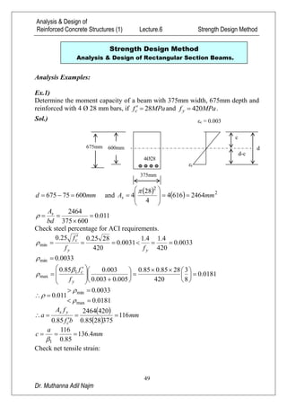
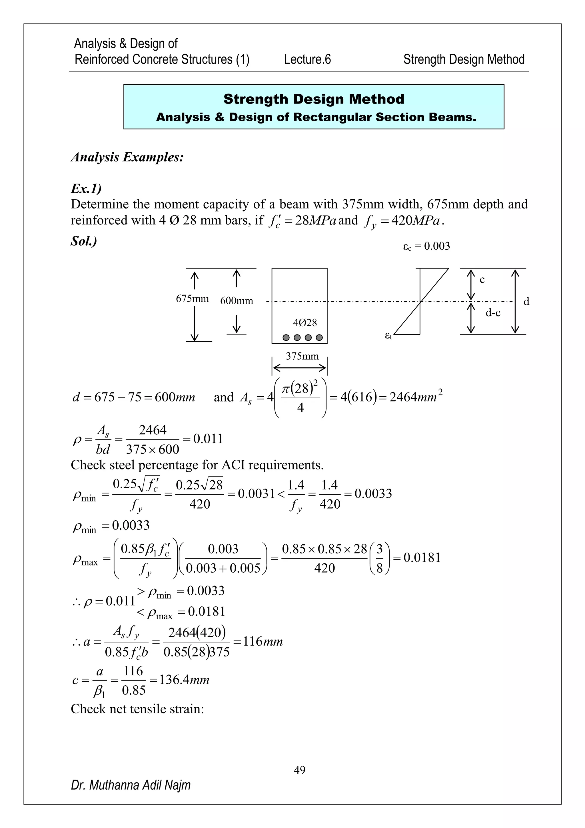
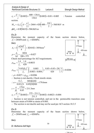

1) The document provides three examples of determining the moment capacity of reinforced concrete beams using the strength design method. The examples calculate steel ratios, check code requirements, and determine moment capacities. 2) Design examples are also provided, including calculating reinforcement needed to resist a given moment and designing a beam to support specific service loads. Optimal dimensions are selected to maximize steel ratio within code limits. 3) Analysis and design procedures for rectangular reinforced concrete beams are demonstrated, including calculation of steel area, reinforcement ratios, strain checks and moment capacities.


![Geotechnical Engineering-II [Lec #4: Unconfined Compression Test]](https://cdn.slidesharecdn.com/ss_thumbnails/4-180930132645-thumbnail.jpg?width=640&height=640&fit=bounds)