Download to read offline
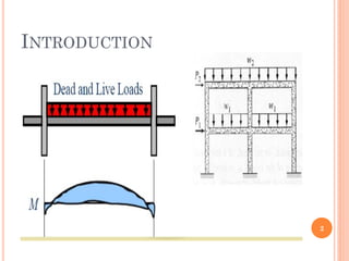
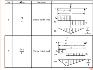
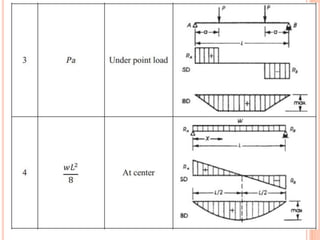
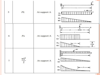
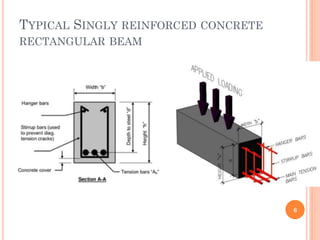
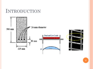
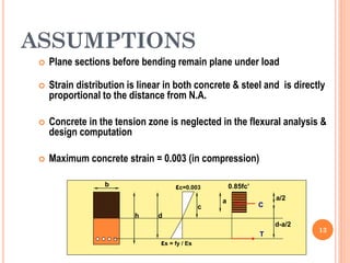
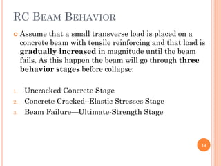
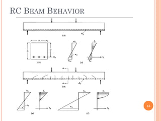
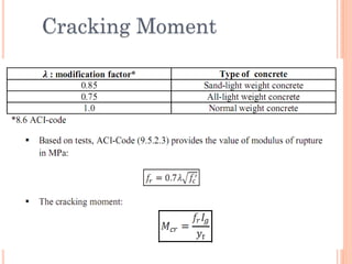
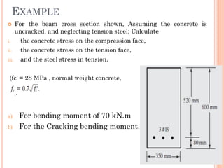
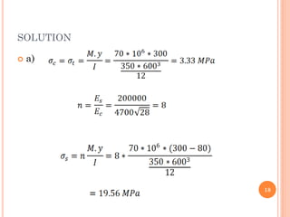
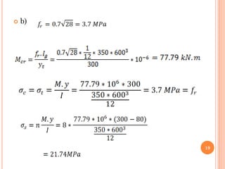
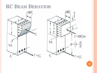
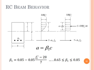
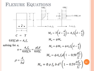

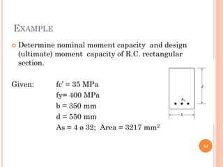
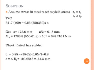
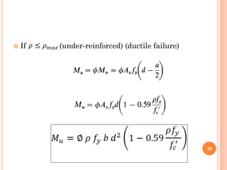
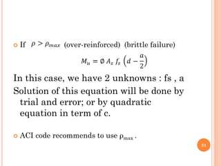
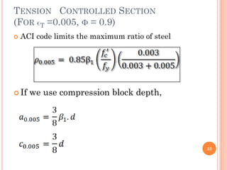
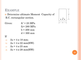


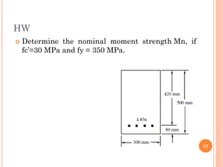
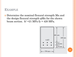
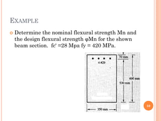
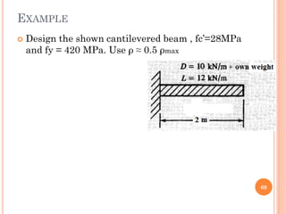

1) The document discusses the flexural analysis and design of reinforced concrete beams. It covers typical beam behavior, stress calculations, flexural equations, and examples of determining nominal moment capacity. 2) Key aspects reviewed include the assumptions in flexural analysis, cracking moment calculations, strain distributions, balanced sections, and code limits on minimum and maximum steel ratios. 3) Practical considerations for concrete dimensions and reinforcement spacing are also addressed. Examples show how to calculate nominal moment strength and design flexural strength for given beam cross-sections.


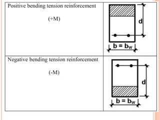
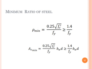
![Geotechnical Engineering-I [Lec #21: Consolidation Problems]](https://cdn.slidesharecdn.com/ss_thumbnails/21-180924141121-thumbnail.jpg?width=640&height=640&fit=bounds)


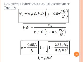
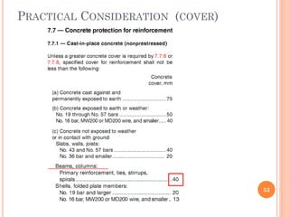
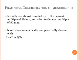
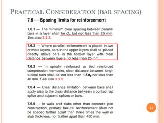
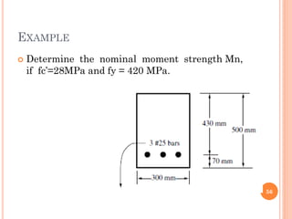
![Geotechnical Engineering-II [Lec #7A: Boussinesq Method]](https://cdn.slidesharecdn.com/ss_thumbnails/7a-181020124807-thumbnail.jpg?width=640&height=640&fit=bounds)