Downloaded 181 times

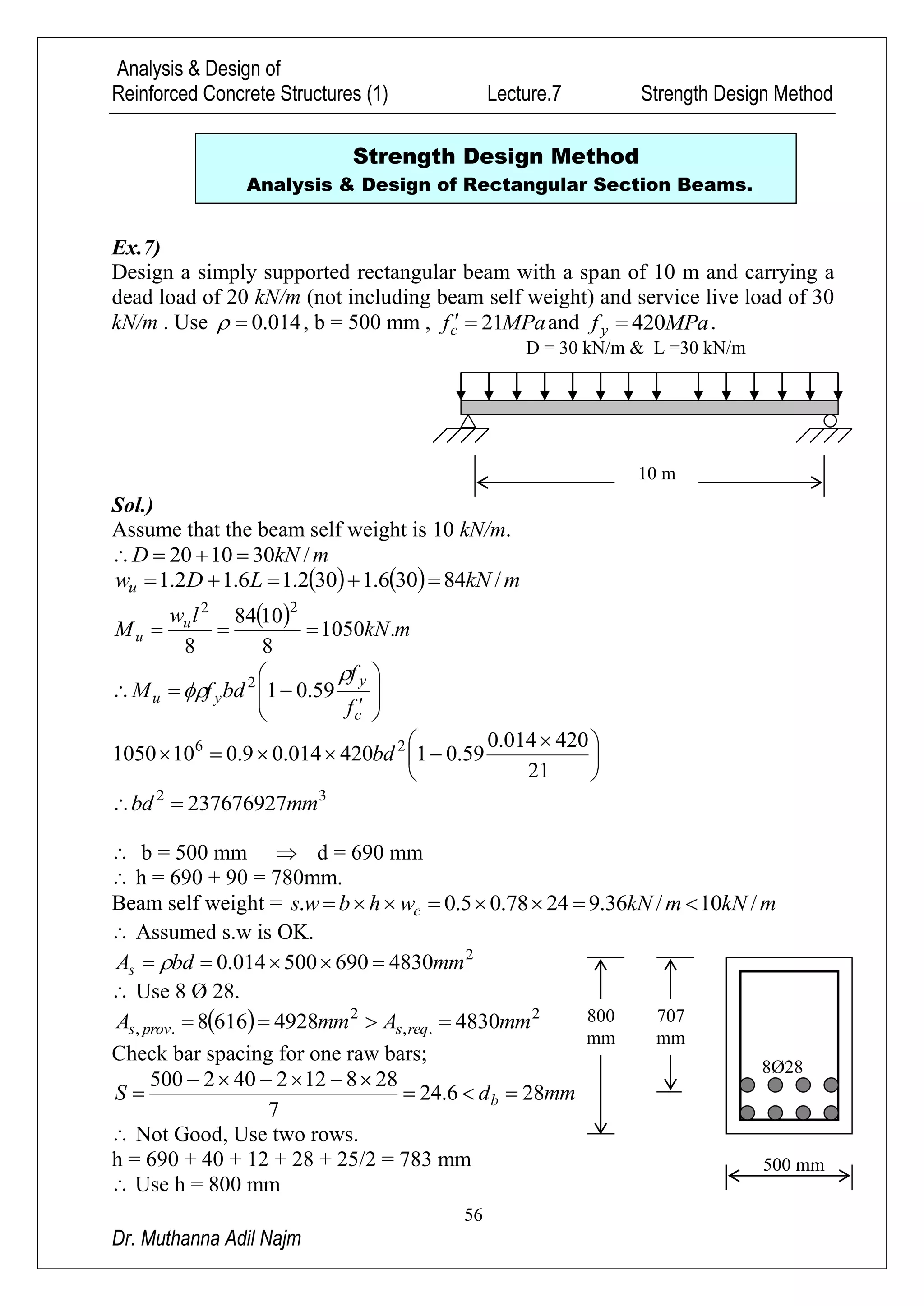
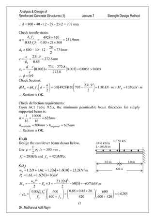
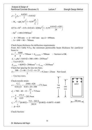
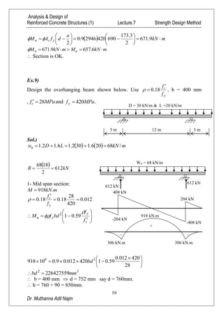
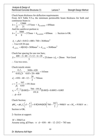
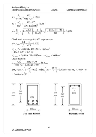
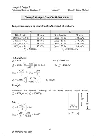

The document analyzes and designs reinforced concrete beams using the strength design method. It provides examples of designing a simply supported rectangular beam, a cantilever beam, and an overhanging beam. The solutions include calculating loads, moments, required reinforcement, checking deflection requirements, and verifying the strength of the designed sections.