Downloaded 684 times
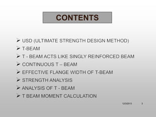
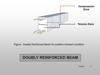
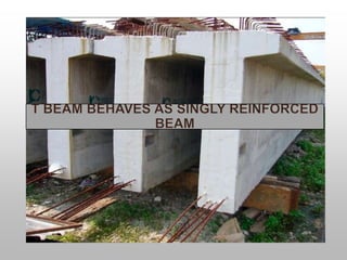
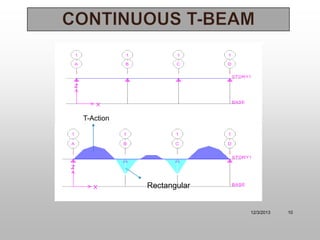
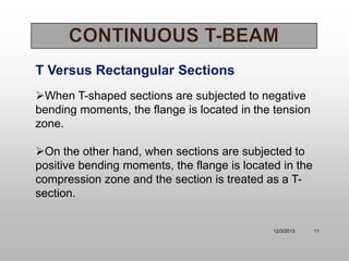
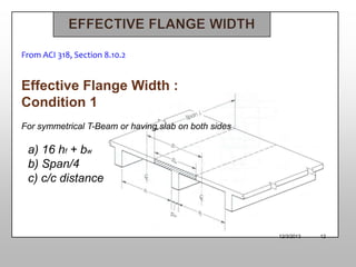
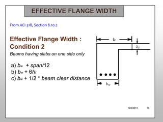
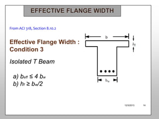
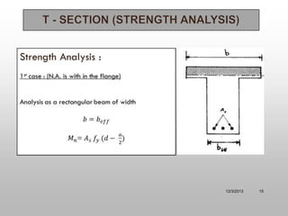
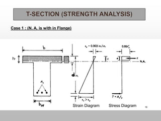
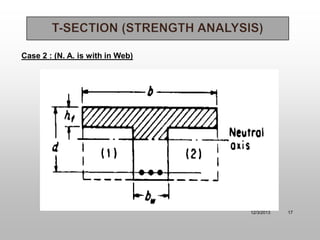
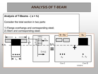
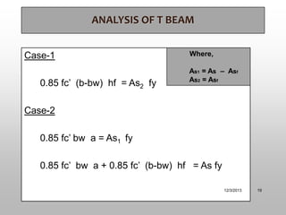
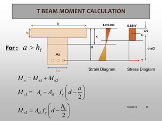


The document discusses T-beam design in the context of civil engineering, focusing on singly and doubly reinforced beams. It outlines the importance of concrete beams being cast integrally with slabs, how they function under different bending moments, and the ACI code guidelines for determining effective flange width. Additionally, it includes analysis methods for T-beams and moment calculation techniques.