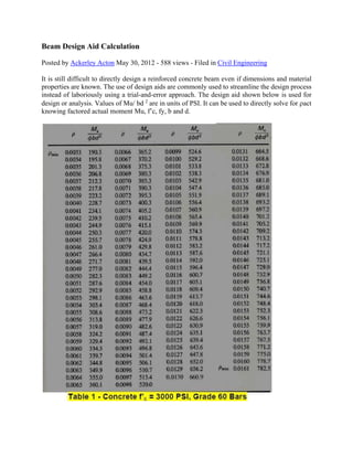
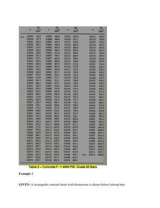
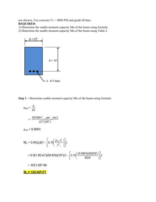
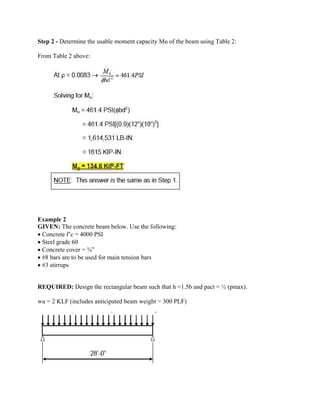
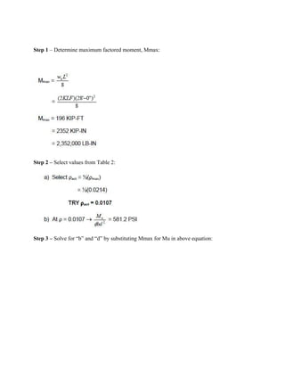
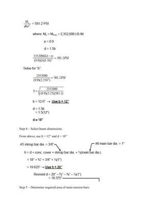
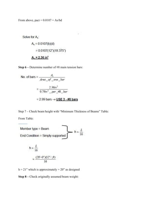
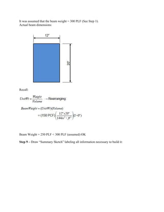
Beam Design Aid Calculation
Posted by Ackerley Acton May 30, 2012 - 588 views - Filed in Civil Engineering
It is still difficult to directly design a reinforced concrete beam even if dimensions and material
properties are known. The use of design aids are commonly used to streamline the design process
instead of laboriously using a trial-and-error approach. The design aid shown below is used for
design or analysis. Values of Mu/ bd 2
are in units of PSI. It can be used to directly solve for act
knowing factored actual moment Mu, f’c, fy, b and d.
Example 1
GIVEN: A rectangular concrete beam with dimensions is shown below (stirrup bars
not shown). Use concrete f’c = 4000 PSI and grade 60 bars.
REQUIRED:
1) Determine the usable moment capacity Mu of the beam using formula.
2) Determine the usable moment capacity Mu of the beam using Table 2.
Step 1 – Determine usable moment capacity Mu of the beam using formula:
Step 2 - Determine the usable moment capacity Mu of the beam using Table 2:
From Table 2 above:
Example 2
GIVEN: The concrete beam below. Use the following:
 Concrete f’c = 4000 PSI
 Steel grade 60
 Concrete cover = ¾”
 #8 bars are to be used for main tension bars
 #3 stirrups
REQUIRED: Design the rectangular beam such that h =1.5b and pact = ½ (pmax).
wu = 2 KLF (includes anticipated beam weight = 300 PLF)
Step 1 – Determine maximum factored moment, Mmax:
Step 2 – Select values from Table 2:
Step 3 – Solve for “b” and “d” by substituting Mmax for Mu in above equation:
Step 4 – Select beam dimensions:
From above, use b = 12” and d = 18”
Step 5 – Determine required area of main tension bars:
From above, pact = 0.0107 = As/bd
Step 6 – Determine number of #8 main tension bars:
Step 7 – Check beam height with “Minimum Thickness of Beams” Table:
From Table:
h = 21” which is approximately = 20” as designed
Step 8 – Check originally assumed beam weight:
It was assumed that the beam weight = 300 PLF (See Step 1).
Actual beam dimensions:
Recall:
Beam Weight = 250 PLF < 300 PLF (assumed) OK
Step 9 – Draw “Summary Sketch” labeling all information necessary to build it:
Source: faculty.delhi.edu
Prepared by: zone4info.com

Beam Design Aid Calculation : As received

  • 1.
    Beam Design AidCalculation Posted by Ackerley Acton May 30, 2012 - 588 views - Filed in Civil Engineering It is still difficult to directly design a reinforced concrete beam even if dimensions and material properties are known. The use of design aids are commonly used to streamline the design process instead of laboriously using a trial-and-error approach. The design aid shown below is used for design or analysis. Values of Mu/ bd 2 are in units of PSI. It can be used to directly solve for act knowing factored actual moment Mu, f’c, fy, b and d.
  • 2.
    Example 1 GIVEN: Arectangular concrete beam with dimensions is shown below (stirrup bars
  • 3.
    not shown). Useconcrete f’c = 4000 PSI and grade 60 bars. REQUIRED: 1) Determine the usable moment capacity Mu of the beam using formula. 2) Determine the usable moment capacity Mu of the beam using Table 2. Step 1 – Determine usable moment capacity Mu of the beam using formula:
  • 4.
    Step 2 -Determine the usable moment capacity Mu of the beam using Table 2: From Table 2 above: Example 2 GIVEN: The concrete beam below. Use the following:  Concrete f’c = 4000 PSI  Steel grade 60  Concrete cover = ¾”  #8 bars are to be used for main tension bars  #3 stirrups REQUIRED: Design the rectangular beam such that h =1.5b and pact = ½ (pmax). wu = 2 KLF (includes anticipated beam weight = 300 PLF)
  • 5.
    Step 1 –Determine maximum factored moment, Mmax: Step 2 – Select values from Table 2: Step 3 – Solve for “b” and “d” by substituting Mmax for Mu in above equation:
  • 6.
    Step 4 –Select beam dimensions: From above, use b = 12” and d = 18” Step 5 – Determine required area of main tension bars:
  • 7.
    From above, pact= 0.0107 = As/bd Step 6 – Determine number of #8 main tension bars: Step 7 – Check beam height with “Minimum Thickness of Beams” Table: From Table: h = 21” which is approximately = 20” as designed Step 8 – Check originally assumed beam weight:
  • 8.
    It was assumedthat the beam weight = 300 PLF (See Step 1). Actual beam dimensions: Recall: Beam Weight = 250 PLF < 300 PLF (assumed) OK Step 9 – Draw “Summary Sketch” labeling all information necessary to build it:
  • 9.