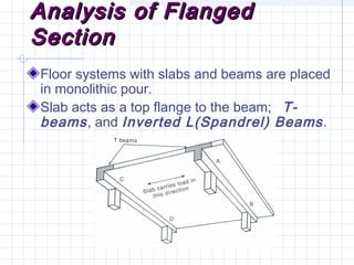
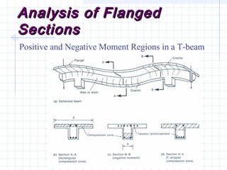
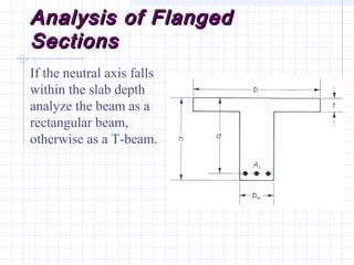
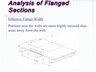
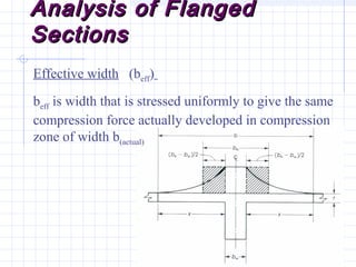
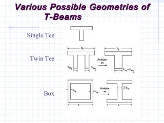
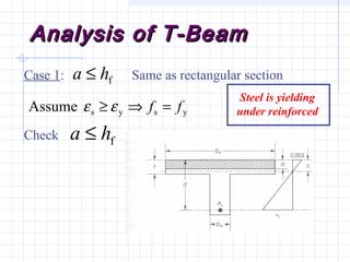
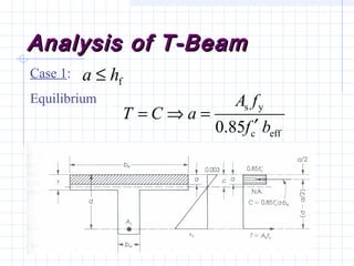
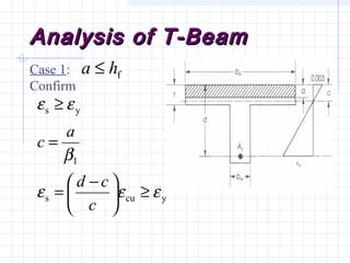
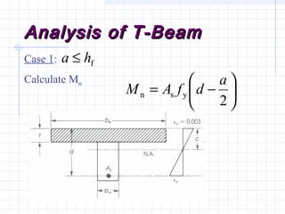
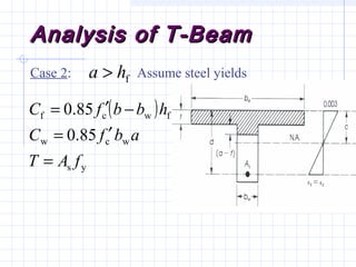
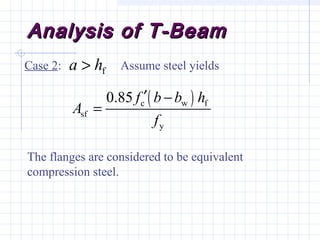
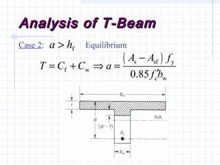
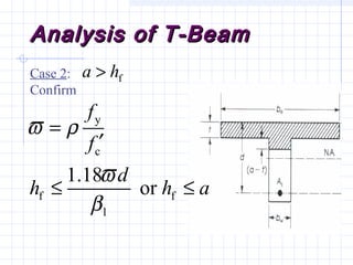
1) The document discusses the analysis of flanged beam sections like T-beams and L-beams. It covers topics like effective flange width, positive and negative moment regions, and ACI code provisions for estimating effective flange width.
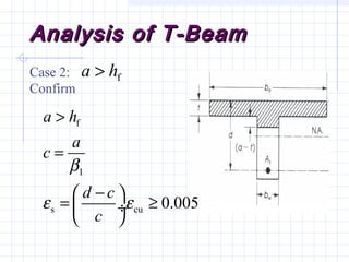
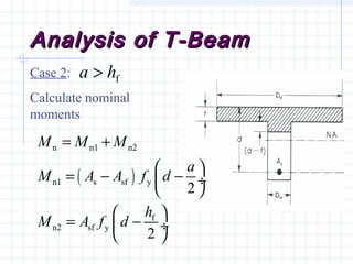
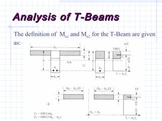
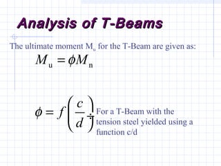
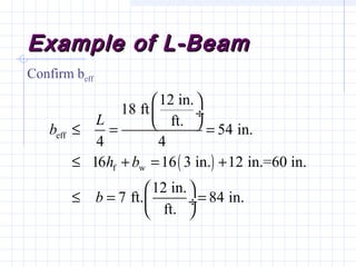
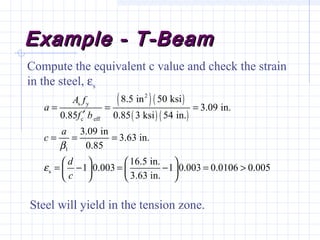
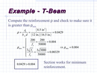
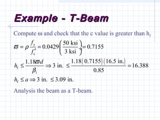
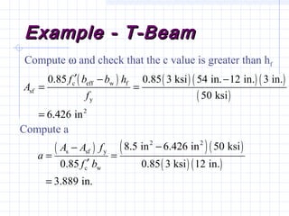
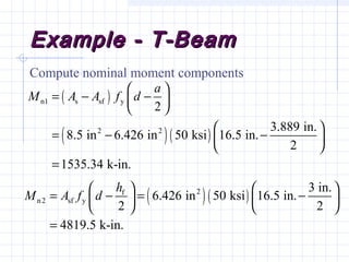
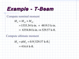
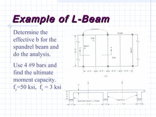
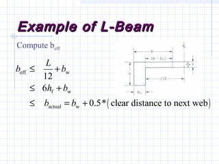
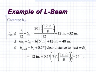
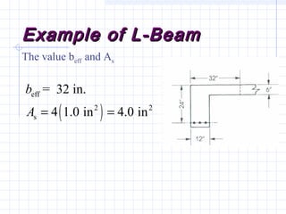
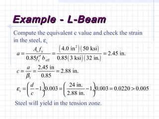
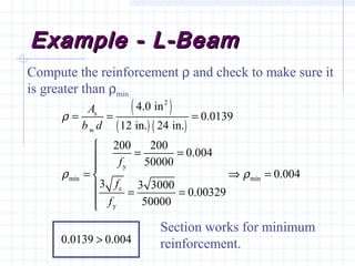
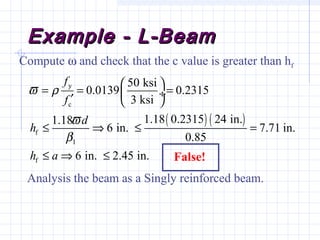
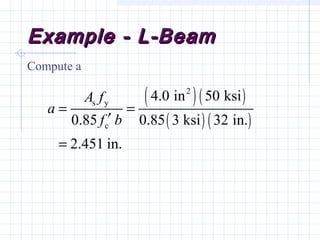
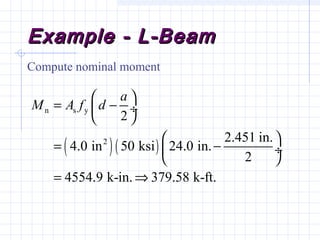
2) Examples are provided for analyzing a T-beam and an L-beam section. This includes calculating the effective flange width, checking steel strain, minimum reinforcement requirements, and computing nominal moments.
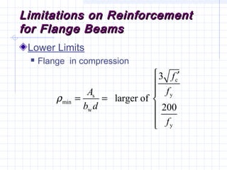
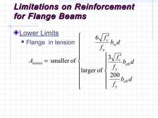
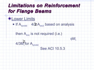
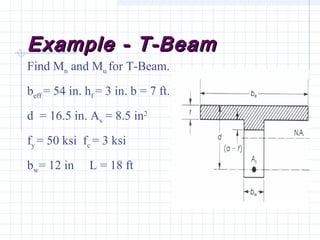
3) Reinforcement limitations for flange beams are also outlined, covering requirements for flanges in compression and tension.
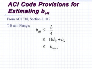
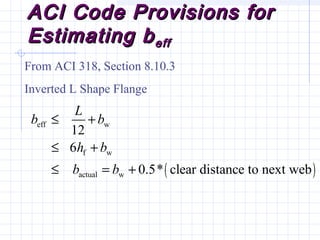
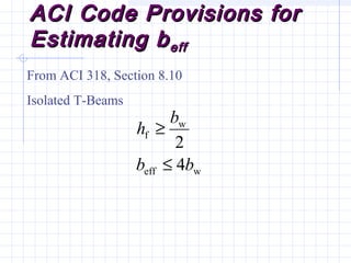


![Doubly reinforced beam]](https://cdn.slidesharecdn.com/ss_thumbnails/doublyreinforcedbeam-190218110616-thumbnail.jpg?width=640&height=640&fit=bounds)


