Downloaded 430 times


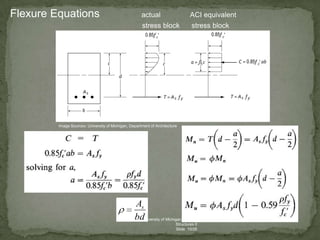
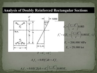
![Relationship b / n the depth `a’ of the equivalent rectangular stress
block & depth `c’ of the N.A. is
a = β1 c
β1= 0.85
; fc’ 4000 psi
β1= 0.85 - 0.05(fc’ – 4000) / 1000
; 4000 < fc’ 8000
β1= 0.65
; fc’> 8000 psi
b
= Asb / bd
= 0.85fc’ ab / (fy. d)
= β1 ( 0.85 fc’ / fy) [ 87,000 / (87,000+fy)]](https://image.slidesharecdn.com/designofrectangularbeam-131201051612-phpapp01/85/Design-of-rectangular-beam-by-USD-11-320.jpg)
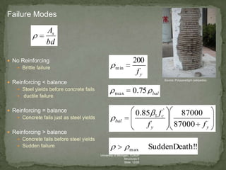
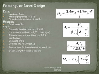
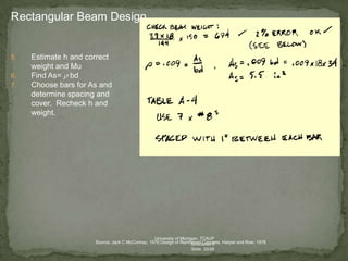

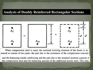
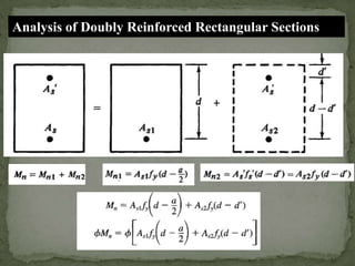
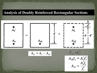
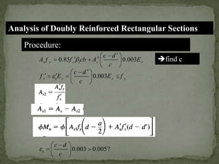


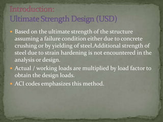
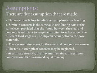
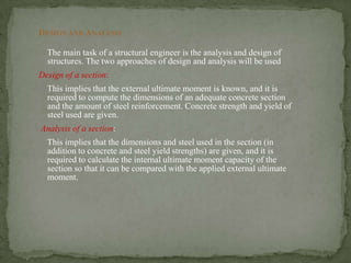
The document discusses the design and analysis of pre-stressed concrete structures, focusing on the ultimate strength concepts for singly and doubly reinforced sections. It outlines the methods for calculating design loads, analyzing internal moments, and determining steel reinforcement requirements based on varying conditions and codes. Important considerations include the stress-strain relationships, failure modes, and specific analytical procedures for rectangular beam designs.


![Doubly reinforced beam]](https://cdn.slidesharecdn.com/ss_thumbnails/doublyreinforcedbeam-190218110616-thumbnail.jpg?width=640&height=640&fit=bounds)