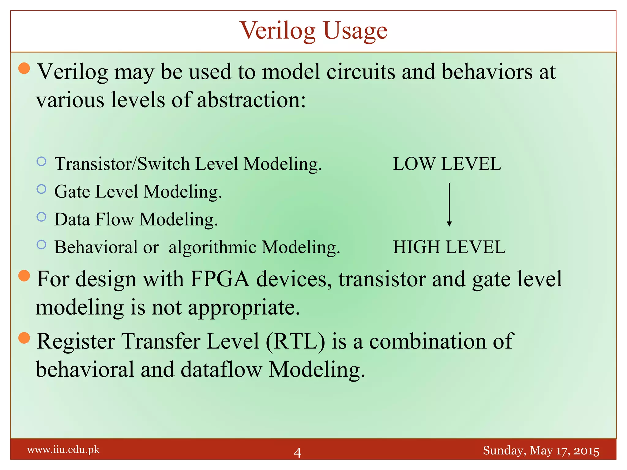
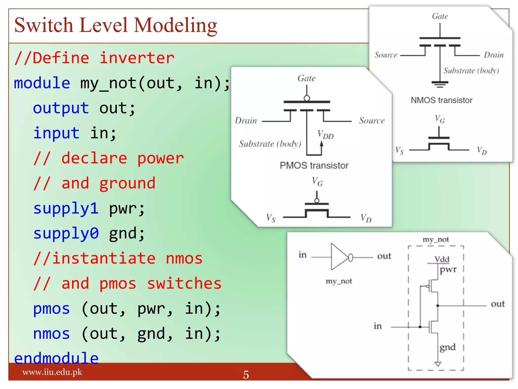
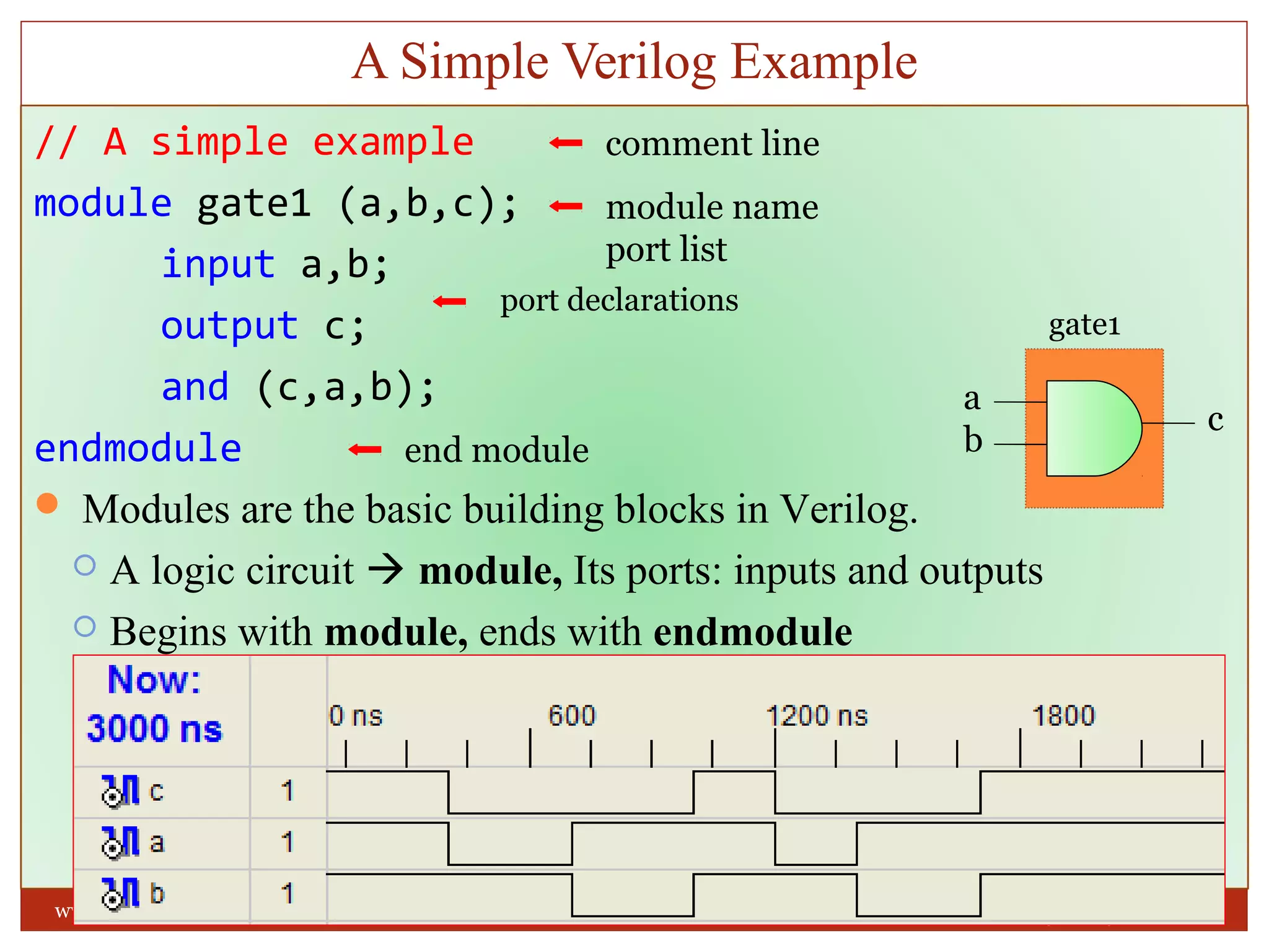
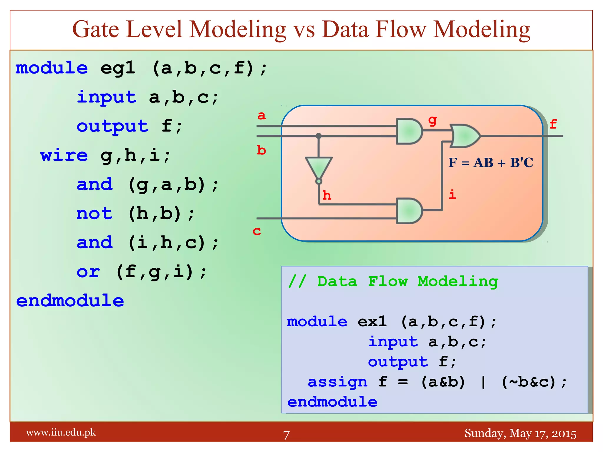
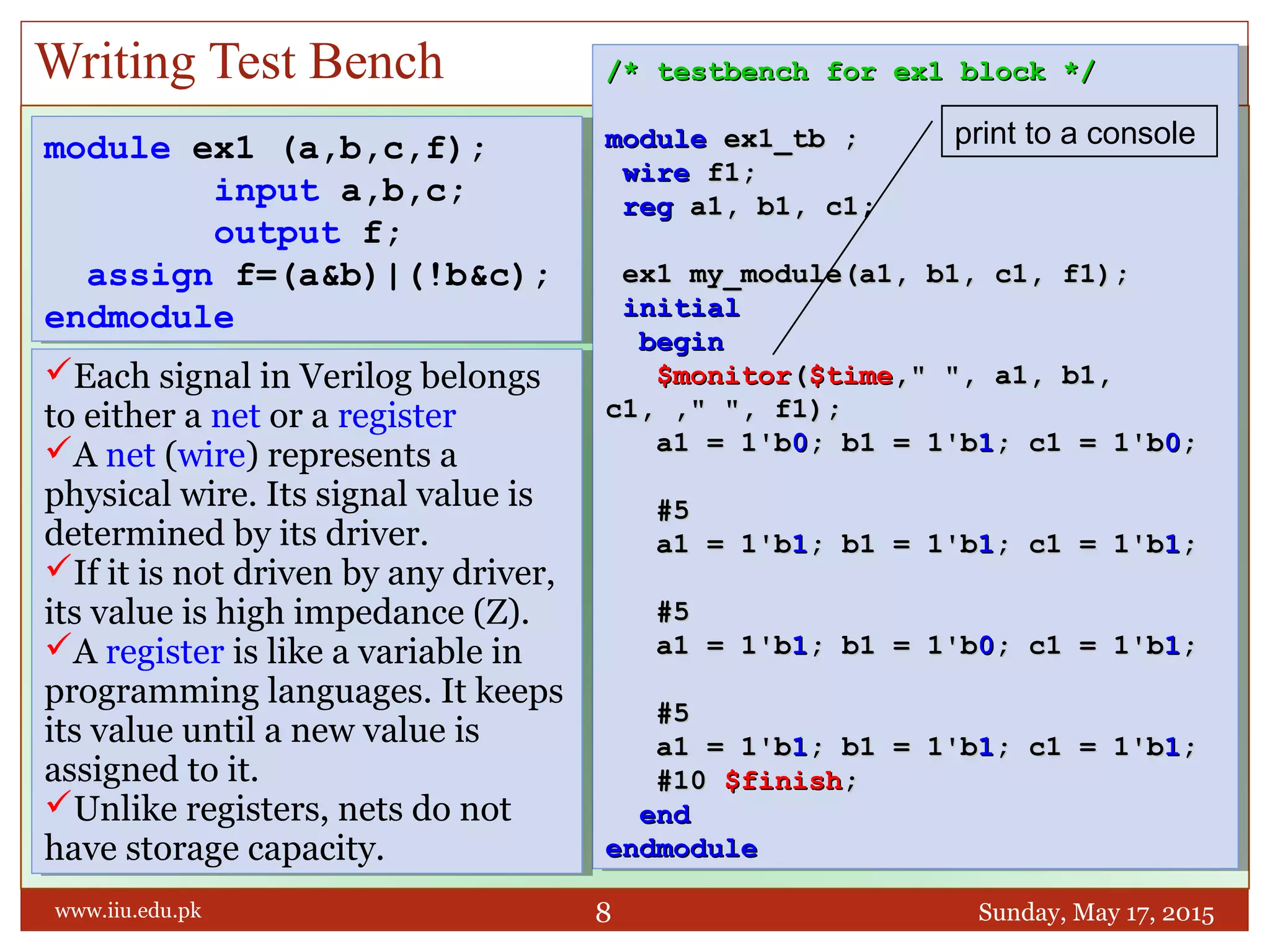
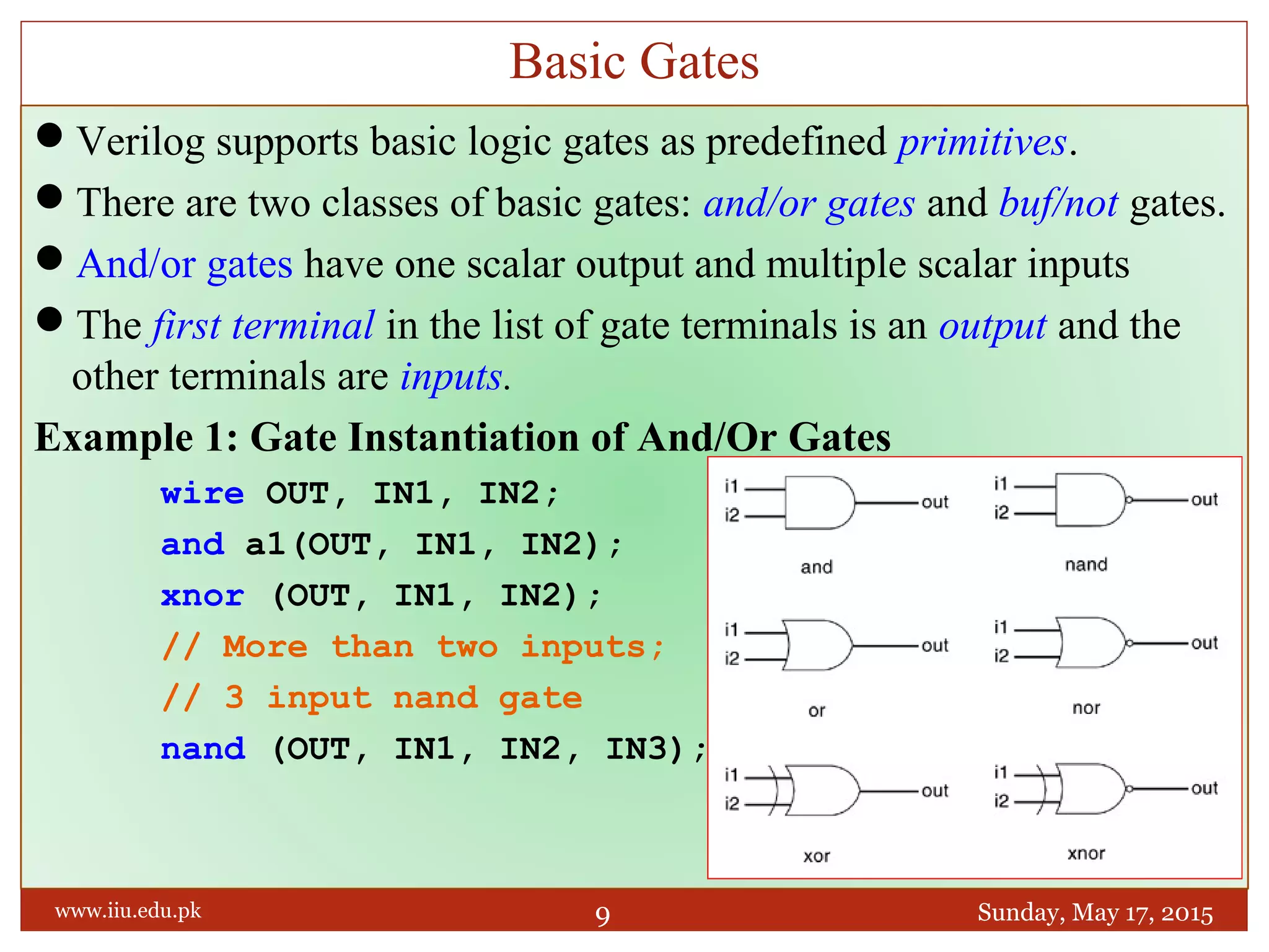
vip Model Basti Call Girls 9999965857 Call or WhatsApp Now Book
Fpga 04-verilog-programming
1. ENGR. RASHID FARID CHISHTI
LECTURER,DEE, FET, IIUI
CHISHTI@IIU.EDU.PK
WEEK 4
VERILOG PROGRAMMING
FPGA Based System Design
Sunday, May 17, 2015
1
www.iiu.edu.pk
2. A hardware description language is a computer language
that is used to describe hardware.
Currently, almost all integrated circuits are designed with
using HDL. Two HDLs are widely used
Verilog HDL
VHDL (Very High Speed Integrated Circuit Hardware
Description Language)
Schematic design entry can be replaced by writing HDL
code that CAD tools understand.
CAD tools can verify the HDL codes, and create the
circuits automatically from HDL codes.
Hardware Description Language
Sunday, May 17, 2015www.iiu.edu.pk 2
3. We use Verilog, not VHDL for FPGA programming
Verilog is more popular in industry than VHDL
They offer similar features
History of Verilog
In 1980s, originally developed by Gateway Design Automation.
In 1990, was put in public domain.
In 1995, adopted as an IEEE standard 1364-1995
In 2001, an enhanced version, Verilog 2001
Functions of Verilog
Design entry, like schematic
Simulation and verification of your design
Synthesis
Facts About Verilog
Sunday, May 17, 2015www.iiu.edu.pk 3
4. Verilog may be used to model circuits and behaviors at
various levels of abstraction:
Transistor/Switch Level Modeling. LOW LEVEL
Gate Level Modeling.
Data Flow Modeling.
Behavioral or algorithmic Modeling. HIGH LEVEL
For design with FPGA devices, transistor and gate level
modeling is not appropriate.
Register Transfer Level (RTL) is a combination of
behavioral and dataflow Modeling.
Verilog Usage
Sunday, May 17, 2015www.iiu.edu.pk 4
6. // A simple example
module gate1 (a,b,c);
input a,b;
output c;
and (c,a,b);
endmodule
Modules are the basic building blocks in Verilog.
A logic circuit module, Its ports: inputs and outputs
Begins with module, ends with endmodule
A Simple Verilog Example
Sunday, May 17, 2015www.iiu.edu.pk 6
comment line
module name
port list
end module
port declarations
a
b
c
gate1
7. module eg1 (a,b,c,f);
input a,b,c;
output f;
wire g,h,i;
and (g,a,b);
not (h,b);
and (i,h,c);
or (f,g,i);
endmodule
Gate Level Modeling vs Data Flow Modeling
Sunday, May 17, 2015www.iiu.edu.pk 7
// Data Flow Modeling
module ex1 (a,b,c,f);
input a,b,c;
output f;
assign f = (a&b) | (~b&c);
endmodule
// Data Flow Modeling
module ex1 (a,b,c,f);
input a,b,c;
output f;
assign f = (a&b) | (~b&c);
endmodule
a
c
F = AB + B'C
b
fg
ih
8. Writing Test Bench
Sunday, May 17, 2015www.iiu.edu.pk 8
/* testbench for ex1 block *//* testbench for ex1 block */
modulemodule ex1_tb ;ex1_tb ;
wirewire f1;f1;
regreg a1, b1, c1;a1, b1, c1;
ex1 my_module(a1, b1, c1, f1);ex1 my_module(a1, b1, c1, f1);
initialinitial
beginbegin
$monitor$monitor(($time$time," ", a1, b1,," ", a1, b1,
c1, ," ", f1);c1, ," ", f1);
a1 = 1'ba1 = 1'b00; b1 = 1'b; b1 = 1'b11; c1 = 1'b; c1 = 1'b00;;
#5#5
a1 = 1'ba1 = 1'b11; b1 = 1'b; b1 = 1'b11; c1 = 1'b; c1 = 1'b11;;
#5#5
a1 = 1'ba1 = 1'b11; b1 = 1'b; b1 = 1'b00; c1 = 1'b; c1 = 1'b11;;
#5#5
a1 = 1'ba1 = 1'b11; b1 = 1'b; b1 = 1'b11; c1 = 1'b; c1 = 1'b11;;
#10#10 $finish$finish;;
endend
endmoduleendmodule
module ex1 (a,b,c,f);
input a,b,c;
output f;
assign f=(a&b)|(!b&c);
endmodule
module ex1 (a,b,c,f);
input a,b,c;
output f;
assign f=(a&b)|(!b&c);
endmodule
Each signal in Verilog belongs
to either a net or a register
A net (wire) represents a
physical wire. Its signal value is
determined by its driver.
If it is not driven by any driver,
its value is high impedance (Z).
A register is like a variable in
programming languages. It keeps
its value until a new value is
assigned to it.
Unlike registers, nets do not
have storage capacity.
print to a console
9. Verilog supports basic logic gates as predefined primitives.
There are two classes of basic gates: and/or gates and buf/not gates.
And/or gates have one scalar output and multiple scalar inputs
The first terminal in the list of gate terminals is an output and the
other terminals are inputs.
Example 1: Gate Instantiation of And/Or Gates
wire OUT, IN1, IN2;
and a1(OUT, IN1, IN2);
xnor (OUT, IN1, IN2);
// More than two inputs;
// 3 input nand gate
nand (OUT, IN1, IN2, IN3);
Basic Gates
Sunday, May 17, 2015www.iiu.edu.pk 9
10. Truth Tables for And/Or Gates
Sunday, May 17, 2015www.iiu.edu.pk 10
and 0 1 x z or 0 1 x z xor 0 1 x z
0 0 0 0 0 0 0 1 x x 0 0 1 x x
1 0 1 x x 1 1 1 1 1 1 1 0 x x
x 0 x x x x x 1 x x x x x x x
z 0 x x x z x 1 x x z x x x x
nand 0 1 x z nor 0 1 x z xnor 0 1 x z
0 1 1 1 1 0 1 0 x x 0 1 0 x x
1 1 0 x x 1 0 0 0 0 1 0 1 x x
x 1 x x x x x 0 x x x x x x x
z 1 x x x z x 0 x x z x x x X
1=True , 0=False, X=Unknown, Z=High impedance
11. Buf/not gates have one scalar input and one or more scalar outputs
The last terminal in the port list is connected to the input. Other
terminals are connected to the outputs
Basic buf/not gate primitives in verilog are buf not
Buf/not gates with additional
control signal are
bufif1, notif1, bufif0, notif0
Buf/Not Gates
Sunday, May 17, 2015www.iiu.edu.pk 11
buf not
input output input output
0 0 0 1
1 1 1 0
x x x x
z x z x
12. The L and H symbols have a
special meaning. The L symbol
means the output has 0 or z value.
The H symbol means the output
has 1 or z value.
Any transition to H or L is treated
as a transition to x.
Examples
//Instantiation of bufif gates.
bufif1 b1 (out, in, ctrl);
bufif0 b0 (out, in, ctrl);
//Instantiation of notif gates
notif1 n1 (out, in, ctrl);
notif0 n0 (out, in, ctrl); x={0,1,z} L={0,z} H={1,z}
bufif1
Ctrl
notif1
Ctrl
0 1 x z
0 1 x z
in
0 z 0 L L
in
0 z 1 H H
1 z 1 H H
1 z 0 L L
x z x x x
x z x x x
z z x x x
z z x x x
bufif0
Ctrl
notif0
Ctrl
0 1 x z 0 1 x z
in
0 0 z L L
in
0 1 z H H
1 1 z H H
1 0 z L L
x x z x x
x x z x x
z x z x x
z x z x x
Truth Table for bufif/notif Gates
Sunday, May 17, 2015www.iiu.edu.pk 12
Editor's Notes
Behavioral or algorithmic level
This is the highest level of abstraction provided by Verilog HDL. A module can be implemented in terms of the desired design algorithm without concern for the hardware implementation details. Designing at this level is very similar to C programming.
Dataflow level
At this level, the module is designed by specifying the data flow. The designer is aware of how data flows between hardware registers and how the data is processed in the design.
Gate level
The module is implemented in terms of logic gates and interconnections between these gates. Design at this level is similar to describing a design in terms of a gate-level logic diagram.
Switch level
This is the lowest level of abstraction provided by Verilog. A module can be implemented in terms of switches, storage nodes, and the interconnections between them. Design at this level requires knowledge of switch-level implementation details.
Verilog allows the designer to mix and match all four levels of abstractions in a design. In the digital design community, the term register transfer level (RTL) is frequently used for a Verilog description that uses a combination of behavioral and dataflow constructs and is acceptable to logic synthesis tools.