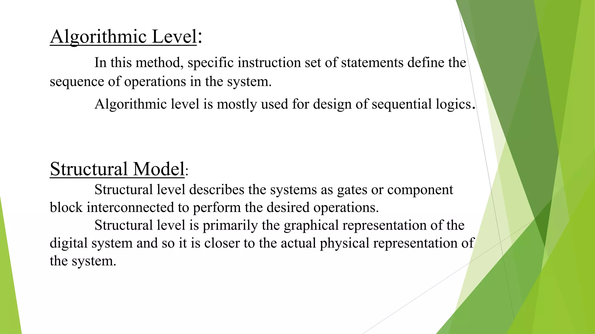
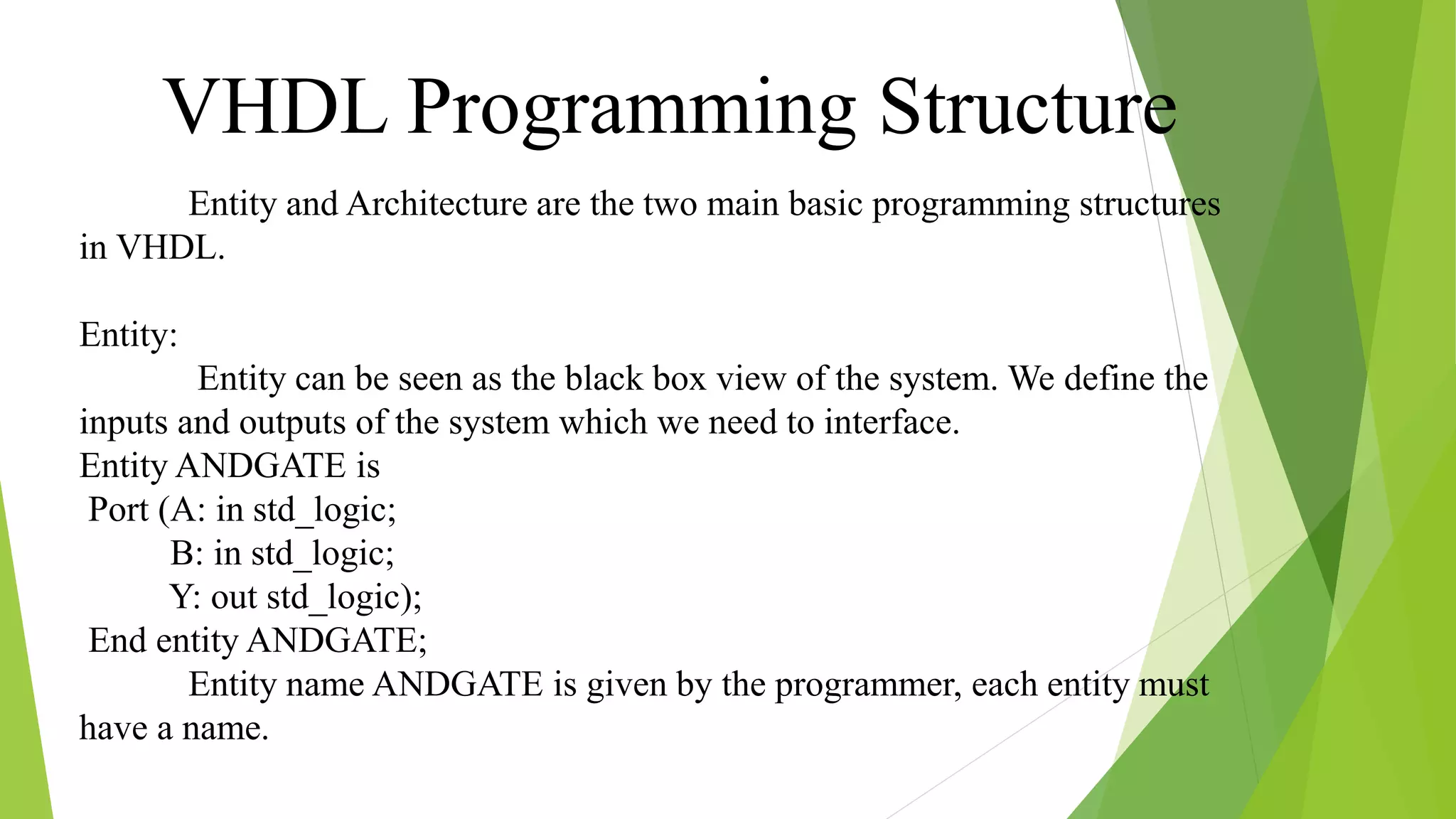
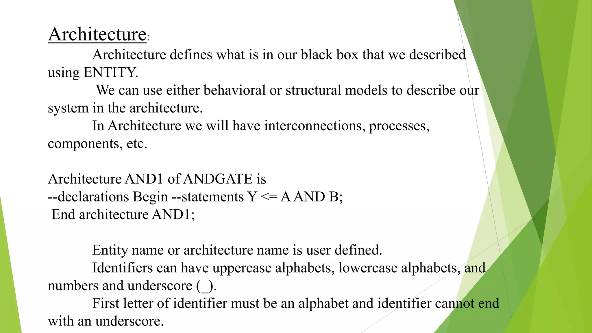
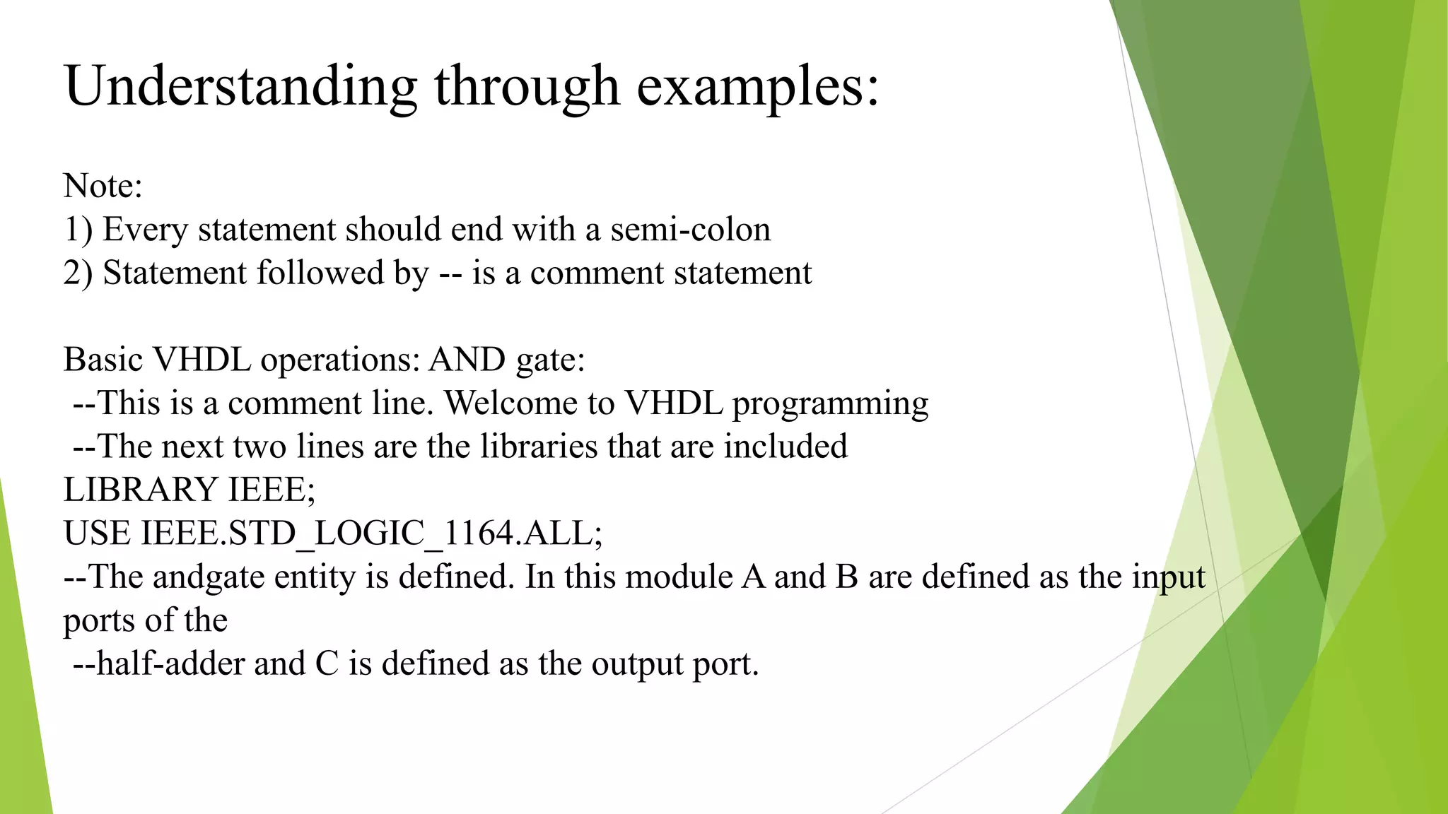
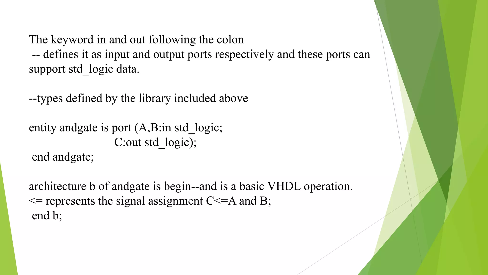
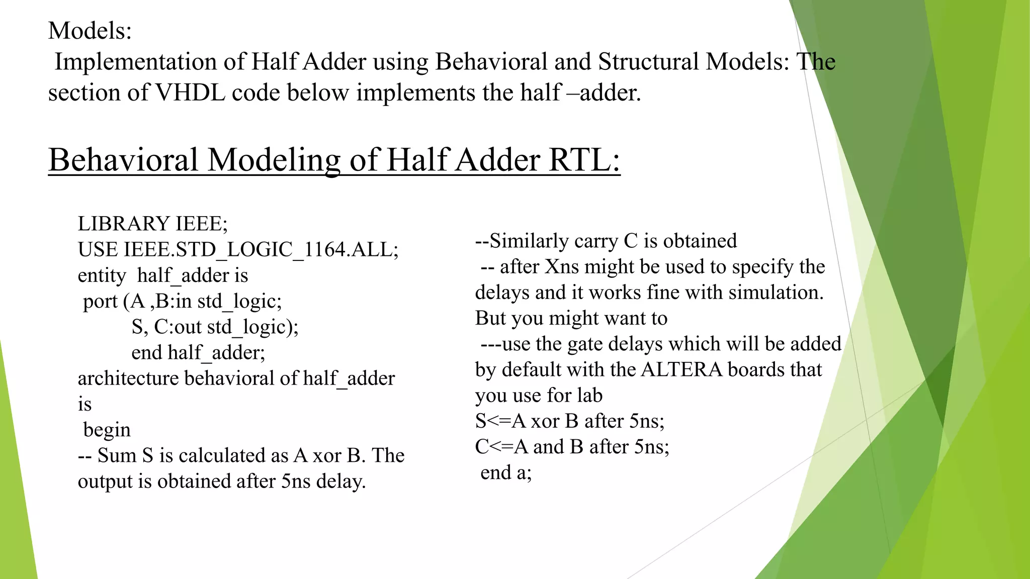
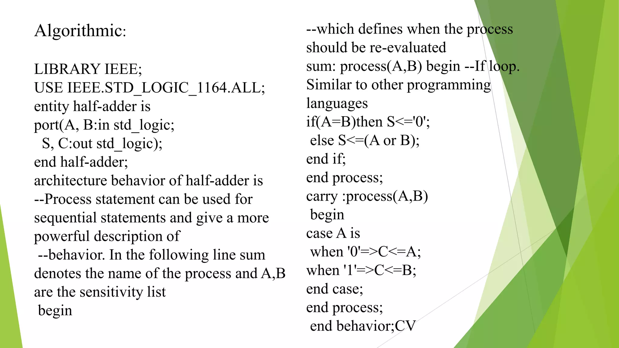
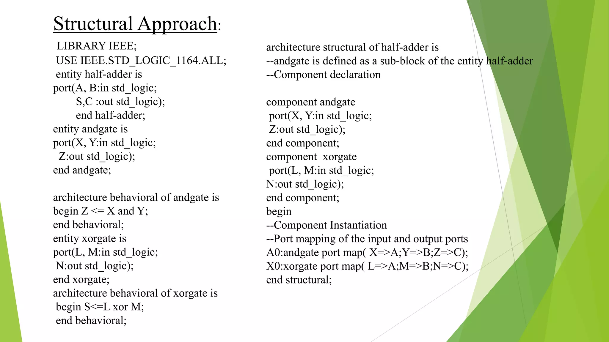
BY:-
YEGATEELA RAJENDRA
13JU1A0440
III YEAR
ELECTRONICS AND
COMMUNICATION DEPT.,
SEMINAR ON
• INTRODUCTION
• TYPES OF
REPRESENTATIONS
• VHDL PROGRAMMING
STRUCTURE
• EXAMPLES
VHDL (Very High Speed IC Hardware description
Language) is one of the standard hardware description language used
to design digital systems.
VHDL can be used to design the lowest level (gate level) of a
digital system to the highest level (VLSI module). VHDL though
being a rigid language with a standard set of rules allows the
designer to use different methods of design giving different
perspectives to the digital system.
Other than VHDL there are many hardware description
languages available in the market for the digital designers such as
Verilog, ABEL, PALASM, CUPL, and etc but VHDL and Verilog are
the most widely used HDLs.
INTRODUCTION
Types of Representation:
VHDL representation can be seen as text file describing a digital
system.
The digital system can be represented in different forms such as a
behavioral model or a structural model.
Most commonly known as levels of abstraction, these levels help
the designer to develop complex systems efficiently.
The major difference between hardware description programming
languages and others is the integration of time. Timing specifications are
used to incorporate propagation delays present in the system.
Behavioral Model:
Behavioral level describes the system the way it behaves instead
of a lower abstraction of its connections.
Behavioral model describes the relationship between the input
and output signals. The description can be a Register Transfer Level
(RTL) or Algorithmic (set of instruction) or simple Boolean equations.
Register Transfer Level:
RTL typically represents data flow within the systems like data
flow between registers.
RTL is mostly used for design of combinational logics.
Structural Model:
Structural level describes the systems as gates or component
block interconnected to perform the desired operations.
Structural level is primarily the graphical representation of the
digital system and so it is closer to the actual physical representation of
the system.
Algorithmic Level:
In this method, specific instruction set of statements define the
sequence of operations in the system.
Algorithmic level is mostly used for design of sequential logics.
Entity and Architecture are the two main basic programming structures
in VHDL.
Entity:
Entity can be seen as the black box view of the system. We define the
inputs and outputs of the system which we need to interface.
Entity ANDGATE is
Port (A: in std_logic;
B: in std_logic;
Y: out std_logic);
End entity ANDGATE;
Entity name ANDGATE is given by the programmer, each entity must
have a name.
VHDL Programming Structure
Architecture:
Architecture defines what is in our black box that we described
using ENTITY.
We can use either behavioral or structural models to describe our
system in the architecture.
In Architecture we will have interconnections, processes,
components, etc.
Architecture AND1 of ANDGATE is
--declarations Begin --statements Y <= AAND B;
End architecture AND1;
Entity name or architecture name is user defined.
Identifiers can have uppercase alphabets, lowercase alphabets, and
numbers and underscore (_).
First letter of identifier must be an alphabet and identifier cannot end
with an underscore.
Understanding through examples:
Note:
1) Every statement should end with a semi-colon
2) Statement followed by -- is a comment statement
Basic VHDL operations: AND gate:
--This is a comment line. Welcome to VHDL programming
--The next two lines are the libraries that are included
LIBRARY IEEE;
USE IEEE.STD_LOGIC_1164.ALL;
--The andgate entity is defined. In this module A and B are defined as the input
ports of the
--half-adder and C is defined as the output port.
The keyword in and out following the colon
-- defines it as input and output ports respectively and these ports can
support std_logic data.
--types defined by the library included above
entity andgate is port (A,B:in std_logic;
C:out std_logic);
end andgate;
architecture b of andgate is begin--and is a basic VHDL operation.
<= represents the signal assignment C<=A and B;
end b;
Models:
Implementation of Half Adder using Behavioral and Structural Models: The
section of VHDL code below implements the half –adder.
Behavioral Modeling of Half Adder RTL:
--Similarly carry C is obtained
-- after Xns might be used to specify the
delays and it works fine with simulation.
But you might want to
---use the gate delays which will be added
by default with the ALTERA boards that
you use for lab
S<=A xor B after 5ns;
C<=A and B after 5ns;
end a;
LIBRARY IEEE;
USE IEEE.STD_LOGIC_1164.ALL;
entity half_adder is
port (A ,B:in std_logic;
S, C:out std_logic);
end half_adder;
architecture behavioral of half_adder
is
begin
-- Sum S is calculated as A xor B. The
output is obtained after 5ns delay.
Algorithmic:
LIBRARY IEEE;
USE IEEE.STD_LOGIC_1164.ALL;
entity half-adder is
port(A, B:in std_logic;
S, C:out std_logic);
end half-adder;
architecture behavior of half-adder is
--Process statement can be used for
sequential statements and give a more
powerful description of
--behavior. In the following line sum
denotes the name of the process and A,B
are the sensitivity list
begin
--which defines when the process
should be re-evaluated
sum: process(A,B) begin --If loop.
Similar to other programming
languages
if(A=B)then S<='0';
else S<=(A or B);
end if;
end process;
carry :process(A,B)
begin
case A is
when '0'=>C<=A;
when '1'=>C<=B;
end case;
end process;
end behavior;CV
Structural Approach:
LIBRARY IEEE;
USE IEEE.STD_LOGIC_1164.ALL;
entity half-adder is
port(A, B:in std_logic;
S,C :out std_logic);
end half-adder;
entity andgate is
port(X, Y:in std_logic;
Z:out std_logic);
end andgate;
architecture behavioral of andgate is
begin Z <= X and Y;
end behavioral;
entity xorgate is
port(L, M:in std_logic;
N:out std_logic);
end xorgate;
architecture behavioral of xorgate is
begin S<=L xor M;
end behavioral;
architecture structural of half-adder is
--andgate is defined as a sub-block of the entity half-adder
--Component declaration
component andgate
port(X, Y:in std_logic;
Z:out std_logic);
end component;
component xorgate
port(L, M:in std_logic;
N:out std_logic);
end component;
begin
--Component Instantiation
--Port mapping of the input and output ports
A0:andgate port map( X=>A;Y=>B;Z=>C);
X0:xorgate port map( L=>A;M=>B;N=>C);
end structural;
vhdl
vhdl

vhdl

  • 2.
  • 3.
    • INTRODUCTION • TYPESOF REPRESENTATIONS • VHDL PROGRAMMING STRUCTURE • EXAMPLES
  • 4.
    VHDL (Very HighSpeed IC Hardware description Language) is one of the standard hardware description language used to design digital systems. VHDL can be used to design the lowest level (gate level) of a digital system to the highest level (VLSI module). VHDL though being a rigid language with a standard set of rules allows the designer to use different methods of design giving different perspectives to the digital system. Other than VHDL there are many hardware description languages available in the market for the digital designers such as Verilog, ABEL, PALASM, CUPL, and etc but VHDL and Verilog are the most widely used HDLs. INTRODUCTION
  • 5.
    Types of Representation: VHDLrepresentation can be seen as text file describing a digital system. The digital system can be represented in different forms such as a behavioral model or a structural model. Most commonly known as levels of abstraction, these levels help the designer to develop complex systems efficiently. The major difference between hardware description programming languages and others is the integration of time. Timing specifications are used to incorporate propagation delays present in the system.
  • 6.
    Behavioral Model: Behavioral leveldescribes the system the way it behaves instead of a lower abstraction of its connections. Behavioral model describes the relationship between the input and output signals. The description can be a Register Transfer Level (RTL) or Algorithmic (set of instruction) or simple Boolean equations. Register Transfer Level: RTL typically represents data flow within the systems like data flow between registers. RTL is mostly used for design of combinational logics.
  • 7.
    Structural Model: Structural leveldescribes the systems as gates or component block interconnected to perform the desired operations. Structural level is primarily the graphical representation of the digital system and so it is closer to the actual physical representation of the system. Algorithmic Level: In this method, specific instruction set of statements define the sequence of operations in the system. Algorithmic level is mostly used for design of sequential logics.
  • 8.
    Entity and Architectureare the two main basic programming structures in VHDL. Entity: Entity can be seen as the black box view of the system. We define the inputs and outputs of the system which we need to interface. Entity ANDGATE is Port (A: in std_logic; B: in std_logic; Y: out std_logic); End entity ANDGATE; Entity name ANDGATE is given by the programmer, each entity must have a name. VHDL Programming Structure
  • 9.
    Architecture: Architecture defines whatis in our black box that we described using ENTITY. We can use either behavioral or structural models to describe our system in the architecture. In Architecture we will have interconnections, processes, components, etc. Architecture AND1 of ANDGATE is --declarations Begin --statements Y <= AAND B; End architecture AND1; Entity name or architecture name is user defined. Identifiers can have uppercase alphabets, lowercase alphabets, and numbers and underscore (_). First letter of identifier must be an alphabet and identifier cannot end with an underscore.
  • 10.
    Understanding through examples: Note: 1)Every statement should end with a semi-colon 2) Statement followed by -- is a comment statement Basic VHDL operations: AND gate: --This is a comment line. Welcome to VHDL programming --The next two lines are the libraries that are included LIBRARY IEEE; USE IEEE.STD_LOGIC_1164.ALL; --The andgate entity is defined. In this module A and B are defined as the input ports of the --half-adder and C is defined as the output port.
  • 11.
    The keyword inand out following the colon -- defines it as input and output ports respectively and these ports can support std_logic data. --types defined by the library included above entity andgate is port (A,B:in std_logic; C:out std_logic); end andgate; architecture b of andgate is begin--and is a basic VHDL operation. <= represents the signal assignment C<=A and B; end b;
  • 12.
    Models: Implementation of HalfAdder using Behavioral and Structural Models: The section of VHDL code below implements the half –adder. Behavioral Modeling of Half Adder RTL: --Similarly carry C is obtained -- after Xns might be used to specify the delays and it works fine with simulation. But you might want to ---use the gate delays which will be added by default with the ALTERA boards that you use for lab S<=A xor B after 5ns; C<=A and B after 5ns; end a; LIBRARY IEEE; USE IEEE.STD_LOGIC_1164.ALL; entity half_adder is port (A ,B:in std_logic; S, C:out std_logic); end half_adder; architecture behavioral of half_adder is begin -- Sum S is calculated as A xor B. The output is obtained after 5ns delay.
  • 13.
    Algorithmic: LIBRARY IEEE; USE IEEE.STD_LOGIC_1164.ALL; entityhalf-adder is port(A, B:in std_logic; S, C:out std_logic); end half-adder; architecture behavior of half-adder is --Process statement can be used for sequential statements and give a more powerful description of --behavior. In the following line sum denotes the name of the process and A,B are the sensitivity list begin --which defines when the process should be re-evaluated sum: process(A,B) begin --If loop. Similar to other programming languages if(A=B)then S<='0'; else S<=(A or B); end if; end process; carry :process(A,B) begin case A is when '0'=>C<=A; when '1'=>C<=B; end case; end process; end behavior;CV
  • 14.
    Structural Approach: LIBRARY IEEE; USEIEEE.STD_LOGIC_1164.ALL; entity half-adder is port(A, B:in std_logic; S,C :out std_logic); end half-adder; entity andgate is port(X, Y:in std_logic; Z:out std_logic); end andgate; architecture behavioral of andgate is begin Z <= X and Y; end behavioral; entity xorgate is port(L, M:in std_logic; N:out std_logic); end xorgate; architecture behavioral of xorgate is begin S<=L xor M; end behavioral; architecture structural of half-adder is --andgate is defined as a sub-block of the entity half-adder --Component declaration component andgate port(X, Y:in std_logic; Z:out std_logic); end component; component xorgate port(L, M:in std_logic; N:out std_logic); end component; begin --Component Instantiation --Port mapping of the input and output ports A0:andgate port map( X=>A;Y=>B;Z=>C); X0:xorgate port map( L=>A;M=>B;N=>C); end structural;