Download to read offline


![Memory Operation
reg [31:0] register_file [0:7];
wire [31:0] rf_bus;
wire r2b4;
assign rf_bus = register_file [2];
assign r2b4 = rf_bus[4];
Can’t use register_file[2][4] for assigning value to
variable r2b4](https://image.slidesharecdn.com/verilogtutorial-201201073833/85/Verilog-tutorial-28-320.jpg)

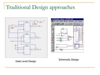
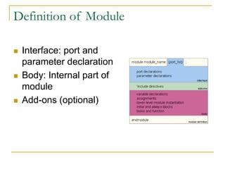
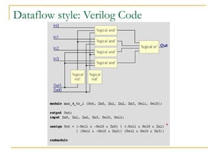
This document discusses Verilog HDL as a solution for designing digital circuits. It provides an overview of traditional design approaches like gate-level and schematic design and their limitations for large, complex designs. Verilog HDL was developed in the 1980s to provide a simple, intuitive way to describe digital circuits for modeling, simulation, and analysis. It allows a top-down design approach with modules that have well-defined interfaces and behaviors. The document covers various coding styles in Verilog like structural, dataflow, and behavioral, as well as concepts like ports, parameters, nets, registers, delays, and test benches. It provides examples of memory operations and emphasizes thinking concurrently when writing Verilog code.