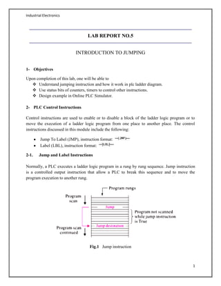
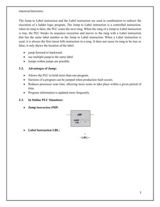
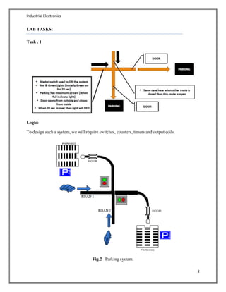
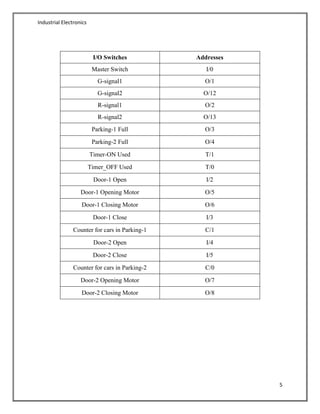
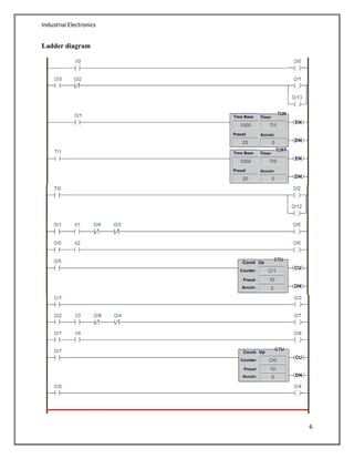
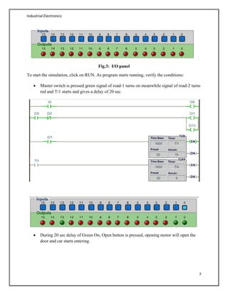
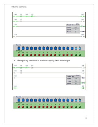
Industrial Electronics
1
LAB REPORT NO.5
INTRODUCTION TO JUMPING
1- Objectives
Upon completion of this lab, one will be able to
 Understand jumping instruction and how it work in plc ladder diagram.
 Use status bits of counters, timers to control other instructions.
 Design example in Online PLC Simulator.
2- PLC Control Instructions
Control instructions are used to enable or to disable a block of the ladder logic program or to
move the execution of a ladder logic program from one place to another place. The control
instructions discussed in this module include the following:
Jump To Label (JMP), instruction format:
Label (LBL), instruction format:
2-1. Jump and Label Instructions
Normally, a PLC executes a ladder logic program in a rung by rung sequence. Jump instruction
is a controlled output instruction that allow a PLC to break this sequence and to move the
program execution to another rung.
Fig.1 Jump instruction
Industrial Electronics
2
The Jump to Label instruction and the Label instruction are used in combination to redirect the
execution of a ladder logic program. The Jump to Label instruction is a controlled instruction;
when its rung is false, the PLC scans the next rung. When the rung of a Jump to Label instruction
is true, the PLC breaks its sequence execution and moves to the rung with a Label instruction
that has the same label number as the Jump to Label instruction. When a Label instruction is
used, it is always the first (most left) instruction in a rung. It does not cause its rung to be true or
false; it only shows the location of the label.
jump forward or backward.
use multiple jump to the same label.
Jumps within jumps are possible.
2-2. Advantages of Jump:
Allows the PLC to hold more than one program.
Sections of a program can be jumped when production fault occurs.
Reduces processor scan time, allowing more scans to take place within a given period of
time.
Program information is updated more frequently.
2-3. In Online PLC Simulator:
Jump Instruction JMP:
Label Instruction LBL:
Industrial Electronics
3
LAB TASKS:
Task . 1
Logic:
To design such a system, we will require switches, counters, timers and output coils.
Fig.2 Parking system.
Industrial Electronics
4
Ladder logic allows this function to be represented this way. Fig.2 shows the actual way in which
the process takes place.
Explanation:
To implement this using ladder logic, we needed NO and NC contacts, timer on-delay instruction
TON, timer off-delay instruction TOFF, UP counters CTU and output coils.
Press the master switch and control system will start operating.
Initially green signal of road-1 is ON and remain ON for 20 seconds, meanwhile the
road-2 has red signal.
After 20sec, road-1 green signal turns off, and red signal gets ON, at the same time road-
2 red signal turns off, and green signal turns ON.
When the green led of any of road gets on, pressing the "Door-1 Open ", car will enter
into parking and the counter value is incremented on the entry of each new car.
After entering the park, pressing the "Door-1 Close” from inside will close the door.
When the parking capacity is maximum i.e. 10, "Parking-1 Full" light will turn on.
Now no more cars will enter the parking lot, and the door will not open for any new car.
Similarly for Parking-2, above 4 steps will repeat.
Setting the timer:
Set Accumulator value equal to zero. Find the preset value and time base value for given time-
delay. If and
Setting the counters:
Set Accumulator value equal to zero. Also set the preset value required.
If and
Simulation:
Login plcsimulator.net and form the ladder logic as:
Addressing the components
Industrial Electronics
5
I/O Switches Addresses
Master Switch I/0
G-signal1 O/1
G-signal2 O/12
R-signal1 O/2
R-signal2 O/13
Parking-1 Full O/3
Parking-2 Full O/4
Timer-ON Used T/1
Timer_OFF Used T/0
Door-1 Open I/2
Door-1 Opening Motor O/5
Door-1 Closing Motor O/6
Door-1 Close I/3
Counter for cars in Parking-1 C/1
Door-2 Open I/4
Door-2 Close I/5
Counter for cars in Parking-2 C/0
Door-2 Opening Motor O/7
Door-2 Closing Motor O/8
Industrial Electronics
6
Ladder diagram
Industrial Electronics
7
Fig.3: I/O panel
To start the simulation, click on RUN. As program starts running, verify the conditions:
Master switch is pressed green signal of road-1 turns on meanwhile signal of road-2 turns
red and T/1 starts and gives a delay of 20 sec.
During 20 sec delay of Green On, Open button is pressed, opening motor will open the
door and car starts entering.
Industrial Electronics
8
When parking lot reaches its maximum capacity, Door will not open.
Industrial Electronics
9
Conclusion:
Desired system is achieved.
Above simulation & ladder diagram show the logic is correct.

Parking Control System using PLC

  • 1.
    Industrial Electronics 1 LAB REPORTNO.5 INTRODUCTION TO JUMPING 1- Objectives Upon completion of this lab, one will be able to  Understand jumping instruction and how it work in plc ladder diagram.  Use status bits of counters, timers to control other instructions.  Design example in Online PLC Simulator. 2- PLC Control Instructions Control instructions are used to enable or to disable a block of the ladder logic program or to move the execution of a ladder logic program from one place to another place. The control instructions discussed in this module include the following: Jump To Label (JMP), instruction format: Label (LBL), instruction format: 2-1. Jump and Label Instructions Normally, a PLC executes a ladder logic program in a rung by rung sequence. Jump instruction is a controlled output instruction that allow a PLC to break this sequence and to move the program execution to another rung. Fig.1 Jump instruction
  • 2.
    Industrial Electronics 2 The Jumpto Label instruction and the Label instruction are used in combination to redirect the execution of a ladder logic program. The Jump to Label instruction is a controlled instruction; when its rung is false, the PLC scans the next rung. When the rung of a Jump to Label instruction is true, the PLC breaks its sequence execution and moves to the rung with a Label instruction that has the same label number as the Jump to Label instruction. When a Label instruction is used, it is always the first (most left) instruction in a rung. It does not cause its rung to be true or false; it only shows the location of the label. jump forward or backward. use multiple jump to the same label. Jumps within jumps are possible. 2-2. Advantages of Jump: Allows the PLC to hold more than one program. Sections of a program can be jumped when production fault occurs. Reduces processor scan time, allowing more scans to take place within a given period of time. Program information is updated more frequently. 2-3. In Online PLC Simulator: Jump Instruction JMP: Label Instruction LBL:
  • 3.
    Industrial Electronics 3 LAB TASKS: Task. 1 Logic: To design such a system, we will require switches, counters, timers and output coils. Fig.2 Parking system.
  • 4.
    Industrial Electronics 4 Ladder logicallows this function to be represented this way. Fig.2 shows the actual way in which the process takes place. Explanation: To implement this using ladder logic, we needed NO and NC contacts, timer on-delay instruction TON, timer off-delay instruction TOFF, UP counters CTU and output coils. Press the master switch and control system will start operating. Initially green signal of road-1 is ON and remain ON for 20 seconds, meanwhile the road-2 has red signal. After 20sec, road-1 green signal turns off, and red signal gets ON, at the same time road- 2 red signal turns off, and green signal turns ON. When the green led of any of road gets on, pressing the "Door-1 Open ", car will enter into parking and the counter value is incremented on the entry of each new car. After entering the park, pressing the "Door-1 Close” from inside will close the door. When the parking capacity is maximum i.e. 10, "Parking-1 Full" light will turn on. Now no more cars will enter the parking lot, and the door will not open for any new car. Similarly for Parking-2, above 4 steps will repeat. Setting the timer: Set Accumulator value equal to zero. Find the preset value and time base value for given time- delay. If and Setting the counters: Set Accumulator value equal to zero. Also set the preset value required. If and Simulation: Login plcsimulator.net and form the ladder logic as: Addressing the components
  • 5.
    Industrial Electronics 5 I/O SwitchesAddresses Master Switch I/0 G-signal1 O/1 G-signal2 O/12 R-signal1 O/2 R-signal2 O/13 Parking-1 Full O/3 Parking-2 Full O/4 Timer-ON Used T/1 Timer_OFF Used T/0 Door-1 Open I/2 Door-1 Opening Motor O/5 Door-1 Closing Motor O/6 Door-1 Close I/3 Counter for cars in Parking-1 C/1 Door-2 Open I/4 Door-2 Close I/5 Counter for cars in Parking-2 C/0 Door-2 Opening Motor O/7 Door-2 Closing Motor O/8
  • 6.
  • 7.
    Industrial Electronics 7 Fig.3: I/Opanel To start the simulation, click on RUN. As program starts running, verify the conditions: Master switch is pressed green signal of road-1 turns on meanwhile signal of road-2 turns red and T/1 starts and gives a delay of 20 sec. During 20 sec delay of Green On, Open button is pressed, opening motor will open the door and car starts entering.
  • 8.
    Industrial Electronics 8 When parkinglot reaches its maximum capacity, Door will not open.
  • 9.
    Industrial Electronics 9 Conclusion: Desired systemis achieved. Above simulation & ladder diagram show the logic is correct.