The document provides information about PLC ladder programming including:
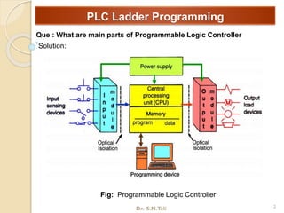
- The main parts of a PLC and advantages of PLCs such as flexibility and cost effectiveness.
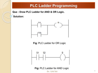
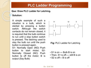
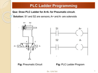
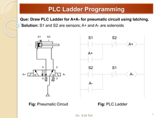
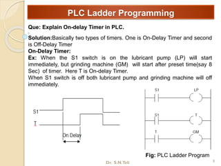
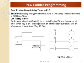
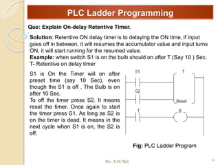
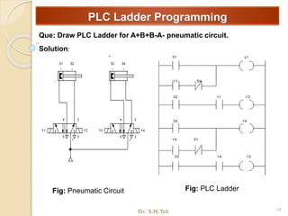
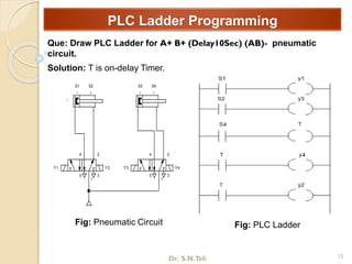
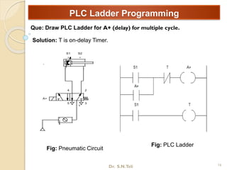
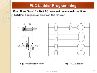
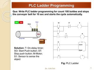
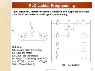
- Examples of PLC ladder logic for AND/OR logic, latching, timers, counters, and pneumatic circuits.
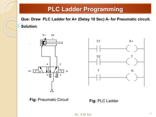
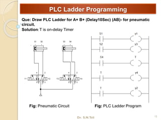
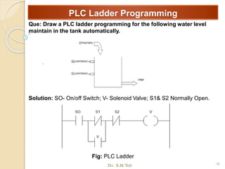
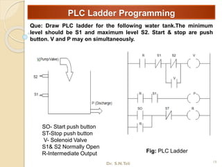
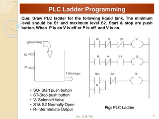
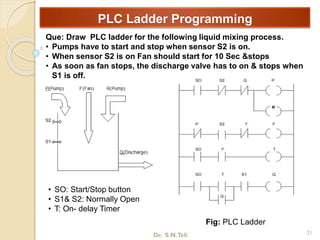
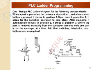
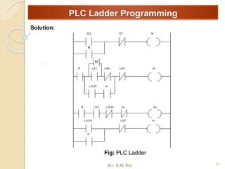
- Solutions to questions about drawing PLC ladders for different pneumatic circuits, water level controls, mixing processes, and conveyor operations using components like sensors, solenoid valves, and timers.