Download to read offline
![International Research Journal of Engineering and Technology (IRJET) e-ISSN: 2395-0056
Volume: 09 Issue: 05 | May 2022 www.irjet.net p-ISSN: 2395-0072
© 2022, IRJET | Impact Factor value: 7.529 | ISO 9001:2008 Certified Journal | Page 3414
CONCLUSION
In today's developed world elevators are becoming
increasingly important through the development of
architectural technology. The design of the cash-based
control system is very important as it is veryimportanttodo
all the work. Staircase layout is preferred as it is easy to plan
different PLCs. Before embarkingonthisprojectithasbeena
challenge for us to develop a proper step ladder approachas
we started in the PLC planning field. Graduallyweareableto
design a ladder by adapting to different types of PLC
systems. By splitting all the interfacing modules into
separate sections we also successfully completed.
REFERENCES
[1] Xialoling Yang, Qunxiong Zhu, Hong Xu,, “Design and
practice of an elevator control system based on PLC”, In
proceedings of IEEE workshop on Power Electronics and
Intelligent Transportation System, pp. 94 - 99 2008.
[2] Dae-Woongchung, Hyung-Min Ryu, Young-Min Lee,
“Drive systems for high-speed gearless elevators”, IEEE
industry Applications Magazine, vol. 7, pp 52-56, 2001
[3] Darshil, Sagar, Rajiv, Pangaokar, S.A. Sharma,
“Development of a PLC Based Elevator System with Colour
Sensing Capabilities for Material Handling in Industrial
Plant”, In proceedings of IEEE Joint International conference
on Power System Technology, pp 1-7, 2008
[4] Eunson jung, HyunjaeYoo, Seung-ki Sul, Hong- soon Choi
and Yun-Young Choi, “ A Nine-Phase choi and Yun-Young
Choi, an Ultrahigh-speed Elevator”, IEEE Transactions on
Industry Application, vol.48, pp 987-995.
[5] Peng Wang, “ A Control System Design for Hand Elevator
Based on PLC”, In proceedings of IEEE Conference
Publications, vol.1, pp 77-74, 2012
BIOGRAPHIES
Mr. Maduguri Sudhir, (M.Tech. with
specialization in Digital Electrinics and
Communication System ), He have special
interest on Digital Image Processing and
Ladder Programming. He has 12 years of
experience in academics. Presently he is
working as Assistant Professor in KITS Engineering College,
Guntur, AP.
Ms.Bathini Koteswari is a UG Student of
Electronics and Communication Engineering,
JNTUK, Kakinada, AP. She is very interested in
Micro controllers and Aurdino coding
Ms. Devarapalli Sony is a UG Student of
Electronics and Communication Engineering,
JNTUK, Kakinada, AP. She is very interested in
automation systems.
Ms.Chinthaguntla Naveena is a UG Studentof
Electronics and Communication Engineering,
JNTUK, Kakinada, AP. She is very interested in
AI systems.
Ms. Illa Siva Naga Chaitanya is a UG Student
of Electronics and Communication
Engineering, JNTUK, Kakinada, AP. Sheisvery
interested in automation systems.
systems.](https://image.slidesharecdn.com/irjet-v9i5691-221006065221-27fb5be2/85/A-Mechatronics-Approach-For-Concerting-the-Programmable-Logic-Controller-With-Ladder-Programming-To-Regulate-The-Elevator-6-320.jpg)

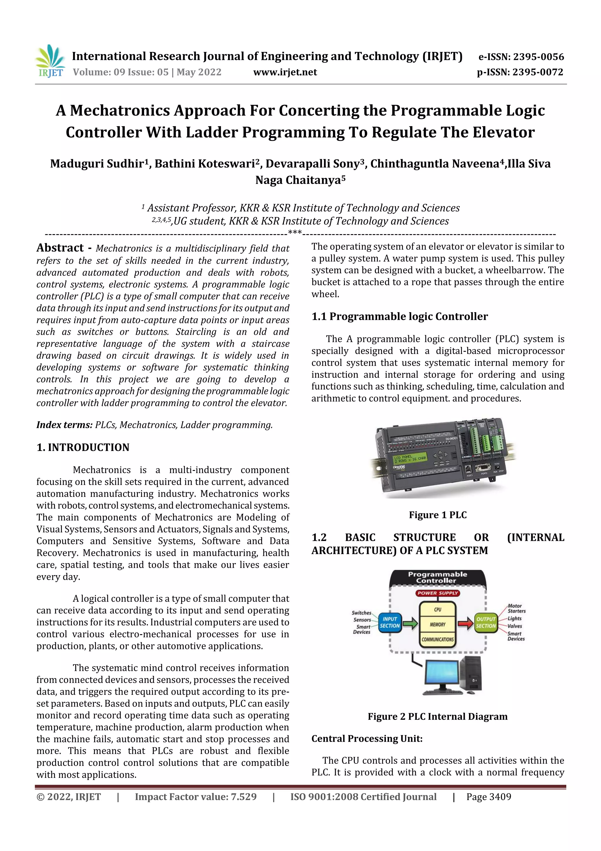
This document describes a mechatronics approach to designing a programmable logic controller (PLC) using ladder programming to control an elevator system. It discusses using a PLC to receive input signals and send output instructions to control the elevator's electro-mechanical processes. The document outlines the proposed method which includes selecting inputs and outputs, and developing ladder programming for push buttons, door opening/closing sensors, up/down motors, fan, light, speaker, and number display. Diagrams of the ladder programs and the elevator system are provided. The advantages of using a PLC-based control system to regulate the elevator are that it can reduce size, costs and simplify control compared to traditional relay-based systems.