SlideShare a Scribd company logo
1 of 33
How Do You Use PID on a PLC?
There are a number of hidden variables that the PLC programmer must
understand before adding the command into a line of ladder logic. The overall
concept is the same across brands, with many similarities, but a few examples
will be shown later to illustrate how this might look to the end user.
Figure 1. A common feedback device for closed-loop systems is the temperature sensor. Other
examples include pressure and position. Image used courtesy of Adobe Stock
First, we must define three critical pieces of information that the PID command
MUST understand.
The Process Variable or PV is the input address or the tag variable that
contains the analog input information from the sensor. This may be the raw
data from the input, perhaps between 0-65535 (for a 16-bit input) or less,
depending on the PLC and module resolution. It may also be scaled literal
values from a real-world sensor, perhaps the value being used is -100 to -50
for a temperature range, or maybe 0-350 for the mm stroke of an actuator.
The reason this data must be understood is that the PID command is likely to
expect min/max limits from the programmer, if the input PV goes above or
below these limits, the program will stop executing and send a fault, indicating
a system error. These input limits are sometimes optional.
Likewise, the scale of data for the Output must also be understood. If the
signal is directly attached to an analog output address for a proportional
valve, the output min/max should relate to the resolution of the analog
output, maybe the same 0-65535 range, or maybe rather in the -32,768 to
32,767 range if the output is capable of negative voltage outputs.
Figure 2. An example of an output device might include a servo-controlled proportional valve
for precise hydraulic motion. Image used courtesy of Continental Hydraulics
PID Scaling Values
Many PLCs differentiate the concepts of a min/max used for scaling versus a
min/max limit. While the scaling is used only to compute a linear slope (x
input equals y output), this will NOT force an upper or lower limit on the
output, it simply means that ‘minimum input equals minimum output, and
maximum input equals maximum output’. An extrapolation factor.
PID Limit Values
A limit, on the other hand, is not used in the computation but is rather used to
set alarms and boundaries. If the input goes above or below a limit, the
system itself is out of control and may experience damage. If the output goes
above or below a limit, the valve or servo may experience harsh stress and
damage the final load element.
Back to the output variable; the output must be defined with both scale and
limit min/max values. If the limit min/max values are set by default, they
cannot both be zero, otherwise, the output will always be equal to zero, and
the system will appear to be unresponsive. For temperature and flow control
processes, the output is often expressed as a percentage, from 0% to 100%,
relating to the 0-10v or the 4-20 mA signal to the proportional valve or PWM
output.
The last of the three critical PID data values (but far from least important) is
the Set Point or SP. This value must have the same unit structure as the PV.
That means that if the PV is measured in temp degrees, or in mm, or in raw
data, then the SP must likewise be defined. The error is the difference
(subtraction) between the two data values, so you must have the same units–
you can’t subtract 70 degrees from 35,682, that just doesn’t make sense. That
difference may be positive or negative, that is an important detail!
Example using a Modern PLC System
What if we examine an actual example of PID implementation to learn which
control values are shown by the command, as well as which items must be
considered behind the scenes for proper operation?
Let me begin by saying I cannot possibly explain all elements of the tags
involved with each PID command and keep the scope to one article. And
indeed, if you really need to implement PID for your process, you need to read
far more than just this article. However, explaining the basic I/O data and the
controlling factors can be a real aid in understanding how to establish the
command.
PID Command in Rockwell’s Studio 5000
Allen-Bradley ControlLogix and CompactLogix
When you drag a PID function block onto a ladder rung, the function will
execute as long as the rung is true according to a regularly updated timer. If
you wish to have control over the time delay for PID updates, the tag is
PID_Name.UPT with a base of milliseconds.
PID_Name is whatever name you assign to the PID type tag created in your
controller or program scope tag listing.
Figure 3. PID command in Studio 5000.
In my case, I have created PID_1 with fictitious tags called ‘analog input’ and
‘analog output’ to represent the PV and output (CV). If you have a real analog
I/O module, simply use the analog values from these modules. Both of these
tags are REAL data types.
I set the PID function to update every 10 ms (meaning that the PID_1.UPT tag
= 0.01).
The scaling values are determined by default when the function is downloaded
to the controller, but you can adjust the tags or open the tuning/configuration
menu by clicking the three dots in the upper-right corner of the PID function
block.
To observe the change in this PID function, you can adjust either the SP or the
PV to simulate a real-world situation.
As you can see from this example, the SP is 80, the PV is so close that the SP
that the output is reduced to a very tiny percentage. Note: I excluded Ki
(integral gain) from this loop to stabilize the output for getting a screenshot,
so the PV will never actually reach the SP exactly.
How Does the Scaling Affect the Output?
For a simulated scenario, you can adjust the scale of the output and input
however you wish, since it’s not connected to an actual responsive device. But
remember this: if you link the Control Variable to a real analog output, you
must establish a max and min scale that will send the proper value to the
analog output tag.
For example, if you are using a ControlLogix 1756-OF4, with 4x voltage
outputs, the resolution is 15 bits over 0-10 volts. This means that your
minimum scale should be 0, and the max scale should be 32,767 (2^15-1).
Alternatively, if you are using the current output on this module for a 0-20 mA
output, this is rated for 16 bits. So, in this case, the min scale output should be
-32,768 (-2^15) while the max scale output remains at 32,767 (2^15-1).
These details for this specific module come from pages 183-184 of the user
manual. Please do not rely on these numbers for all situations.
Most output modules can adapt to devices with 0-10 volt, 0-5 volt, -10 to 10
volt, -20 mA, and 4-20 mA just with some configuration and wiring details, so
make sure your output scale matches the type of signal you wish to send.
Although it may be impossible to provide an entire scope of coverage for PID
controls and programming in one article, it can be helpful to understand the
basic functions, then learn how to set them up in a simulated environment to
be sure they will respond as accurately as possible to minimize the chance of
downtime and failures when the real system is created.
Connecting Multiple PLCs to an
HMI
Learn the basics of connecting multiple PLCs to an
HMI using various data types.
Most entry-level training for control systems includes programmable logic
controllers (PLCs)—ladder programming, wiring inputs and outputs, as well as
tag databases and the various data types. Human-machine interface
(HMI) programming is a level above this PLC knowledge, but understanding
those tag databases in various PLCs can simplify the HMI design process.
One of my favorite “experimentation” projects in my own control system
setups is to find a new device and figure out how to interface it into a larger
system. Obviously, these devices come from a wide variety of vendors, and all
must work together.
Most common touchscreen HMIs are designed for just this kind of application,
allowing multiple systems to simultaneously operate and display data on a
central operator screen.
Figure 1. Multiple PLCs networked with a single HMI
Programming an HMI involves two main components. First, and perhaps most
critical, is understanding graphic objects such as buttons, number and text
entry fields, graphical data displays, and others. It’s usually fairly simple to
follow online tutorials for this step.
The other step is what we might call “behind the scenes,” where the objects on
the screen actually read or manipulate tags inside the PLC. This may not be so
simple, since every PLC has a different tag database structure.
HMI Data Types
Every PLC has access to the main “atomic” data types, but they can appear
differently.
Begin with the boolean, or BOOL type. This is a single bit, often an internal
status, perhaps a timer or counter termination bit, or an input/output tag.
A discrete data type is simply a bool, and needs no further addressing from
the controller. If this bool is called “Temp_Alarm_Status”, it can only be ON or
OFF. However, any integer can also describe a boolean data bit. In this case,
we must specify not only the integer’s name (or memory location), but also
which of those integer’s bits is required.
Although every integer can be broken down into its component bits, not all of
them should be used in this manner. One way to consider this difference is
whether the integer represents a value—like an analog temperature or
pressure. If so, there is no reason to use this integer in its boolean
components. However, if the integer is a string of discrete bits of information,
such as data coming across a network connection, or an I/O module
consisting of many bools, it would make sense to consider the importance of
each discrete bit.
Figure 2. A 32-bit DINT named “Current_Temp” defined in the HMI software (Left) and
similarly defined in the RSLogix Controller Tags (right)
Floating Point (Real) and Char (String) values cannot be expressed as
individual bits. Although they are technically built out of 32 bits, or 8 bits for a
char, they no longer use each bit as a separate binary place value, like in an
integer. There would be no meaningful information extracted from the
booleans of these data types.
Naturally, those integers, floats, and strings are used everywhere in HMI
programs, contributing values.
PLC Communication Considerations
Within the scope of a single article, I cannot provide a tutorial for every HMI
environment and every subject PLC. However, there are numerous similar
considerations no matter which software you use.
First: the communication protocol. HMIs are designed with a wide variety of
network interfaces—the standard being Ethernet, RS-232, or RS-485, but often
with adapters for several others. You must be able to select your own PLC and
be aware of its network connection protocol. Finally, most screens are limited
in the number of simultaneous connections, but they usually allow more than
just one.
Figure 3. Various HMI communication and programming ports
The target PLC will describe its tags with various methods. Tags (variables
created in the PLC) are stored within a numbered register address and might
be a single bit within that register. Some PLC varieties require you to know this
specific address number.
Siemens is one example. To point to a single bool, you will need to specify an
input, output, or memory, then a register address (perhaps 15), then a bit from
that register (like 3). In this example, the bool would be M15.3. An integer
would not include the bits themselves, so it might simply be M15.
Some PLCs may have an ordered method of assigning a numeric value to each
newly created tag. They may each have a prefix to denote the data type. An
example of a structure like this is from the Automation Direct Productivity
PLC line, where the first created boolean would be C-000001 (C being the
designator for a boolean value). A 32-bit integer may be S32-000001, etc.
In Allen Bradley Compact/ControlLogix architecture, the structure is by tag
name. Each tag created by the user has a unique name, rather than a number.
This can simplify the process, as long as the PLC designer assigned logical
names to the tags. An example of this tag name method is illustrated in Fig 2.
Figure 4. The network switch allows multiple machines to connect to an HMI with only a single
Ethernet port
Recap
To assign multiple PLCs to a single HMI, the biggest obstacle is understanding
how different tag databases are organized within the respective PLCs. When
adding those tags to the HMI database, select the correct PLC device, add
proper tags, and the data transmission between the screen and the controller
should be automatic.
With a solid understanding of this process, an HMI should be able to monitor
and control some pretty impressive systems.
Ladder Logic for the Arduino
Opta PLC: Creating Your First
Program
April 05, 2023 by David Peterson




Arduino’s Opta mini PLC platform is supported by the
new PLC IDE. Learn to create and download your first
program and take advantage of built-in I/O for an
easy introduction to the platform.
Arduino, the company known and loved around the world for introducing
students and professionals to the world of electrical engineering, has made a
push in the past year to capture a foothold in the industrial marketplace.
Industrial automation can be a challenging field to enter because of strict
reliability and security requirements, brand familiarity, and compatibility with
existing systems–some of which have been in place for decades.
Figure 1. A simple test bench with the Arduino Opta—the ‘USER’ button at the top serves as the
programmable input for this intro project.
What Arduino Board Supports PLC
Programming?
Two new hardware platforms have been launched recently to meet various
needs in the industrial environment. One of these, the Portenta Machine
Control (PMC), was the first to be officially supported by the PLC development
software for which you can find tutorials for basic discrete I/O control and
more advanced analog and device connections.
The second platform, the Arduino Opta, has more recently been added to the
list of hardware officially recognized in the PLC IDE. To get started with your
very first PLC project on this platform, follow the following program and
troubleshooting steps to set up success.
Create a New Arduino Opta Project
Some of the steps for initial project creation can also be found in our
introductory article for the PMC platform.
Before getting started, it is recommended to download the most recent
version of the IDE and the tools (both free and available from the official
Arduino software site). Install both packages, which as of this writing, are
version 1.0.3, which indeed supports the Opta platform.
After installation, open the software, and create a new project. Give it a name,
which I will reference for my own project as Opta_Test_2 from this point
forward, and be sure to select ‘Opta 1.0’ as the target.
Figure 2. Creating a new project for the Arduino PLC IDE.
At this point, you will need to download a first initialization sketch, but only on
a complete reset or first use. The overview page should show the image of
your Opta PLC, but scroll down until you find the ‘Other’ selection for manual
sketch download. There should be a COM port selected (mine was COM 7 on
first installation, the COM 5 was added after), then download.
Figure 3. First setup and initialization download of the PLC IDE code.
After the initial download, you can go online with the Opta PLC (On-line menu
-> Connect).
The only other setup step is to activate the license. You may need to visit the
Arduino online store and purchase a license key, which is relatively inexpensive
(less than 20 USD).
Author’s note: I previously used the Portenta Machine Control platform on this
laptop. When I pressed the button to activate the license for this Opta project, it
did so immediately, and it accepted the license after a complete reboot (both the
24 V and USB were removed). I had purchased a license number but wasn’t
prompted to enter it. If this is your first time using any Arduino PLC, you may be
required to enter the license number. Will update as this information is clarified.
Figure 4. After activating the license, be sure the status says ‘OK’ to continue programming.
Building Your First PLC Ladder Diagram
Before actually plugging in contact and coil commands into a ladder rung, we
must first create the right I/O tags, then make sure we have a proper ladder
program space in which to build.
Mapping Physical I/O in the Opta PLC
The Opta provides us with a nice advantage for this ‘beginner intro’ type of
program. There is a built-in button on the top of the device with the label of
‘User’. This button doesn’t perform a default function—it’s just a handy button
that we can use for simple projects without the need for extra hardware.
For the output, we’ll just use a built-in relay output.
For experienced PLC users, there will be one warning, but it’s a feature, not a
problem!
When you program an output to energize, the corresponding LED will NOT
light up. They are not connected internally, as most output modules might be.
The LEDs are programmable separately, including the ‘User’ button, so with a
simple program, the relay will audibly ‘click’, but the lights won’t illuminate.
Not until we program them, that is!
Navigate to the ‘Resources’ tab -> 'Button Inputs' (shown below) -> then
assign the one called ‘User’ with the variable name 'User_Button' (shown in the
second image below).
Figure 5. I/O Mapping.
Figure 6. Defining the USER button with a variable of the same name.
Repeat this process in the Relay Outputs tab, locate Output 1 (called O1), and
name it simply ‘Output_1’.
Obviously, for a real-world project, you would use the name of the real-world
output device, perhaps a solenoid or motor drive.
Create a New Ladder Diagram Program
The default ‘main’ program created is structured text (ST). This is a great
platform to work with, but for automation engineers, ladder diagrams are
often the go-to, so this article uses ladder logic.
To create this new Ladder Diagram interface, navigate to the ‘project’ tab
(lower left corner). You should see a ‘main’ up near the top, and it will have a
default counter program, all in structured text.
To create the new LD program, first click on the top-level tree project name, as
you can see in the image below–mine is ‘Opta_Test_2’. If you don’t select the
top-level project tree, the options for ‘New program’ will be grayed out.
Figure 7. Creating the new ladder diagram (LD) program.
Select a New program, and you can choose the type, name, and how it will
run. ‘Fast’ means that it will be continuously running in a cyclic fashion.
Figure 8. Be sure to assign the task, or else the program will not actually execute once
downloaded.
Troubleshooting tip: If you forget to assign the task at this point, the
program will not run when downloaded. But don’t worry! You simply need to
tell it when you want it to scan and activate the outputs. All PLCs are like this.
If the program is not running, no outputs will energize. In the Project menu,
just open the 'Tasks' list, right-click on the 'Fast' task, and add the program
from here.
Figure 9. Adding a program to the 'Fast' task.
Program the Ladder Logic
Finally, we can create the ladder program! Double-click on your new program,
and there will be a blank input contact and a blank output coil. I had to scroll
to the right to see the output coil, but it should be obvious if you have a large
screen.
A double-click or right-click -> properties allows you to enter the variable
names, just as shown below.
Figure 10. Our first Arduino Opta ladder logic program!
On-line -> Download code, and you should now have a running PLC program!
Why Don’t the LEDs Work on My Arduino
Opta?
As mentioned before, the I/O LEDs are not hard-wired to the I/O pins like on a
normal PLC.
The Resources tab also has a menu for LED Outputs. Head back over there,
and let’s add a variable name to L1 and L8. L1 is the output LED, and L8 is the
blue LED beside the ‘User’ button. You can see the variable names I chose
below.
Figure 11. To energize the LEDs, first assign them the correct variable names.
Back in the ladder program, we must command these LEDs to energize any
time the input is active and, therefore, when the relay output is also energized.
Right-click on the output coil and select ‘coil’, which will add a new output in
parallel with the first.
Figure 12. Adding the LEDs to the main ladder diagram structure.
Re-download, and now the relay output and the LEDs should be working as
expected.
Debugging Variables
Congratulations on your first Arduino Opta program! You can finish here if
you’d like, but there is one more useful feature to discuss.
You can add variables to a ‘watch table’ to view their status in real-time. This is
handy if you think your program should be working but the PLC isn’t
responding. Is the program in the code or the hardware?
Click on any command or variable in your ladder diagram, like ‘Output_1’.
Navigate to the top ‘Debug’ menu and Add symbol to watch.
Figure 13. Adding variables (symbols) to a watch list can identify problems in the code and
hardware.
Now, there will be a new window to the right of your ladder diagram. This will
give you the current value of a BOOL, integer, or float so you can more easily
view the status (you Arduino folks: this is like the ‘Serial Monitor’ and you
know how useful that can be).
Figure 14. The watch table when the button is unpressed (left) and then pressed (right).
Arduino PLC Ladder Logic Programming
Arduino has come a long way since the initial launch of the Uno R3, and many
of us have known and loved them since the beginning. Stay tuned to learn
more about the constantly evolving PLC and edge capabilities that these
products can add to industrial innovation!
If you have an Arduino Portenta Machine Control (PMC) and you still wish to
learn PLC programming, check out our other tutorial articles for Arduino!
Arduino PLC IDE Tutorial 1: Basic Ladder Logic Programming
Arduino PLC IDE Tutorial 2: Analog I/O and External Devices
If you only have a spare Uno or other similar board, yet are still interested in
learning new PLC functions, there are a few other options available to learn
and explore.
PLC Ladder Logic on an Arduino: Introduction to OpenPLC
Recreating PLC Ladder Logic in an Arduino C/C++ IDE
Want to test your knowledge of PLCs? You think you N.O. a lot about ladder
logic? Are you a normally-open or normally-closed minded engineer?
Using the Allen-Bradley
Ramp/Soak Controller With a
PID
March 13, 2020 by Dennis Lynch




This article will focus on using an Allen-Bradley
ramp/soak controller with a PID.
A previous article on the Introduction to the Ramp/Soak Controller discusses
the definition and history of a ramp/soak controller.
This article will provide a specific example of a ramps/soak controller being
used. If you'd like to review more basic concepts before continuing, please
refer to the previous article linked above.
Allen-Bradley does not have a built-in ramp feature in their PID or even their
PIDE (enhanced PID) instruction. Perhaps this will change in the future, but
until then, adding the ramp/soak (RMPS) instruction as the cascade setpoint to
the Allen-Bradley PID or PIDE instruction will provide setpoint ramping as well
as some very powerful additional features.
Using the Controller with a PID
The ramp/soak instruction (known as RMPS within the Allen-Bradley PLC) is
typically used to control the setpoint of a PID or PIDE (enhanced) instruction.
This can be accomplished by connecting the output of the RMPS instruction to
one of the setpoint inputs of the PIDE instruction. I will only refer to the PIDE
instruction from here forward.
A typical implementation of the ramp/soak with a PIDE in the Allen-Bradley Compactlogix
controller. View this image here. Image used courtesy of Rockwell Automation.
In the example below, the RMPS instruction output (Out) is connected to the
PIDE cascade setpoint (SPCascade). In this configuration, the PIDE can still be
used without the ramp/soak, or with the ramp/soak when in cascade mode.
To store the ramp/soak steps, three REAL (data type) arrays are needed to
store the ramp time/rate (RampValue), soak value (SoakValue) and soak time
(SoakTime) for each step.
To use the ramp/soak feature in the RMPS instruction, the operator needs only
to enter a few parameters to set up the ramp/soak profile such as; the number
of steps, ramp time for each step, soak value for each step, and soak time for
each step. Once these parameters are entered, the RMPS is initialized and
placed in manual. The PIDE loop with the RMPS instruction connected to the
cascade setpoint is then put in “Cascade”, the RMPS placed in “Auto” and the
ramps/soak profile is started.
A Non-Traditional Use of the Ramp/Soak
Controller
In a recent application, I included the RMPS instruction with each PID loop on
the project as a standard feature for the operators to use. It wasn’t long
before I was getting some unusual requests from our operations personnel for
using the ramp/soak in our application.
In this application, a small 20 mL reactor that contained a catalyst was fed with
flows from up to eight different flow loops.
The reactor temperature was controlled by two temperature loops and the
pressure in the reactor was controlled by a back pressure control loop. The
operators ran tests on the catalyst using criteria provided by research
scientists working closely with them.
A typical test would involve manipulating the incoming flows for
predetermined durations with the reactor at a given pressure and
temperature. This was all done by the operator diligently monitoring the
system and adjusting the setpoints at the given time as required by the test
plan.
A (somewhat daunting) but comprehensive ramp/soak control screen for a catalyst test
facility. View the full image here.
I was asked if the system could be programmed to automatically adjust the
setpoints for each of the different test plans and have the tests run
automatically with the operator having to monitor the system constantly.
I had added the ramp/soak controller to the flow loops primarily for the
setpoint ramping feature, but soon realized that the operators could program
all the required flows, temperature, and pressure setpoints along with ramp
and soak times into the ramp/soak controllers and have the system run the
tests automatically.
All that was needed was a comprehensive interface where the operator could
see all the ramp/soak setpoints in one place to help them layout the test plan.
Below is a screenshot of the somewhat daunting control screen I came up with
for the task.
Benefits of Using a Ramp/Soak Controller
In this application, the ramp/soak controllers work in concert across multiple
control loops and somewhat resemble the operation of a sequencer but
without the programming to go along with a sequencer.
The system is very flexible and has even allowed the tests to be conducted
overnight and unattended. This allows the researchers to gather their data in
less time as they can run multiple eight-hour tests a day instead of just one
during the operator’s shift.
The RMPS instruction that is included in the Allen-Bradley PLCs is flexible
enough to provide both the basic essential functions of a ramp/soak controller
as well as some advanced functions that you would normally see in such a
controller.
I consistently add the RMPS instruction to all of the PID loops that I program
as an additional feature that operators have now come to expect as a standard
part of the control loop.
Industry 4.0 Changes Selection
Criteria For Machine Control
Architecture: Why IPC Now
Prevails over PLC and PAC for
Machine Control
September 28, 2022 by KINGSTAR




Learn the differences between PLC, PAC and IPC
based machine controls, while exploring how
Industry 4.0 changes the requirements for a valuable
machine control architecture.
White Paper Overview
Today’s more flexible, faster, smarter machines can communicate with one
other and process/analyze data in real-time, creating game-changing
economic and productivity opportunities. Importantly, information sharing via
Industry 4.0 standards combined with artificial intelligence will only increase
the speed with which demands will be put on the system. Companies offering
machine-automation and machine-control systems that are the most flexible,
precise and highest-performing will generate the most value for their
customers.
This white paper will describe the differences between PLC, PAC and IPC based
machine controls, while exploring how Industry 4.0 changes the requirements
for a valuable machine control architecture and explains why the IPC now
offers, by far, the best machine control architecture compared to PLC or PAC.
Read White Paper:
Already an Control.com member? Please Click Here to login.
Fields containing * are required

More Related Content

Similar to How do you use PID in PLC.docx

Plc based pid implementation in process control of temperature flow and level
Plc based pid implementation in process control of temperature flow and levelPlc based pid implementation in process control of temperature flow and level
Plc based pid implementation in process control of temperature flow and levelIAEME Publication
 
Plc documentation final
Plc documentation finalPlc documentation final
Plc documentation finalSonu Kumar
 
Plc and scada project ppt
Plc and scada project pptPlc and scada project ppt
Plc and scada project pptPriya Hada
 
Industrial Automation EMERSON EDUARDO RODRIGUES
Industrial Automation EMERSON EDUARDO RODRIGUESIndustrial Automation EMERSON EDUARDO RODRIGUES
Industrial Automation EMERSON EDUARDO RODRIGUESEMERSON EDUARDO RODRIGUES
 
Parking Control System using PLC
Parking Control System using PLCParking Control System using PLC
Parking Control System using PLCZunAib Ali
 
PLC_Primer workbooj for tPLC course .pdf
PLC_Primer workbooj for tPLC course .pdfPLC_Primer workbooj for tPLC course .pdf
PLC_Primer workbooj for tPLC course .pdfArturo X Tejada Salas
 
Introduction to Embedded C for 8051 and Implementation of Timer and Interrupt...
Introduction to Embedded C for 8051 and Implementation of Timer and Interrupt...Introduction to Embedded C for 8051 and Implementation of Timer and Interrupt...
Introduction to Embedded C for 8051 and Implementation of Timer and Interrupt...Sivaranjan Goswami
 
Programmable Logic Controller
Programmable Logic ControllerProgrammable Logic Controller
Programmable Logic ControllerValai Ganesh
 
Overheat and smoke detection with gsm
Overheat and smoke detection with gsmOverheat and smoke detection with gsm
Overheat and smoke detection with gsmVishal Kumar
 
Advanced insrumentation lab manual
Advanced insrumentation lab manualAdvanced insrumentation lab manual
Advanced insrumentation lab manualGautam sai teza
 
PRESENTATION ON PLC AND SCADA
PRESENTATION ON PLC AND SCADAPRESENTATION ON PLC AND SCADA
PRESENTATION ON PLC AND SCADAAnandKumarJha33
 
Prediction of PID control model on PLC
Prediction of PID control model on PLCPrediction of PID control model on PLC
Prediction of PID control model on PLCTELKOMNIKA JOURNAL
 
PLC and SCADA training.
PLC and SCADA training.PLC and SCADA training.
PLC and SCADA training.Ishank Ranjan
 

Similar to How do you use PID in PLC.docx (20)

Plc based pid implementation in process control of temperature flow and level
Plc based pid implementation in process control of temperature flow and levelPlc based pid implementation in process control of temperature flow and level
Plc based pid implementation in process control of temperature flow and level
 
Vt training plc_1
Vt training plc_1Vt training plc_1
Vt training plc_1
 
Plc documentation final
Plc documentation finalPlc documentation final
Plc documentation final
 
Plc and scada project ppt
Plc and scada project pptPlc and scada project ppt
Plc and scada project ppt
 
PLC TRAINING IN NOIDA
PLC TRAINING IN NOIDAPLC TRAINING IN NOIDA
PLC TRAINING IN NOIDA
 
Industrial Automation EMERSON EDUARDO RODRIGUES
Industrial Automation EMERSON EDUARDO RODRIGUESIndustrial Automation EMERSON EDUARDO RODRIGUES
Industrial Automation EMERSON EDUARDO RODRIGUES
 
Parking Control System using PLC
Parking Control System using PLCParking Control System using PLC
Parking Control System using PLC
 
PLC_Primer workbooj for tPLC course .pdf
PLC_Primer workbooj for tPLC course .pdfPLC_Primer workbooj for tPLC course .pdf
PLC_Primer workbooj for tPLC course .pdf
 
Industrial project
Industrial projectIndustrial project
Industrial project
 
Introduction to Embedded C for 8051 and Implementation of Timer and Interrupt...
Introduction to Embedded C for 8051 and Implementation of Timer and Interrupt...Introduction to Embedded C for 8051 and Implementation of Timer and Interrupt...
Introduction to Embedded C for 8051 and Implementation of Timer and Interrupt...
 
Programmable Logic Controller
Programmable Logic ControllerProgrammable Logic Controller
Programmable Logic Controller
 
PLC.pdf
PLC.pdfPLC.pdf
PLC.pdf
 
Overheat and smoke detection with gsm
Overheat and smoke detection with gsmOverheat and smoke detection with gsm
Overheat and smoke detection with gsm
 
Industrial Automation
Industrial AutomationIndustrial Automation
Industrial Automation
 
Advanced insrumentation lab manual
Advanced insrumentation lab manualAdvanced insrumentation lab manual
Advanced insrumentation lab manual
 
Vt training plc_1
Vt training plc_1Vt training plc_1
Vt training plc_1
 
PRESENTATION ON PLC AND SCADA
PRESENTATION ON PLC AND SCADAPRESENTATION ON PLC AND SCADA
PRESENTATION ON PLC AND SCADA
 
Prediction of PID control model on PLC
Prediction of PID control model on PLCPrediction of PID control model on PLC
Prediction of PID control model on PLC
 
PLC (Programmable Logic Circuit)
PLC (Programmable Logic Circuit)PLC (Programmable Logic Circuit)
PLC (Programmable Logic Circuit)
 
PLC and SCADA training.
PLC and SCADA training.PLC and SCADA training.
PLC and SCADA training.
 

More from Udhayakumar Venkataraman

Sintering process of Iron Ore General.docx
Sintering process of Iron Ore General.docxSintering process of Iron Ore General.docx
Sintering process of Iron Ore General.docxUdhayakumar Venkataraman
 
Performance Paramters of Coal Fired TPS in General for our team.pptx
Performance Paramters of Coal Fired TPS in General for our team.pptxPerformance Paramters of Coal Fired TPS in General for our team.pptx
Performance Paramters of Coal Fired TPS in General for our team.pptxUdhayakumar Venkataraman
 
Condition monitoring of_steam_turbines_by_performa
Condition monitoring of_steam_turbines_by_performaCondition monitoring of_steam_turbines_by_performa
Condition monitoring of_steam_turbines_by_performaUdhayakumar Venkataraman
 
Efficiency by controlling modulation of actuators
Efficiency by controlling modulation of actuatorsEfficiency by controlling modulation of actuators
Efficiency by controlling modulation of actuatorsUdhayakumar Venkataraman
 
Efficiency by controlling modulation of actuators
Efficiency by controlling modulation of actuatorsEfficiency by controlling modulation of actuators
Efficiency by controlling modulation of actuatorsUdhayakumar Venkataraman
 

More from Udhayakumar Venkataraman (20)

Sugar Industrial Boiler tube failure.pdf
Sugar Industrial Boiler tube failure.pdfSugar Industrial Boiler tube failure.pdf
Sugar Industrial Boiler tube failure.pdf
 
Sintering process of Iron Ore General.docx
Sintering process of Iron Ore General.docxSintering process of Iron Ore General.docx
Sintering process of Iron Ore General.docx
 
IA & SA Compressed Air system.docx
IA & SA Compressed Air system.docxIA & SA Compressed Air system.docx
IA & SA Compressed Air system.docx
 
Performance Paramters of Coal Fired TPS in General for our team.pptx
Performance Paramters of Coal Fired TPS in General for our team.pptxPerformance Paramters of Coal Fired TPS in General for our team.pptx
Performance Paramters of Coal Fired TPS in General for our team.pptx
 
Turbine design need of the hour
Turbine design need of the hourTurbine design need of the hour
Turbine design need of the hour
 
Condition monitoring of_steam_turbines_by_performa
Condition monitoring of_steam_turbines_by_performaCondition monitoring of_steam_turbines_by_performa
Condition monitoring of_steam_turbines_by_performa
 
Fgd general norms
Fgd general normsFgd general norms
Fgd general norms
 
Condenser vacuum discussion
Condenser vacuum discussionCondenser vacuum discussion
Condenser vacuum discussion
 
Bfp aspetcs
Bfp aspetcsBfp aspetcs
Bfp aspetcs
 
Condenser vacuum discussion
Condenser vacuum discussionCondenser vacuum discussion
Condenser vacuum discussion
 
By abb motor e book
By abb motor  e bookBy abb motor  e book
By abb motor e book
 
Maintenance strategy forf power plant
Maintenance strategy forf power plantMaintenance strategy forf power plant
Maintenance strategy forf power plant
 
Bearing over greasing failures ]
Bearing over greasing failures ]Bearing over greasing failures ]
Bearing over greasing failures ]
 
Bearings type and selection
Bearings type and selectionBearings type and selection
Bearings type and selection
 
Seals of turbine and improvement
Seals of turbine and improvementSeals of turbine and improvement
Seals of turbine and improvement
 
Soot blowing and advantages
Soot blowing and advantagesSoot blowing and advantages
Soot blowing and advantages
 
Gross turbine cycle_heat_rate_ch-8.2
Gross turbine cycle_heat_rate_ch-8.2Gross turbine cycle_heat_rate_ch-8.2
Gross turbine cycle_heat_rate_ch-8.2
 
Efficiency by controlling modulation of actuators
Efficiency by controlling modulation of actuatorsEfficiency by controlling modulation of actuators
Efficiency by controlling modulation of actuators
 
Boiler optimization journey
Boiler optimization journeyBoiler optimization journey
Boiler optimization journey
 
Efficiency by controlling modulation of actuators
Efficiency by controlling modulation of actuatorsEfficiency by controlling modulation of actuators
Efficiency by controlling modulation of actuators
 

Recently uploaded

GenAI Risks & Security Meetup 01052024.pdf
GenAI Risks & Security Meetup 01052024.pdfGenAI Risks & Security Meetup 01052024.pdf
GenAI Risks & Security Meetup 01052024.pdflior mazor
 
Partners Life - Insurer Innovation Award 2024
Partners Life - Insurer Innovation Award 2024Partners Life - Insurer Innovation Award 2024
Partners Life - Insurer Innovation Award 2024The Digital Insurer
 
Mastering MySQL Database Architecture: Deep Dive into MySQL Shell and MySQL R...
Mastering MySQL Database Architecture: Deep Dive into MySQL Shell and MySQL R...Mastering MySQL Database Architecture: Deep Dive into MySQL Shell and MySQL R...
Mastering MySQL Database Architecture: Deep Dive into MySQL Shell and MySQL R...Miguel Araújo
 
GenCyber Cyber Security Day Presentation
GenCyber Cyber Security Day PresentationGenCyber Cyber Security Day Presentation
GenCyber Cyber Security Day PresentationMichael W. Hawkins
 
ProductAnonymous-April2024-WinProductDiscovery-MelissaKlemke
ProductAnonymous-April2024-WinProductDiscovery-MelissaKlemkeProductAnonymous-April2024-WinProductDiscovery-MelissaKlemke
ProductAnonymous-April2024-WinProductDiscovery-MelissaKlemkeProduct Anonymous
 
How to Troubleshoot Apps for the Modern Connected Worker
How to Troubleshoot Apps for the Modern Connected WorkerHow to Troubleshoot Apps for the Modern Connected Worker
How to Troubleshoot Apps for the Modern Connected WorkerThousandEyes
 
2024: Domino Containers - The Next Step. News from the Domino Container commu...
2024: Domino Containers - The Next Step. News from the Domino Container commu...2024: Domino Containers - The Next Step. News from the Domino Container commu...
2024: Domino Containers - The Next Step. News from the Domino Container commu...Martijn de Jong
 
Axa Assurance Maroc - Insurer Innovation Award 2024
Axa Assurance Maroc - Insurer Innovation Award 2024Axa Assurance Maroc - Insurer Innovation Award 2024
Axa Assurance Maroc - Insurer Innovation Award 2024The Digital Insurer
 
Connector Corner: Accelerate revenue generation using UiPath API-centric busi...
Connector Corner: Accelerate revenue generation using UiPath API-centric busi...Connector Corner: Accelerate revenue generation using UiPath API-centric busi...
Connector Corner: Accelerate revenue generation using UiPath API-centric busi...DianaGray10
 
🐬 The future of MySQL is Postgres 🐘
🐬  The future of MySQL is Postgres   🐘🐬  The future of MySQL is Postgres   🐘
🐬 The future of MySQL is Postgres 🐘RTylerCroy
 
TrustArc Webinar - Stay Ahead of US State Data Privacy Law Developments
TrustArc Webinar - Stay Ahead of US State Data Privacy Law DevelopmentsTrustArc Webinar - Stay Ahead of US State Data Privacy Law Developments
TrustArc Webinar - Stay Ahead of US State Data Privacy Law DevelopmentsTrustArc
 
Bajaj Allianz Life Insurance Company - Insurer Innovation Award 2024
Bajaj Allianz Life Insurance Company - Insurer Innovation Award 2024Bajaj Allianz Life Insurance Company - Insurer Innovation Award 2024
Bajaj Allianz Life Insurance Company - Insurer Innovation Award 2024The Digital Insurer
 
Apidays Singapore 2024 - Building Digital Trust in a Digital Economy by Veron...
Apidays Singapore 2024 - Building Digital Trust in a Digital Economy by Veron...Apidays Singapore 2024 - Building Digital Trust in a Digital Economy by Veron...
Apidays Singapore 2024 - Building Digital Trust in a Digital Economy by Veron...apidays
 
Apidays New York 2024 - The value of a flexible API Management solution for O...
Apidays New York 2024 - The value of a flexible API Management solution for O...Apidays New York 2024 - The value of a flexible API Management solution for O...
Apidays New York 2024 - The value of a flexible API Management solution for O...apidays
 
Understanding Discord NSFW Servers A Guide for Responsible Users.pdf
Understanding Discord NSFW Servers A Guide for Responsible Users.pdfUnderstanding Discord NSFW Servers A Guide for Responsible Users.pdf
Understanding Discord NSFW Servers A Guide for Responsible Users.pdfUK Journal
 
Artificial Intelligence: Facts and Myths
Artificial Intelligence: Facts and MythsArtificial Intelligence: Facts and Myths
Artificial Intelligence: Facts and MythsJoaquim Jorge
 
The 7 Things I Know About Cyber Security After 25 Years | April 2024
The 7 Things I Know About Cyber Security After 25 Years | April 2024The 7 Things I Know About Cyber Security After 25 Years | April 2024
The 7 Things I Know About Cyber Security After 25 Years | April 2024Rafal Los
 
A Year of the Servo Reboot: Where Are We Now?
A Year of the Servo Reboot: Where Are We Now?A Year of the Servo Reboot: Where Are We Now?
A Year of the Servo Reboot: Where Are We Now?Igalia
 
Boost PC performance: How more available memory can improve productivity
Boost PC performance: How more available memory can improve productivityBoost PC performance: How more available memory can improve productivity
Boost PC performance: How more available memory can improve productivityPrincipled Technologies
 
04-2024-HHUG-Sales-and-Marketing-Alignment.pptx
04-2024-HHUG-Sales-and-Marketing-Alignment.pptx04-2024-HHUG-Sales-and-Marketing-Alignment.pptx
04-2024-HHUG-Sales-and-Marketing-Alignment.pptxHampshireHUG
 

Recently uploaded (20)

GenAI Risks & Security Meetup 01052024.pdf
GenAI Risks & Security Meetup 01052024.pdfGenAI Risks & Security Meetup 01052024.pdf
GenAI Risks & Security Meetup 01052024.pdf
 
Partners Life - Insurer Innovation Award 2024
Partners Life - Insurer Innovation Award 2024Partners Life - Insurer Innovation Award 2024
Partners Life - Insurer Innovation Award 2024
 
Mastering MySQL Database Architecture: Deep Dive into MySQL Shell and MySQL R...
Mastering MySQL Database Architecture: Deep Dive into MySQL Shell and MySQL R...Mastering MySQL Database Architecture: Deep Dive into MySQL Shell and MySQL R...
Mastering MySQL Database Architecture: Deep Dive into MySQL Shell and MySQL R...
 
GenCyber Cyber Security Day Presentation
GenCyber Cyber Security Day PresentationGenCyber Cyber Security Day Presentation
GenCyber Cyber Security Day Presentation
 
ProductAnonymous-April2024-WinProductDiscovery-MelissaKlemke
ProductAnonymous-April2024-WinProductDiscovery-MelissaKlemkeProductAnonymous-April2024-WinProductDiscovery-MelissaKlemke
ProductAnonymous-April2024-WinProductDiscovery-MelissaKlemke
 
How to Troubleshoot Apps for the Modern Connected Worker
How to Troubleshoot Apps for the Modern Connected WorkerHow to Troubleshoot Apps for the Modern Connected Worker
How to Troubleshoot Apps for the Modern Connected Worker
 
2024: Domino Containers - The Next Step. News from the Domino Container commu...
2024: Domino Containers - The Next Step. News from the Domino Container commu...2024: Domino Containers - The Next Step. News from the Domino Container commu...
2024: Domino Containers - The Next Step. News from the Domino Container commu...
 
Axa Assurance Maroc - Insurer Innovation Award 2024
Axa Assurance Maroc - Insurer Innovation Award 2024Axa Assurance Maroc - Insurer Innovation Award 2024
Axa Assurance Maroc - Insurer Innovation Award 2024
 
Connector Corner: Accelerate revenue generation using UiPath API-centric busi...
Connector Corner: Accelerate revenue generation using UiPath API-centric busi...Connector Corner: Accelerate revenue generation using UiPath API-centric busi...
Connector Corner: Accelerate revenue generation using UiPath API-centric busi...
 
🐬 The future of MySQL is Postgres 🐘
🐬  The future of MySQL is Postgres   🐘🐬  The future of MySQL is Postgres   🐘
🐬 The future of MySQL is Postgres 🐘
 
TrustArc Webinar - Stay Ahead of US State Data Privacy Law Developments
TrustArc Webinar - Stay Ahead of US State Data Privacy Law DevelopmentsTrustArc Webinar - Stay Ahead of US State Data Privacy Law Developments
TrustArc Webinar - Stay Ahead of US State Data Privacy Law Developments
 
Bajaj Allianz Life Insurance Company - Insurer Innovation Award 2024
Bajaj Allianz Life Insurance Company - Insurer Innovation Award 2024Bajaj Allianz Life Insurance Company - Insurer Innovation Award 2024
Bajaj Allianz Life Insurance Company - Insurer Innovation Award 2024
 
Apidays Singapore 2024 - Building Digital Trust in a Digital Economy by Veron...
Apidays Singapore 2024 - Building Digital Trust in a Digital Economy by Veron...Apidays Singapore 2024 - Building Digital Trust in a Digital Economy by Veron...
Apidays Singapore 2024 - Building Digital Trust in a Digital Economy by Veron...
 
Apidays New York 2024 - The value of a flexible API Management solution for O...
Apidays New York 2024 - The value of a flexible API Management solution for O...Apidays New York 2024 - The value of a flexible API Management solution for O...
Apidays New York 2024 - The value of a flexible API Management solution for O...
 
Understanding Discord NSFW Servers A Guide for Responsible Users.pdf
Understanding Discord NSFW Servers A Guide for Responsible Users.pdfUnderstanding Discord NSFW Servers A Guide for Responsible Users.pdf
Understanding Discord NSFW Servers A Guide for Responsible Users.pdf
 
Artificial Intelligence: Facts and Myths
Artificial Intelligence: Facts and MythsArtificial Intelligence: Facts and Myths
Artificial Intelligence: Facts and Myths
 
The 7 Things I Know About Cyber Security After 25 Years | April 2024
The 7 Things I Know About Cyber Security After 25 Years | April 2024The 7 Things I Know About Cyber Security After 25 Years | April 2024
The 7 Things I Know About Cyber Security After 25 Years | April 2024
 
A Year of the Servo Reboot: Where Are We Now?
A Year of the Servo Reboot: Where Are We Now?A Year of the Servo Reboot: Where Are We Now?
A Year of the Servo Reboot: Where Are We Now?
 
Boost PC performance: How more available memory can improve productivity
Boost PC performance: How more available memory can improve productivityBoost PC performance: How more available memory can improve productivity
Boost PC performance: How more available memory can improve productivity
 
04-2024-HHUG-Sales-and-Marketing-Alignment.pptx
04-2024-HHUG-Sales-and-Marketing-Alignment.pptx04-2024-HHUG-Sales-and-Marketing-Alignment.pptx
04-2024-HHUG-Sales-and-Marketing-Alignment.pptx
 

How do you use PID in PLC.docx

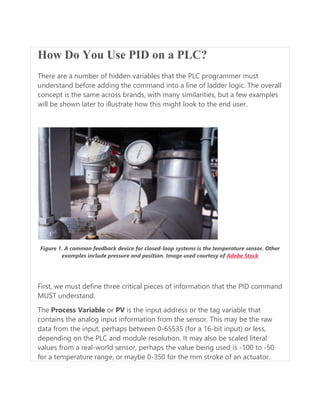
  • 1. How Do You Use PID on a PLC? There are a number of hidden variables that the PLC programmer must understand before adding the command into a line of ladder logic. The overall concept is the same across brands, with many similarities, but a few examples will be shown later to illustrate how this might look to the end user. Figure 1. A common feedback device for closed-loop systems is the temperature sensor. Other examples include pressure and position. Image used courtesy of Adobe Stock First, we must define three critical pieces of information that the PID command MUST understand. The Process Variable or PV is the input address or the tag variable that contains the analog input information from the sensor. This may be the raw data from the input, perhaps between 0-65535 (for a 16-bit input) or less, depending on the PLC and module resolution. It may also be scaled literal values from a real-world sensor, perhaps the value being used is -100 to -50 for a temperature range, or maybe 0-350 for the mm stroke of an actuator.
  • 2. The reason this data must be understood is that the PID command is likely to expect min/max limits from the programmer, if the input PV goes above or below these limits, the program will stop executing and send a fault, indicating a system error. These input limits are sometimes optional. Likewise, the scale of data for the Output must also be understood. If the signal is directly attached to an analog output address for a proportional valve, the output min/max should relate to the resolution of the analog output, maybe the same 0-65535 range, or maybe rather in the -32,768 to 32,767 range if the output is capable of negative voltage outputs. Figure 2. An example of an output device might include a servo-controlled proportional valve for precise hydraulic motion. Image used courtesy of Continental Hydraulics PID Scaling Values Many PLCs differentiate the concepts of a min/max used for scaling versus a min/max limit. While the scaling is used only to compute a linear slope (x input equals y output), this will NOT force an upper or lower limit on the output, it simply means that ‘minimum input equals minimum output, and maximum input equals maximum output’. An extrapolation factor.
  • 3. PID Limit Values A limit, on the other hand, is not used in the computation but is rather used to set alarms and boundaries. If the input goes above or below a limit, the system itself is out of control and may experience damage. If the output goes above or below a limit, the valve or servo may experience harsh stress and damage the final load element. Back to the output variable; the output must be defined with both scale and limit min/max values. If the limit min/max values are set by default, they cannot both be zero, otherwise, the output will always be equal to zero, and the system will appear to be unresponsive. For temperature and flow control processes, the output is often expressed as a percentage, from 0% to 100%, relating to the 0-10v or the 4-20 mA signal to the proportional valve or PWM output. The last of the three critical PID data values (but far from least important) is the Set Point or SP. This value must have the same unit structure as the PV. That means that if the PV is measured in temp degrees, or in mm, or in raw data, then the SP must likewise be defined. The error is the difference (subtraction) between the two data values, so you must have the same units– you can’t subtract 70 degrees from 35,682, that just doesn’t make sense. That difference may be positive or negative, that is an important detail! Example using a Modern PLC System What if we examine an actual example of PID implementation to learn which control values are shown by the command, as well as which items must be considered behind the scenes for proper operation? Let me begin by saying I cannot possibly explain all elements of the tags involved with each PID command and keep the scope to one article. And indeed, if you really need to implement PID for your process, you need to read
  • 4. far more than just this article. However, explaining the basic I/O data and the controlling factors can be a real aid in understanding how to establish the command. PID Command in Rockwell’s Studio 5000 Allen-Bradley ControlLogix and CompactLogix When you drag a PID function block onto a ladder rung, the function will execute as long as the rung is true according to a regularly updated timer. If you wish to have control over the time delay for PID updates, the tag is PID_Name.UPT with a base of milliseconds. PID_Name is whatever name you assign to the PID type tag created in your controller or program scope tag listing. Figure 3. PID command in Studio 5000. In my case, I have created PID_1 with fictitious tags called ‘analog input’ and ‘analog output’ to represent the PV and output (CV). If you have a real analog
  • 5. I/O module, simply use the analog values from these modules. Both of these tags are REAL data types. I set the PID function to update every 10 ms (meaning that the PID_1.UPT tag = 0.01). The scaling values are determined by default when the function is downloaded to the controller, but you can adjust the tags or open the tuning/configuration menu by clicking the three dots in the upper-right corner of the PID function block. To observe the change in this PID function, you can adjust either the SP or the PV to simulate a real-world situation. As you can see from this example, the SP is 80, the PV is so close that the SP that the output is reduced to a very tiny percentage. Note: I excluded Ki (integral gain) from this loop to stabilize the output for getting a screenshot, so the PV will never actually reach the SP exactly. How Does the Scaling Affect the Output? For a simulated scenario, you can adjust the scale of the output and input however you wish, since it’s not connected to an actual responsive device. But remember this: if you link the Control Variable to a real analog output, you must establish a max and min scale that will send the proper value to the analog output tag. For example, if you are using a ControlLogix 1756-OF4, with 4x voltage outputs, the resolution is 15 bits over 0-10 volts. This means that your minimum scale should be 0, and the max scale should be 32,767 (2^15-1). Alternatively, if you are using the current output on this module for a 0-20 mA output, this is rated for 16 bits. So, in this case, the min scale output should be -32,768 (-2^15) while the max scale output remains at 32,767 (2^15-1). These details for this specific module come from pages 183-184 of the user manual. Please do not rely on these numbers for all situations.
  • 6. Most output modules can adapt to devices with 0-10 volt, 0-5 volt, -10 to 10 volt, -20 mA, and 4-20 mA just with some configuration and wiring details, so make sure your output scale matches the type of signal you wish to send. Although it may be impossible to provide an entire scope of coverage for PID controls and programming in one article, it can be helpful to understand the basic functions, then learn how to set them up in a simulated environment to be sure they will respond as accurately as possible to minimize the chance of downtime and failures when the real system is created. Connecting Multiple PLCs to an HMI Learn the basics of connecting multiple PLCs to an HMI using various data types. Most entry-level training for control systems includes programmable logic controllers (PLCs)—ladder programming, wiring inputs and outputs, as well as tag databases and the various data types. Human-machine interface (HMI) programming is a level above this PLC knowledge, but understanding those tag databases in various PLCs can simplify the HMI design process. One of my favorite “experimentation” projects in my own control system setups is to find a new device and figure out how to interface it into a larger system. Obviously, these devices come from a wide variety of vendors, and all must work together. Most common touchscreen HMIs are designed for just this kind of application, allowing multiple systems to simultaneously operate and display data on a central operator screen.
  • 7. Figure 1. Multiple PLCs networked with a single HMI Programming an HMI involves two main components. First, and perhaps most critical, is understanding graphic objects such as buttons, number and text entry fields, graphical data displays, and others. It’s usually fairly simple to follow online tutorials for this step. The other step is what we might call “behind the scenes,” where the objects on the screen actually read or manipulate tags inside the PLC. This may not be so simple, since every PLC has a different tag database structure. HMI Data Types Every PLC has access to the main “atomic” data types, but they can appear differently. Begin with the boolean, or BOOL type. This is a single bit, often an internal status, perhaps a timer or counter termination bit, or an input/output tag. A discrete data type is simply a bool, and needs no further addressing from the controller. If this bool is called “Temp_Alarm_Status”, it can only be ON or
  • 8. OFF. However, any integer can also describe a boolean data bit. In this case, we must specify not only the integer’s name (or memory location), but also which of those integer’s bits is required. Although every integer can be broken down into its component bits, not all of them should be used in this manner. One way to consider this difference is whether the integer represents a value—like an analog temperature or pressure. If so, there is no reason to use this integer in its boolean components. However, if the integer is a string of discrete bits of information, such as data coming across a network connection, or an I/O module consisting of many bools, it would make sense to consider the importance of each discrete bit. Figure 2. A 32-bit DINT named “Current_Temp” defined in the HMI software (Left) and similarly defined in the RSLogix Controller Tags (right) Floating Point (Real) and Char (String) values cannot be expressed as individual bits. Although they are technically built out of 32 bits, or 8 bits for a char, they no longer use each bit as a separate binary place value, like in an integer. There would be no meaningful information extracted from the booleans of these data types.
  • 9. Naturally, those integers, floats, and strings are used everywhere in HMI programs, contributing values. PLC Communication Considerations Within the scope of a single article, I cannot provide a tutorial for every HMI environment and every subject PLC. However, there are numerous similar considerations no matter which software you use. First: the communication protocol. HMIs are designed with a wide variety of network interfaces—the standard being Ethernet, RS-232, or RS-485, but often with adapters for several others. You must be able to select your own PLC and be aware of its network connection protocol. Finally, most screens are limited in the number of simultaneous connections, but they usually allow more than just one. Figure 3. Various HMI communication and programming ports
  • 10. The target PLC will describe its tags with various methods. Tags (variables created in the PLC) are stored within a numbered register address and might be a single bit within that register. Some PLC varieties require you to know this specific address number. Siemens is one example. To point to a single bool, you will need to specify an input, output, or memory, then a register address (perhaps 15), then a bit from that register (like 3). In this example, the bool would be M15.3. An integer would not include the bits themselves, so it might simply be M15. Some PLCs may have an ordered method of assigning a numeric value to each newly created tag. They may each have a prefix to denote the data type. An example of a structure like this is from the Automation Direct Productivity PLC line, where the first created boolean would be C-000001 (C being the designator for a boolean value). A 32-bit integer may be S32-000001, etc. In Allen Bradley Compact/ControlLogix architecture, the structure is by tag name. Each tag created by the user has a unique name, rather than a number. This can simplify the process, as long as the PLC designer assigned logical names to the tags. An example of this tag name method is illustrated in Fig 2.
  • 11. Figure 4. The network switch allows multiple machines to connect to an HMI with only a single Ethernet port Recap To assign multiple PLCs to a single HMI, the biggest obstacle is understanding how different tag databases are organized within the respective PLCs. When adding those tags to the HMI database, select the correct PLC device, add proper tags, and the data transmission between the screen and the controller should be automatic. With a solid understanding of this process, an HMI should be able to monitor and control some pretty impressive systems.
  • 12. Ladder Logic for the Arduino Opta PLC: Creating Your First Program April 05, 2023 by David Peterson     Arduino’s Opta mini PLC platform is supported by the new PLC IDE. Learn to create and download your first program and take advantage of built-in I/O for an easy introduction to the platform. Arduino, the company known and loved around the world for introducing students and professionals to the world of electrical engineering, has made a push in the past year to capture a foothold in the industrial marketplace. Industrial automation can be a challenging field to enter because of strict reliability and security requirements, brand familiarity, and compatibility with existing systems–some of which have been in place for decades.
  • 13. Figure 1. A simple test bench with the Arduino Opta—the ‘USER’ button at the top serves as the programmable input for this intro project. What Arduino Board Supports PLC Programming? Two new hardware platforms have been launched recently to meet various needs in the industrial environment. One of these, the Portenta Machine Control (PMC), was the first to be officially supported by the PLC development software for which you can find tutorials for basic discrete I/O control and more advanced analog and device connections. The second platform, the Arduino Opta, has more recently been added to the list of hardware officially recognized in the PLC IDE. To get started with your very first PLC project on this platform, follow the following program and troubleshooting steps to set up success.
  • 14. Create a New Arduino Opta Project Some of the steps for initial project creation can also be found in our introductory article for the PMC platform. Before getting started, it is recommended to download the most recent version of the IDE and the tools (both free and available from the official Arduino software site). Install both packages, which as of this writing, are version 1.0.3, which indeed supports the Opta platform. After installation, open the software, and create a new project. Give it a name, which I will reference for my own project as Opta_Test_2 from this point forward, and be sure to select ‘Opta 1.0’ as the target. Figure 2. Creating a new project for the Arduino PLC IDE.
  • 15. At this point, you will need to download a first initialization sketch, but only on a complete reset or first use. The overview page should show the image of your Opta PLC, but scroll down until you find the ‘Other’ selection for manual sketch download. There should be a COM port selected (mine was COM 7 on first installation, the COM 5 was added after), then download. Figure 3. First setup and initialization download of the PLC IDE code. After the initial download, you can go online with the Opta PLC (On-line menu -> Connect).
  • 16. The only other setup step is to activate the license. You may need to visit the Arduino online store and purchase a license key, which is relatively inexpensive (less than 20 USD). Author’s note: I previously used the Portenta Machine Control platform on this laptop. When I pressed the button to activate the license for this Opta project, it did so immediately, and it accepted the license after a complete reboot (both the 24 V and USB were removed). I had purchased a license number but wasn’t prompted to enter it. If this is your first time using any Arduino PLC, you may be required to enter the license number. Will update as this information is clarified. Figure 4. After activating the license, be sure the status says ‘OK’ to continue programming.
  • 17. Building Your First PLC Ladder Diagram Before actually plugging in contact and coil commands into a ladder rung, we must first create the right I/O tags, then make sure we have a proper ladder program space in which to build. Mapping Physical I/O in the Opta PLC The Opta provides us with a nice advantage for this ‘beginner intro’ type of program. There is a built-in button on the top of the device with the label of ‘User’. This button doesn’t perform a default function—it’s just a handy button that we can use for simple projects without the need for extra hardware. For the output, we’ll just use a built-in relay output. For experienced PLC users, there will be one warning, but it’s a feature, not a problem! When you program an output to energize, the corresponding LED will NOT light up. They are not connected internally, as most output modules might be. The LEDs are programmable separately, including the ‘User’ button, so with a simple program, the relay will audibly ‘click’, but the lights won’t illuminate. Not until we program them, that is! Navigate to the ‘Resources’ tab -> 'Button Inputs' (shown below) -> then assign the one called ‘User’ with the variable name 'User_Button' (shown in the second image below).
  • 18. Figure 5. I/O Mapping. Figure 6. Defining the USER button with a variable of the same name. Repeat this process in the Relay Outputs tab, locate Output 1 (called O1), and name it simply ‘Output_1’. Obviously, for a real-world project, you would use the name of the real-world output device, perhaps a solenoid or motor drive.
  • 19. Create a New Ladder Diagram Program The default ‘main’ program created is structured text (ST). This is a great platform to work with, but for automation engineers, ladder diagrams are often the go-to, so this article uses ladder logic. To create this new Ladder Diagram interface, navigate to the ‘project’ tab (lower left corner). You should see a ‘main’ up near the top, and it will have a default counter program, all in structured text. To create the new LD program, first click on the top-level tree project name, as you can see in the image below–mine is ‘Opta_Test_2’. If you don’t select the top-level project tree, the options for ‘New program’ will be grayed out. Figure 7. Creating the new ladder diagram (LD) program. Select a New program, and you can choose the type, name, and how it will run. ‘Fast’ means that it will be continuously running in a cyclic fashion.
  • 20. Figure 8. Be sure to assign the task, or else the program will not actually execute once downloaded. Troubleshooting tip: If you forget to assign the task at this point, the program will not run when downloaded. But don’t worry! You simply need to tell it when you want it to scan and activate the outputs. All PLCs are like this. If the program is not running, no outputs will energize. In the Project menu, just open the 'Tasks' list, right-click on the 'Fast' task, and add the program from here. Figure 9. Adding a program to the 'Fast' task. Program the Ladder Logic
  • 21. Finally, we can create the ladder program! Double-click on your new program, and there will be a blank input contact and a blank output coil. I had to scroll to the right to see the output coil, but it should be obvious if you have a large screen. A double-click or right-click -> properties allows you to enter the variable names, just as shown below. Figure 10. Our first Arduino Opta ladder logic program! On-line -> Download code, and you should now have a running PLC program! Why Don’t the LEDs Work on My Arduino Opta?
  • 22. As mentioned before, the I/O LEDs are not hard-wired to the I/O pins like on a normal PLC. The Resources tab also has a menu for LED Outputs. Head back over there, and let’s add a variable name to L1 and L8. L1 is the output LED, and L8 is the blue LED beside the ‘User’ button. You can see the variable names I chose below. Figure 11. To energize the LEDs, first assign them the correct variable names. Back in the ladder program, we must command these LEDs to energize any time the input is active and, therefore, when the relay output is also energized. Right-click on the output coil and select ‘coil’, which will add a new output in parallel with the first.
  • 23. Figure 12. Adding the LEDs to the main ladder diagram structure. Re-download, and now the relay output and the LEDs should be working as expected. Debugging Variables Congratulations on your first Arduino Opta program! You can finish here if you’d like, but there is one more useful feature to discuss. You can add variables to a ‘watch table’ to view their status in real-time. This is handy if you think your program should be working but the PLC isn’t responding. Is the program in the code or the hardware? Click on any command or variable in your ladder diagram, like ‘Output_1’. Navigate to the top ‘Debug’ menu and Add symbol to watch.
  • 24. Figure 13. Adding variables (symbols) to a watch list can identify problems in the code and hardware. Now, there will be a new window to the right of your ladder diagram. This will give you the current value of a BOOL, integer, or float so you can more easily view the status (you Arduino folks: this is like the ‘Serial Monitor’ and you know how useful that can be).
  • 25. Figure 14. The watch table when the button is unpressed (left) and then pressed (right). Arduino PLC Ladder Logic Programming Arduino has come a long way since the initial launch of the Uno R3, and many of us have known and loved them since the beginning. Stay tuned to learn more about the constantly evolving PLC and edge capabilities that these products can add to industrial innovation! If you have an Arduino Portenta Machine Control (PMC) and you still wish to learn PLC programming, check out our other tutorial articles for Arduino! Arduino PLC IDE Tutorial 1: Basic Ladder Logic Programming Arduino PLC IDE Tutorial 2: Analog I/O and External Devices If you only have a spare Uno or other similar board, yet are still interested in learning new PLC functions, there are a few other options available to learn and explore. PLC Ladder Logic on an Arduino: Introduction to OpenPLC
  • 26. Recreating PLC Ladder Logic in an Arduino C/C++ IDE Want to test your knowledge of PLCs? You think you N.O. a lot about ladder logic? Are you a normally-open or normally-closed minded engineer? Using the Allen-Bradley Ramp/Soak Controller With a PID March 13, 2020 by Dennis Lynch     This article will focus on using an Allen-Bradley ramp/soak controller with a PID. A previous article on the Introduction to the Ramp/Soak Controller discusses the definition and history of a ramp/soak controller. This article will provide a specific example of a ramps/soak controller being used. If you'd like to review more basic concepts before continuing, please refer to the previous article linked above. Allen-Bradley does not have a built-in ramp feature in their PID or even their PIDE (enhanced PID) instruction. Perhaps this will change in the future, but until then, adding the ramp/soak (RMPS) instruction as the cascade setpoint to the Allen-Bradley PID or PIDE instruction will provide setpoint ramping as well as some very powerful additional features.
  • 27. Using the Controller with a PID The ramp/soak instruction (known as RMPS within the Allen-Bradley PLC) is typically used to control the setpoint of a PID or PIDE (enhanced) instruction. This can be accomplished by connecting the output of the RMPS instruction to one of the setpoint inputs of the PIDE instruction. I will only refer to the PIDE instruction from here forward. A typical implementation of the ramp/soak with a PIDE in the Allen-Bradley Compactlogix controller. View this image here. Image used courtesy of Rockwell Automation. In the example below, the RMPS instruction output (Out) is connected to the PIDE cascade setpoint (SPCascade). In this configuration, the PIDE can still be used without the ramp/soak, or with the ramp/soak when in cascade mode.
  • 28. To store the ramp/soak steps, three REAL (data type) arrays are needed to store the ramp time/rate (RampValue), soak value (SoakValue) and soak time (SoakTime) for each step. To use the ramp/soak feature in the RMPS instruction, the operator needs only to enter a few parameters to set up the ramp/soak profile such as; the number of steps, ramp time for each step, soak value for each step, and soak time for each step. Once these parameters are entered, the RMPS is initialized and placed in manual. The PIDE loop with the RMPS instruction connected to the cascade setpoint is then put in “Cascade”, the RMPS placed in “Auto” and the ramps/soak profile is started. A Non-Traditional Use of the Ramp/Soak Controller In a recent application, I included the RMPS instruction with each PID loop on the project as a standard feature for the operators to use. It wasn’t long before I was getting some unusual requests from our operations personnel for using the ramp/soak in our application. In this application, a small 20 mL reactor that contained a catalyst was fed with flows from up to eight different flow loops. The reactor temperature was controlled by two temperature loops and the pressure in the reactor was controlled by a back pressure control loop. The operators ran tests on the catalyst using criteria provided by research scientists working closely with them. A typical test would involve manipulating the incoming flows for predetermined durations with the reactor at a given pressure and temperature. This was all done by the operator diligently monitoring the system and adjusting the setpoints at the given time as required by the test plan.
  • 29.
  • 30. A (somewhat daunting) but comprehensive ramp/soak control screen for a catalyst test facility. View the full image here. I was asked if the system could be programmed to automatically adjust the setpoints for each of the different test plans and have the tests run automatically with the operator having to monitor the system constantly. I had added the ramp/soak controller to the flow loops primarily for the setpoint ramping feature, but soon realized that the operators could program all the required flows, temperature, and pressure setpoints along with ramp and soak times into the ramp/soak controllers and have the system run the tests automatically. All that was needed was a comprehensive interface where the operator could see all the ramp/soak setpoints in one place to help them layout the test plan. Below is a screenshot of the somewhat daunting control screen I came up with for the task. Benefits of Using a Ramp/Soak Controller In this application, the ramp/soak controllers work in concert across multiple control loops and somewhat resemble the operation of a sequencer but without the programming to go along with a sequencer. The system is very flexible and has even allowed the tests to be conducted overnight and unattended. This allows the researchers to gather their data in less time as they can run multiple eight-hour tests a day instead of just one during the operator’s shift. The RMPS instruction that is included in the Allen-Bradley PLCs is flexible enough to provide both the basic essential functions of a ramp/soak controller as well as some advanced functions that you would normally see in such a controller.
  • 31. I consistently add the RMPS instruction to all of the PID loops that I program as an additional feature that operators have now come to expect as a standard part of the control loop. Industry 4.0 Changes Selection Criteria For Machine Control Architecture: Why IPC Now Prevails over PLC and PAC for Machine Control September 28, 2022 by KINGSTAR    
  • 32. Learn the differences between PLC, PAC and IPC based machine controls, while exploring how Industry 4.0 changes the requirements for a valuable machine control architecture. White Paper Overview Today’s more flexible, faster, smarter machines can communicate with one other and process/analyze data in real-time, creating game-changing economic and productivity opportunities. Importantly, information sharing via Industry 4.0 standards combined with artificial intelligence will only increase the speed with which demands will be put on the system. Companies offering machine-automation and machine-control systems that are the most flexible, precise and highest-performing will generate the most value for their customers.
  • 33. This white paper will describe the differences between PLC, PAC and IPC based machine controls, while exploring how Industry 4.0 changes the requirements for a valuable machine control architecture and explains why the IPC now offers, by far, the best machine control architecture compared to PLC or PAC. Read White Paper: Already an Control.com member? Please Click Here to login. Fields containing * are required