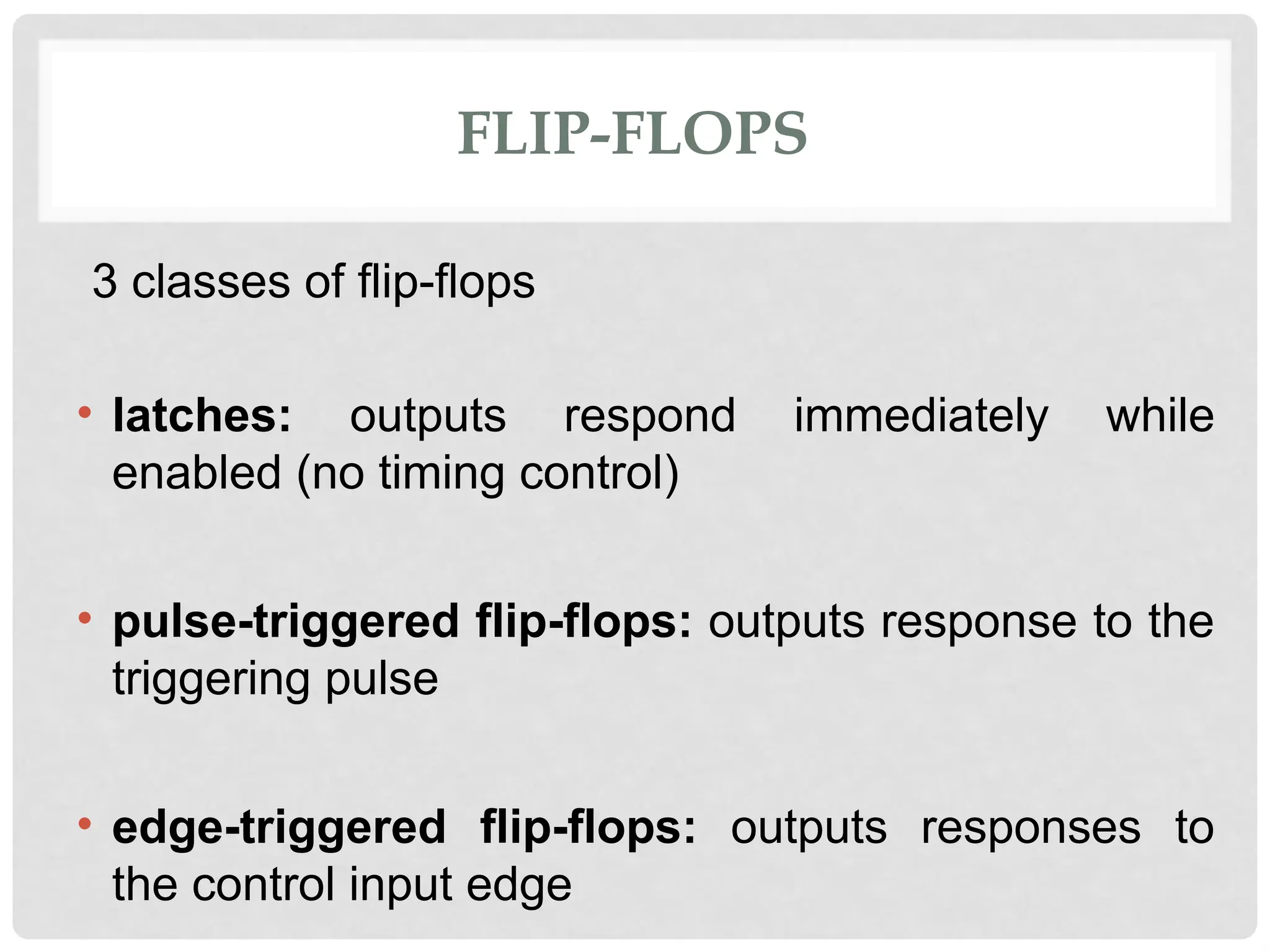
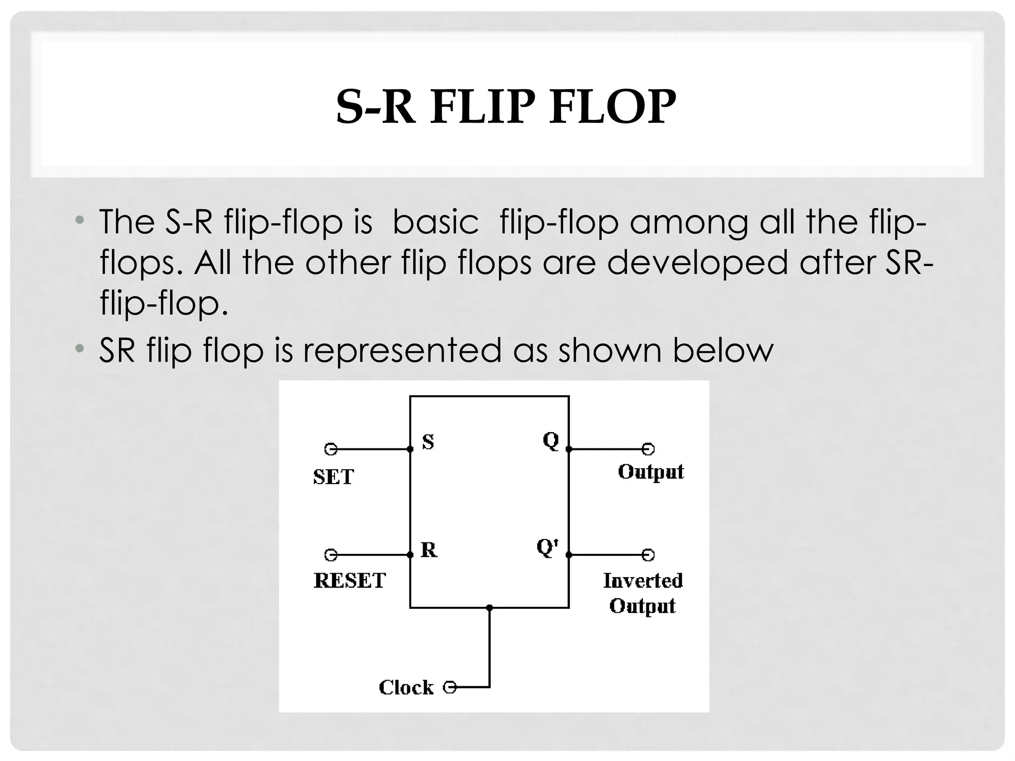
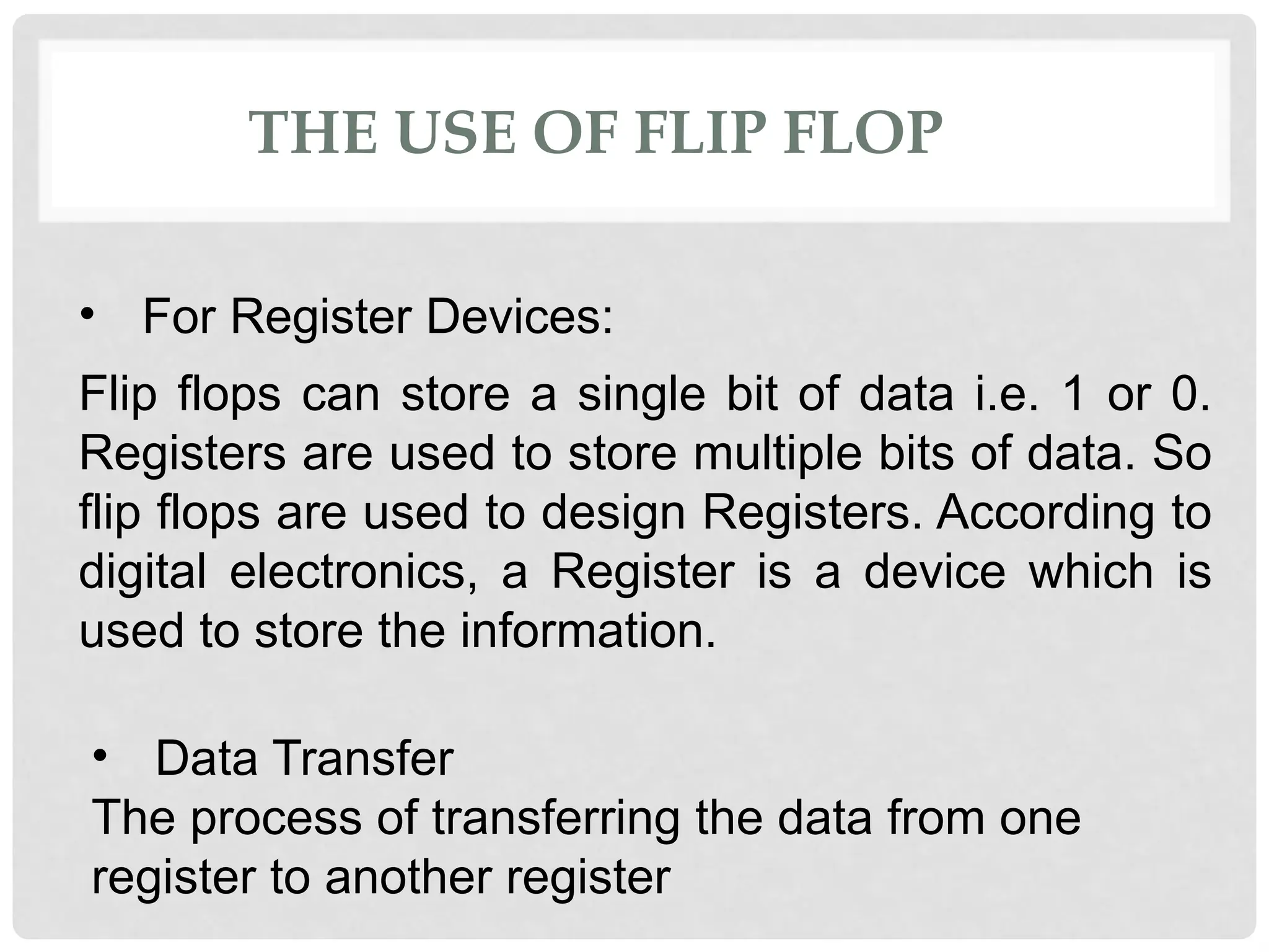
Flip-flops are bistable multivibrators that can store binary data and change between two stable states (high and low) under the influence of a control signal. They can be classified into three types: latches, pulse-triggered, and edge-triggered flip-flops, with specific varieties including S-R, J-K, D, and T flip-flops, each having unique operational characteristics and uses. Flip-flops are crucial in digital circuits for data storage and control of functionality, serving as fundamental components in register devices.


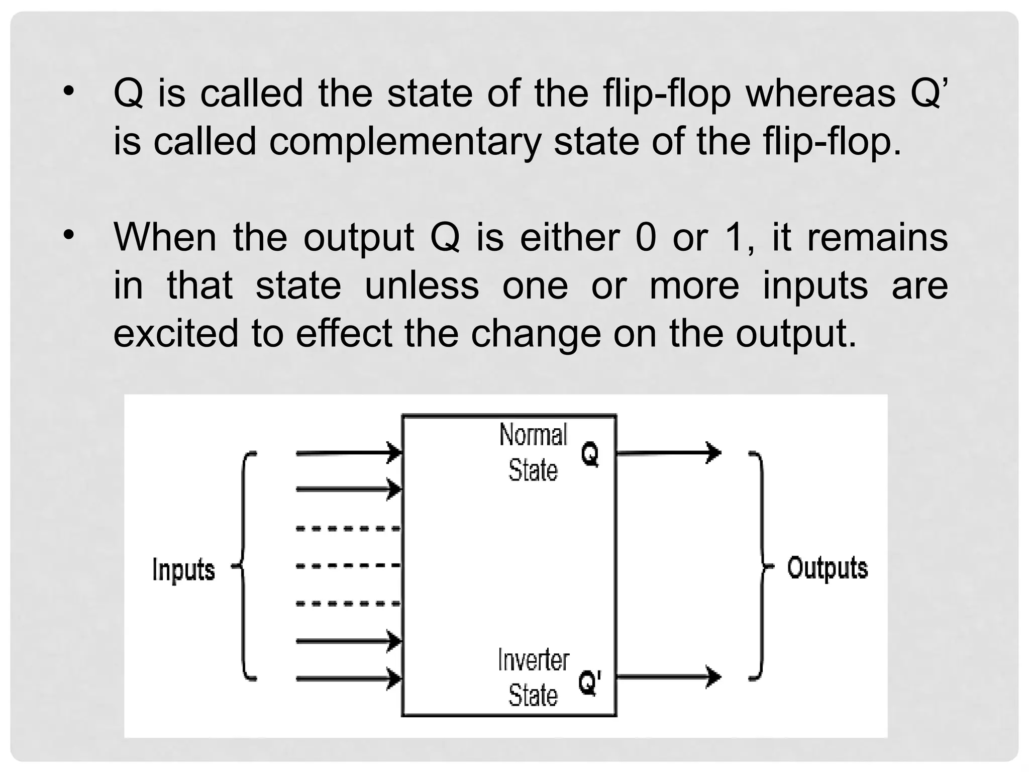
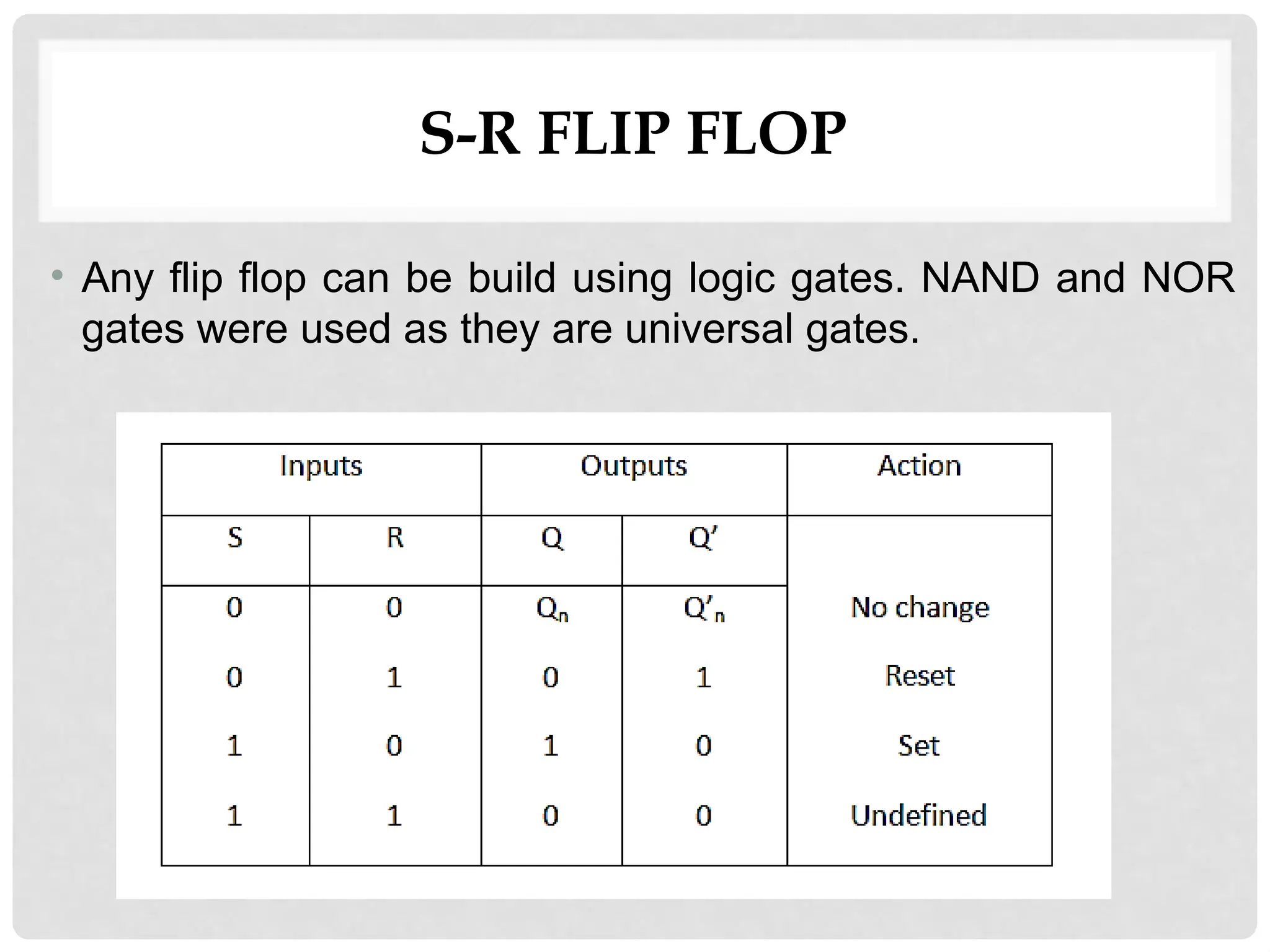

![S=0, R=0 — Q & Q’= Remember
If both the values of S and R are switched to 0,
then the circuit remembers the value of S and
R in their previous state.
S=1, R=1—Q=0, Q’=0 [Invalid]
• This is an invalid state because the values of
both Q and Q’are 0.
• They are supposed to be compliments of
each other. Normally, this state must be
avoided.](https://image.slidesharecdn.com/9flipflopsupdated-1910161406581-241127045649-405a7d7b/75/Flipflopsupdated-explanation-and-applications-pptx-13-2048.jpg)


![Flip_flops_in_digital_electronics[1].pptx](https://cdn.slidesharecdn.com/ss_thumbnails/flipflopsindigitalelectronics1-250805201909-5c7c72ae-thumbnail.jpg?width=640&height=640&fit=bounds)
![Flip_flops_in_digital_electronics[1].pptx](https://cdn.slidesharecdn.com/ss_thumbnails/flipflopsindigitalelectronics1-250805201548-623d4f88-thumbnail.jpg?width=640&height=640&fit=bounds)