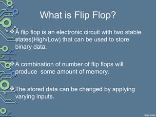
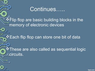
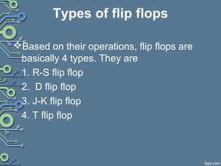
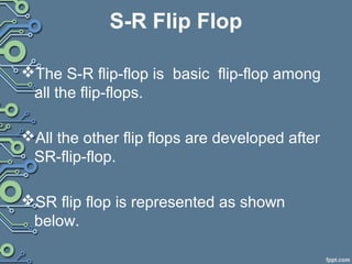
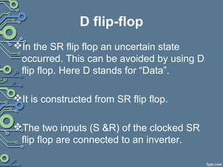
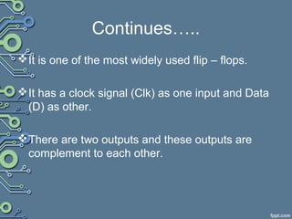
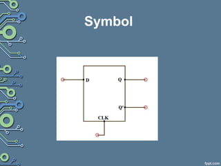
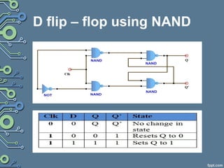
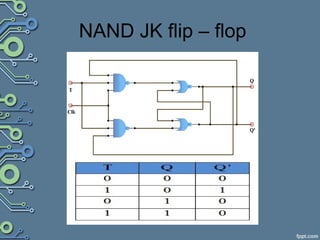
Computers and calculators use
Flip-flop for their memory??
A flip flop is an electronic circuit with two stable states(High/Low) that can be used to store binary data.
flip flop,introduction,types,. SR Flip Flop
a.SR Flip Flop Active Low = NAND gate Latch
b. SR Flip Flop Active High = NOR gate Latch
2. Clocked SR Flip Flop
3. JK Flip Flop
4. JK Flip Flop With Pre-set And Clear
5. T Flip Flop
6. D Flip Flop
7. Master-Slave Edge-Triggered Flip-Flop
The Used of Flip Flop:
This document discusses latches and flip-flops. It describes the SR latch, gated SR latch, D latch, and gated D latch. It also covers edge-triggered flip-flops including the SR, D, and JK flip-flops. The key uses of flip-flops are for data storage, data transfer, counting, and frequency division in digital circuits and sequential logic.
This document provides an introduction and overview of flip flops and RS latches. It defines a flip flop as a circuit that has two stable states and can store state information. It describes the main types of flip flops as asynchronous and synchronous, and lists some examples like the RS latch and JK flip flop. It then explains the key differences between asynchronous and synchronous circuits. The document proceeds to describe the RS latch in more detail, including providing its block diagram, logical diagram using NAND gates, truth table, and descriptions of its inputs, outputs, operation, and states.
JK flip-flops have two outputs, Q and Q', and four modes of operation: hold, set, reset, toggle. The primary output is Q. There are two stable states that can store state information. JK flip-flops are used for data storage in registers, counting in counters, and frequency division. They can divide the frequency of a periodic waveform in half by toggling on each input clock pulse.
1. A flip-flop is a basic element of sequential circuits that has two stable states and whose output depends on both the current input and its previous state.
2. An SR flip-flop can be constructed using two NOR gates, with states that are set by a high S input and reset by a high R input.
3. Gated flip-flops only change state in response to changes at the clock input, allowing the circuit response to be controlled at specific times.
The document explains about the concepts of sequential circuits in Digital electronics.
This will be helpful for the beginners in VLSI and electronics students.
The document discusses flip-flops, which are basic electronic circuits that have two stable states and can serve as one bit of digital memory. It defines what a flip-flop is and describes several common types of flip-flops, including SR, JK, T, D, and master-slave edge-triggered flip-flops. The document provides brief explanations of how each flip-flop type works and is implemented using logic gates.
This document discusses different types of counters used in digital circuits. It defines a counter as a sequential circuit that cycles through a sequence of states in response to clock pulses. Binary counters count in binary and can count from 0 to 2n-1 with n flip-flops. Asynchronous counters have flip-flops that are not triggered simultaneously by a clock, while synchronous counters use a common clock for all flip-flops. Other counter types include ring counters, Johnson counters, and decade counters. The document provides examples of binary, asynchronous, and synchronous counters and discusses their applications in areas like timing sequences and addressing memory.
This document discusses different types of flip flops including S-R, D, J-K, and T flip flops. It provides circuit diagrams and truth tables for each type. S-R flip flops can be made using NOR or NAND gates and have set, reset, and memory states. D flip flops are a modification of clocked S-R flip flops and pass the input to the output on a clock pulse. J-K flip flops are also based on S-R flip flops and toggle the output when both inputs are high. T flip flops are a simplified version of J-K flip flops where the two inputs are connected, causing the output to toggle with each clock
This document discusses different types of flip-flops, which are basic sequential circuits that have two stable states and can store one bit of data. It describes common flip-flop types like the S-R latch, clocked S-R flip-flop, J-K flip-flop, D flip-flop, and T flip-flop. It also covers the master-slave J-K flip-flop configuration and differences between latches and flip-flops. Flip-flops have applications in registers, frequency dividers, and digital counters.
In electronics, a flip-flop or latch is a circuit that has two stable states and can be used to store state information – a bistable multivibrator. The circuit can be made to change state by signals applied to one or more control inputs and will have one or two outputs.
This document summarizes sequential circuits and their basic components - latches and flip-flops. It describes how latches like the SR, S'R', and D latches work based on inputs but no clock signal, while flip-flops like edge-triggered flip-flops change state based on the clock edge. Examples of additional flip-flop inputs like preset, clear and clock enable are provided to control the output independent of the clock. Asynchronous sequential circuits can override the clock input using preset and clear inputs to directly control the output states.
Sequential circuits consist of combinational logic and memory elements like latches and flip-flops. There are different types of latches and flip-flops that differ in their trigger mechanisms and outputs, including SR latches, D latches, and edge-triggered flip-flops like SR, D, and JK flip-flops. Asynchronous inputs can directly set or reset flip-flop outputs independent of the clock signal.
The document discusses sequential circuits and different types of flip flops and counters. It describes how sequential circuits have memory and their output depends on current and past inputs. There are two main types of sequential circuits - asynchronous which can change state at any time and synchronous which use a clock signal to control when the output can change state. Common types of flip flops described include SR, JK, D and T flip flops. Counters can be asynchronous with the clock signal rippling through or synchronous where all flip flops share the same clock.
This presentation summarizes different types of flip flops used in digital circuits. It is presented by a group called Bug Free and includes 4 members. The presentation defines a flip flop as an electronic circuit with two stable states that can serve as one bit of memory. It then describes 5 main types of flip flops - SR, Clocked SR, JK, T, and D flip flops. Examples of each type of flip flop are shown using logic gates. Applications of flip flops mentioned include memory circuits, logic control devices, counters, and registers. A master-slave edge-triggered flip flop is also summarized.
JK & MASTER SLAVE FLIP-FLOP
The document discusses the JK flip-flop, which removes invalid states that occur in other flip-flops. The JK flip-flop has inputs for J, K, preset, clear, and clock, and outputs of Q and Q'. It operates in four modes - hold, set, reset, toggle - based on the states of J and K. A master-slave JK flip-flop uses two JK flip-flops connected by an inverter to avoid race-around conditions, with the master capturing the input on the rising clock edge and the slave outputting it on the falling edge.
This document discusses different types of flip-flops including edge-triggered flip-flops like the S-R, D, and J-K flip-flops. It describes their characteristics such as how their output changes depending on the input and clock signal. The S-R flip-flop can be set or reset. The D flip-flop copies its input to the output on the clock edge. The J-K flip-flop can toggle its output. The T flip-flop is a single-input version of the J-K flip-flop that toggles its output. Flip-flops have applications in data transfer and frequency division.
This document discusses latches and flip flops, which are types of sequential logic circuits. It describes the basic components and functioning of latches like SR latches, D latches, and gated latches. For flip flops, it covers SR flip flops, D flip flops, JK flip flops, and master-slave flip flops. The key differences between latches and flip flops are that latches do not have a clock input while flip flops are edge-triggered by a clock signal. Latches and flip flops are used as basic storage elements in more complex sequential circuits and in computer components like registers and RAM.
The document discusses the design and analysis of a D-flip flop. It begins by introducing flip flops and their use for storing state information. It then discusses the need for a D-flip flop due to limitations in the basic SR flip flop. A D-flip flop overcomes these limitations using a gated SR flip flop with an inverter between the S and R inputs, allowing a single data input. The circuit and working of the D-flip flop are shown, noting it will store and output the data input while the clock is high.
This document discusses decoders and encoders. It defines a decoder as a circuit that accepts a binary input and activates only one output corresponding to the input. An encoder is the inverse, converting an active input to a coded output. Various types of decoders and encoders are described, including 2-to-4 decoders, 3-to-8 decoders, priority encoders, decimal-to-BCD encoders, and octal-to-binary encoders. Truth tables and logic diagrams are provided as examples. Expansion of decoders using multiple lower-order decoders is also covered.
Flip-flops are basic memory circuits that have two stable states and can store one bit of information. There are several types of flip-flops including SR, JK, D, and T. The SR flip-flop has two inputs called set and reset that determine its output state, while the JK flip-flop's J and K inputs can toggle its output. Flip-flops like the D and JK can be constructed from more basic flip-flops. For sequential circuits, flip-flops are made synchronous using a clock input so their state only changes at the clock edge.
1. Flip-flops and latches are types of memory elements used in sequential circuits. Latches change state based on input levels while flip-flops change state only on the rising or falling edge of a clock signal.
2. Common types of latches include the SR latch and D latch. Common types of flip-flops include the D flip-flop, JK flip-flop, and T flip-flop. Each has a characteristic truth table that defines its operation.
3. Sequential circuits can be analyzed using state tables that define the next state based on the present state and inputs. The state is defined by the values stored in all memory elements of the circuit.
A multiplexer is a device that selects one of several analog or digital input signals and forwards the selected input into a single line. It has multiple data inputs, a single output, and select lines that determine which input is directed to the output. A demultiplexer performs the opposite function, taking a single input and distributing it to one of multiple outputs based on the select lines. Multiplexers and demultiplexers come in various configurations depending on the number of inputs and outputs, such as 2:1, 4:1, 16:1 or 32:1. They are basic building blocks used in digital systems and communication networks to efficiently route signals.
1) The document discusses sequential logic circuits and flip-flops. It defines sequential logic as circuits whose output depends on the previous inputs and states, requiring memory elements like flip-flops.
2) Flip-flops are described as basic memory storage elements that have two stable states and can be switched between them. Common types include SR, JK, D and T flip-flops.
3) SR and T flip-flops are discussed in detail. Their symbols, truth tables, and implementations using logic gates are presented. SR flip-flops can be built using NOR or NAND gates and can be set, reset, or held in state based on input conditions.
The Reason Why we use master slave JK flip flop instead of simple level triggered flip flop is Racing condition which can be successfully avoided using two SR latches fed with inverted clocks.
The D flip-flop is a modified form of the SR flip-flop that overcomes the shortcoming of invalid or indeterminate output when both S and R inputs are logic 0. It ensures the S and R inputs are never equal using an inverter between the inputs to allow a single D (data) input. The D flip-flop's truth table and characteristic table show that the next state Q(n+1) will always equal the current D input regardless of the clock or current state Qn. This simplified design makes D flip-flops useful in applications like data transfer, counters, registers, and frequency dividers.
ppt on flip flops
contents :
Made by : Dhanesh RK Nair
WHAT IS FLIP FLOP?
In digital circuits, the flip-flop, is a kind of bistable multivibrator.
It is a Sequential Circuits / an electronic circuit which has two stable states and thereby is capable of serving as one bit of memory , bit 1 or bit 0.
TYPES OF FLIP FLOPS:
1. SR Flip Flop
2. Clocked SR Flip Flop
3. JK Flip Flop
4. JK Flip Flop With Preset And Clear
5. T Flip Flop
6. D Flip Flop
USES OF FLIP FLOPS:
For Memory circuits
For Logic Control Devices
For Counter Devices
For Register Devices
SR FLIP FLOP
The most basic Flip Flop is called SR Flip Flop.
The basic RS flip flop is an asynchronous device.
In asynchronous device, the outputs is immediately changed anytime one or more of the inputs change just as in combinational logic circuits.
It does not operate in step with a clock or timing.
CLOCKED SR FLIP FLOP
Additional clock input is added to change the SR flipflop from an element used in asynchronous sequential circuits to one, which can be used in synchronous circuits.
The clocked SR flip flop logic symbol that is triggered by the PGT
Its means that the flip flop can change the output states only when clock signal makes a transition from LOW to HIGH.
JK FLIP FLOP
Another types of Flip flop is JK flip flop.
It differs from the RS flip flops when J=K=1 condition is not indeterminate but it is defined to give a very useful changeover (toggle) action.
Toggle means that Q and Q(compliment) will switch to their opposite states.
The JK Flip flop has clock input Cp and two control inputs J and K.
Operation of Jk Flip Flop is completely described by truth table
T FLIP FLOP
The T flip flop has only the Toggle and Hold Operation.
If Toggle mode operation. The output will toggle from 1 to 0 or vice versa.
D FLIP FLOP
Also Known as Data Flip flop
Can be constructed from RS Flip Flop or JK Flip flop by addition of an inverter.
Inverter is connected so that the R input is always the inverse of S (or J input is always complementary of K).
The D flip flop will act as a storage element for a single binary digit (Bit).
THANKS....!!!!
SOME MORE CONTENTS :
In electronics, a flip-flop or latch is a circuit that has two stable states and can be used to store state information. A flip-flop is a bistable multivibrator. The circuit can be made to change state by signals applied to one or more control inputs and will have one or two outputs. It is the basic storage element in sequential logic. Flip-flops and latches are fundamental building blocks of digital electronics systems used in computers, communications, and many other types of systems.
Flip-flops and latches are used as data storage elements. A flip-flop stores a single bit (binary digit) of data; one of its two states represents a "one" and the other represents a "zero". Such data storage can be used for storage of state, and such a circuit is described as sequential logic.
THANKS!!!!!!!!!!!
Latches are asynchronous electronic logic circuits with two stable output states. There are four main types of latches: D, T, SR, and JK latches. An SR latch has two inputs - SET (S) and RESET (R) - and two complementary outputs (Q and Q'). The state of the latch depends on whether input S or R is activated. A D latch similarly has one data input and two complementary outputs, but removes invalid states that can occur in an SR latch. Latches can be either active-high or active-low, depending on whether a high or low input triggers a state change.
This document discusses different types of flip flops used in digital circuits. It introduces flip flops as basic building blocks that can store one bit of data and are used in computer memory. It describes three main types of flip flops: R-S flip flops which can be set or reset, D flip flops which store input data on a clock edge, and J-K flip flops which can toggle their output. For each type, it provides details on their structure using logic gates, inputs/outputs, and truth tables that define their behavior.
1) Flip-flops are basic memory elements that store one bit of information as a 1 or 0. Common types include RS, D, JK, and T flip-flops.
2) Registers are groups of flip-flops that can store multiple bits and perform data processing. Data is loaded into registers by transferring new information during a clock pulse.
3) Master-slave JK flip-flops prevent racing conditions by using two flip-flops triggered on opposite clock edges, with the slave output following the master.
ABOUT FLIP FLOPS IN DIGITAL ELECTRONICS .pptxropide1272
A flip-flop is a digital circuit that has two stable states and is used to store state information. There are four main types of flip-flops: JK, D, T, and SR. The SR flip-flop has two inputs called set and reset that set the output to 1 or 0 respectively. SR flip-flops can also be clocked using NAND or NOR gates to synchronize the changing of states with a clock signal. One application of clocked SR flip-flops is in switch debouncing circuits to eliminate unwanted switching from mechanical switch bounce.
This document discusses various types of flip flops including RS, JK, D, and T flip flops. It provides the theory of sequential circuits and flip flops. It also gives the truth tables and explanations for each type of flip flop. The aim is to verify the truth tables of these flip flops experimentally using logic gates, input switches, and output LEDs. The procedure and result are to check the components, make the circuit connections, provide various input combinations, and note the output to verify the truth tables for each flip flop type.
1. The document discusses different types of flip-flops including D flip-flops, T flip-flops, and JK flip-flops.
2. A flip-flop is a circuit that has two stable states and is used to store digital information. It is the basic storage element in sequential logic.
3. The document provides details on the operation and implementation of different types of flip-flops such as how a D flip-flop stores input data on the rising edge of a clock signal.
This document provides information about sequential logic circuits. It begins by defining sequential logic circuits as consisting of a combinational circuit with storage elements that provide feedback, causing the output to depend on the sequence of inputs. It describes the main types of sequential circuits as synchronous and asynchronous. It also discusses different types of storage elements including latches and flip-flops. Latches are level sensitive while flip-flops are edge triggered. Specific latch and flip-flop circuits like the SR latch, D latch, and JK flip-flop are described along with their operations.
1. The document discusses sequential logic circuits and various types of storage elements used in them, including latches and flip-flops.
2. It describes the basic operation of latches, SR latches, D latches, and various types of flip-flops including RS, JK, T, and D flip-flops.
3. The key differences between latches and flip-flops are explained, with latches being level-sensitive and flip-flops being edge-triggered.
This document discusses different types of flip flops including SR, D, JK, and T flip flops. It provides information on each type of flip flop such as their structure, inputs, outputs, truth tables, and how they work. The document contains sections written by different students that define and explain the basics of each flip flop type including their logic symbol, wiring diagram if applicable, and how their output is determined based on input signals.
REPRESENTATION TO FLIP-FLOPS CHARACTERISTICS TABLE AND FLIP-FLOPS EXCITATION ...recoveraccount1
This document discusses different types of flip-flops, including SR, JK, D-type, and T flip-flops. It provides descriptions of each type of flip-flop: the SR flip-flop is the most basic bistable latch built using NAND or NOR gates; the JK flip-flop is similar to the SR and is commonly used, with J equivalent to set and K to reset; the D-type flip-flop transfers data between its input and outputs after one clock pulse; and the T flip-flop, also called a toggle flip-flop, relates the J and K inputs of a JK flip-flop to disable the AND gates when T=0
This lecture discusses different types of basic flip-flops including SR, D, JK, and T flip-flops. It begins by distinguishing between latches and flip-flops, with latches using level-sensitive control and flip-flops using edge-triggered clock signals. The lecture then covers the operation of SR, D, and JK flip-flops using NAND gates, including their truth tables. It also introduces the T flip-flop as a variation of the JK flip-flop with its single input T causing the output to toggle states. The concept of a "race around condition" is explained for the JK flip-flop where feedback from the output to the input can cause the output
This document discusses different types of flip-flops including SR, JK, D, and T flip-flops. It provides details on the construction, logic circuits, symbols, and truth tables of SR and JK flip-flops. SR flip-flops are the simplest type and can be constructed using NOR or NAND latches along with AND or NAND gates. JK flip-flops were introduced to solve the indeterminate state problem of SR flip-flops when both inputs are 1. They can be constructed using SR flip-flops made from NOR latches along with additional connections. The document also briefly mentions that D flip-flops track the input and store the value on the data line,
The document provides information about various types of digital logic circuits including flip-flops, microcontrollers, and computer architectures. It describes the basic operation and applications of SR, JK, D, and T flip-flops. It also discusses asynchronous and synchronous counters built using flip-flops. The document compares microcontrollers to microprocessors and describes the von Neumann and Harvard computer architectures. It provides details on the Pic 16F628A microcontroller and the hardware and software used for microcontroller programming.
This document provides an introduction to sequential circuits and various types of flip-flops. It discusses the differences between combinational and sequential circuits, and describes SR, D, JK, T, and JK flip-flops. Their block diagrams, truth tables, characteristic tables, and excitation tables are presented. Applications of flip-flops such as counters, frequency dividers, shift registers, and data storage are also covered briefly. Finally, the document discusses various types of shift registers including serial-in serial-out, serial-in parallel-out, parallel-in serial-out, and parallel-in parallel-out.
This document discusses latches and flip-flops. It begins by explaining the difference between latches and flip-flops, noting that latches do not have a clock signal while flip-flops do. It then discusses several types of flip-flops - RS, Clocked RS, D, JK, and T - providing the definition, explanation, circuit diagram, and truth table for each. It also discusses several types of latches - SR, Gated SR, and D - providing the definition, explanation, and circuit diagram for each. The document aims to explain the key characteristics and workings of various latches and flip-flops.
What are Flip Flops and Its types. What are Flip Flops and Its types. What are Flip Flops and Its types. What are Flip Flops and Its types. What are Flip Flops and Its types. What are Flip Flops and Its types. What are Flip Flops and Its types.
Flip flops are basic memory elements that store one bit of information as a 1 or 0. Common types include RS, D, JK, T, and master-slave JK flip flops. Flip flops have two stable states and two complementary outputs. They are used as registers for storage, in frequency dividers, and digital counters. Registers consist of groups of flip flops that hold information, while shift registers can shift data in one or both directions using cascaded flip flops and clock pulses. Flip flops have applications in interfacing digital systems, as delay circuits, and for converting between serial and parallel data.
The document discusses sequential logic and flip-flops. It begins by defining sequential logic and introducing flip-flops. It then discusses different types of flip-flops including SR, JK, D, and T flip-flops. It describes their operation, truth tables, and how they are constructed using logic gates. The document also covers triggering methods for flip-flops including master-slave and edge triggering. Finally, it discusses modeling sequential circuits using state equations, state tables, and state diagrams.
This document provides an overview of sequential circuits and flip-flops. It discusses the objectives of sequential circuits and various types of flip-flops like SR, JK, D and T flip-flops. It explains what flip-flops are, how they work, and where they are used. It also covers the conversions between different types of flip-flops like SR to JK, JK to SR, SR to D, and D to SR. Diagrams and truth tables are provided to illustrate these conversions.
The document discusses sequential logic and flip-flops. It provides information on different types of flip-flops including SR, JK, D, and T flip-flops. It describes how flip-flops work, their truth tables, and how they can be triggered either by pulses or edges of a clock signal. It also discusses state equations, state tables, and state diagrams which can be used to analyze sequential circuits and describe their behavior over time. Finally, it introduces the Mealy and Moore models which are two common models for sequential circuits that differ in how outputs are generated.
Edge Trigged Flip Flpps, this presentation will cover the following topics
Flip Flops
Properties of flip flops
Edge trigged flip flops
THE EDGE TRIGGERED S-R FLIP FLOPS
THE EDGE TRIGGERED J-K FLIP FLOPS
THE EDGE TRIGGERED D FLIP FLOPS
THE EDGE TRIGGERED T FLIP FLOPS
Operating characteristics of edge trigged flip flops
Digital Twins Computer Networking Paper Presentation.pptxaryanpankaj78
A Digital Twin in computer networking is a virtual representation of a physical network, used to simulate, analyze, and optimize network performance and reliability. It leverages real-time data to enhance network management, predict issues, and improve decision-making processes.
Design and optimization of ion propulsion dronebjmsejournal
Electric propulsion technology is widely used in many kinds of vehicles in recent years, and aircrafts are no exception. Technically, UAVs are electrically propelled but tend to produce a significant amount of noise and vibrations. Ion propulsion technology for drones is a potential solution to this problem. Ion propulsion technology is proven to be feasible in the earth’s atmosphere. The study presented in this article shows the design of EHD thrusters and power supply for ion propulsion drones along with performance optimization of high-voltage power supply for endurance in earth’s atmosphere.
Prediction of Electrical Energy Efficiency Using Information on Consumer's Ac...PriyankaKilaniya
Energy efficiency has been important since the latter part of the last century. The main object of this survey is to determine the energy efficiency knowledge among consumers. Two separate districts in Bangladesh are selected to conduct the survey on households and showrooms about the energy and seller also. The survey uses the data to find some regression equations from which it is easy to predict energy efficiency knowledge. The data is analyzed and calculated based on five important criteria. The initial target was to find some factors that help predict a person's energy efficiency knowledge. From the survey, it is found that the energy efficiency awareness among the people of our country is very low. Relationships between household energy use behaviors are estimated using a unique dataset of about 40 households and 20 showrooms in Bangladesh's Chapainawabganj and Bagerhat districts. Knowledge of energy consumption and energy efficiency technology options is found to be associated with household use of energy conservation practices. Household characteristics also influence household energy use behavior. Younger household cohorts are more likely to adopt energy-efficient technologies and energy conservation practices and place primary importance on energy saving for environmental reasons. Education also influences attitudes toward energy conservation in Bangladesh. Low-education households indicate they primarily save electricity for the environment while high-education households indicate they are motivated by environmental concerns.
Redefining brain tumor segmentation: a cutting-edge convolutional neural netw...IJECEIAES
Medical image analysis has witnessed significant advancements with deep learning techniques. In the domain of brain tumor segmentation, the ability to
precisely delineate tumor boundaries from magnetic resonance imaging (MRI)
scans holds profound implications for diagnosis. This study presents an ensemble convolutional neural network (CNN) with transfer learning, integrating
the state-of-the-art Deeplabv3+ architecture with the ResNet18 backbone. The
model is rigorously trained and evaluated, exhibiting remarkable performance
metrics, including an impressive global accuracy of 99.286%, a high-class accuracy of 82.191%, a mean intersection over union (IoU) of 79.900%, a weighted
IoU of 98.620%, and a Boundary F1 (BF) score of 83.303%. Notably, a detailed comparative analysis with existing methods showcases the superiority of
our proposed model. These findings underscore the model’s competence in precise brain tumor localization, underscoring its potential to revolutionize medical
image analysis and enhance healthcare outcomes. This research paves the way
for future exploration and optimization of advanced CNN models in medical
imaging, emphasizing addressing false positives and resource efficiency.
Build the Next Generation of Apps with the Einstein 1 Platform.
Rejoignez Philippe Ozil pour une session de workshops qui vous guidera à travers les détails de la plateforme Einstein 1, l'importance des données pour la création d'applications d'intelligence artificielle et les différents outils et technologies que Salesforce propose pour vous apporter tous les bénéfices de l'IA.
VARIABLE FREQUENCY DRIVE. VFDs are widely used in industrial applications for...PIMR BHOPAL
Variable frequency drive .A Variable Frequency Drive (VFD) is an electronic device used to control the speed and torque of an electric motor by varying the frequency and voltage of its power supply. VFDs are widely used in industrial applications for motor control, providing significant energy savings and precise motor operation.
Advanced control scheme of doubly fed induction generator for wind turbine us...IJECEIAES
This paper describes a speed control device for generating electrical energy on an electricity network based on the doubly fed induction generator (DFIG) used for wind power conversion systems. At first, a double-fed induction generator model was constructed. A control law is formulated to govern the flow of energy between the stator of a DFIG and the energy network using three types of controllers: proportional integral (PI), sliding mode controller (SMC) and second order sliding mode controller (SOSMC). Their different results in terms of power reference tracking, reaction to unexpected speed fluctuations, sensitivity to perturbations, and resilience against machine parameter alterations are compared. MATLAB/Simulink was used to conduct the simulations for the preceding study. Multiple simulations have shown very satisfying results, and the investigations demonstrate the efficacy and power-enhancing capabilities of the suggested control system.
3. What is Flip Flop?
A flip flop is an electronic circuit with two stable
states(High/Low) that can be used to store
binary data.
A combination of number of flip flops will
produce some amount of memory.
The stored data can be changed by applying
varying inputs.
4. Continues…..
Flip flop are basic building blocks in the
memory of electronic devices
Each flip flop can store one bit of data
These are also called as sequential logic
circuits.
5. Continues….
They are used in computers,
communications, and many other types of
systems.
Flip-flops and are used as data storage
elements.
It is the basic storage element in
sequential logic.
6. Types of flip flops
Based on their operations, flip flops are
basically 4 types. They are
1. R-S flip flop
2. D flip flop
3. J-K flip flop
4. T flip flop
7. S-R Flip Flop
The S-R flip-flop is basic flip-flop among
all the flip-flops.
All the other flip flops are developed after
SR-flip-flop.
SR flip flop is represented as shown
below.
8. Continues….
S-R stands for SET and RESET. This can
also be called RS flip-flop. Difference is
RS is inverted SR
NAND and NOR gates were used as they
are universal gates.
11. D flip-flop
In the SR flip flop an uncertain state
occurred. This can be avoided by using D
flip flop. Here D stands for “Data”.
It is constructed from SR flip flop.
The two inputs (S &R) of the clocked SR
flip flop are connected to an inverter.
12. Continues…..
It is one of the most widely used flip – flops.
It has a clock signal (Clk) as one input and Data
(D) as other.
There are two outputs and these outputs are
complement to each other.
16. J-K Flip Flop
JK flip – flop is named after Jack Kilby, an
electrical engineer who invented IC.
A JK flip – flop is a modification of SR flip
– flop.
In this the J input is similar to the set
input of SR flip – flop and the K input is
similar to the reset input of SR flip – flop
17. Continues……
The condition J = K = 1 which is not allowed in
SR flip – flop (S = R = 1) is interpreted as a
toggle command.
The JK flip flop has
i). Two data inputs J and K.
ii). One clock signal input (CLK).
iii). Two outputs Q and Q’.
19. NAND SR flip – flop.
It is similar to a modified NAND SR flip –
flop.
20. T Flip Flop
T flip flop is also known as “Toggle Flip – flop”.
Toggle is to change the output to complement of
the previous state in the presence of clock input
signal.
The T flip flop has
i). T input.
ii). One clock signal input (CLK).
iii). Two outputs Q and Q’.
23. WHERE WE USE FLIP
FLOPS??
we use them in memory elements like
registers, for data storage.
uses as counters, to count the increment
or decrement of an event occurrence.
Flip flops are used as frequency division
circuits,
24. Continues…
Flip flops are used as frequency division circuits,
frequency division circuits are used to regularize
the frequency of electronic circuits.
We use shift registers (A special-type of
registers) to transfer the data from one flip flop
to another,