Downloaded 499 times
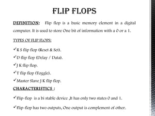

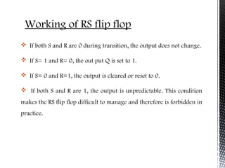
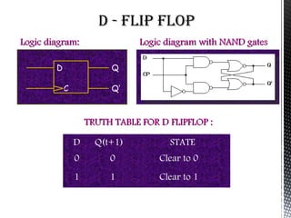
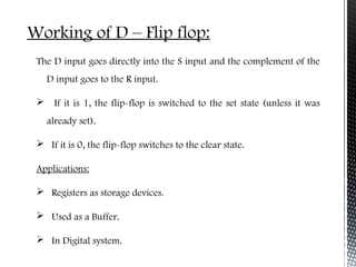
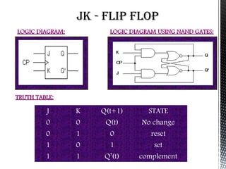

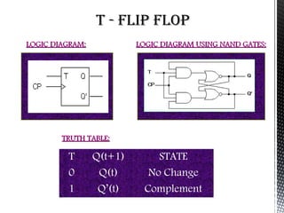
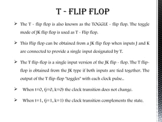
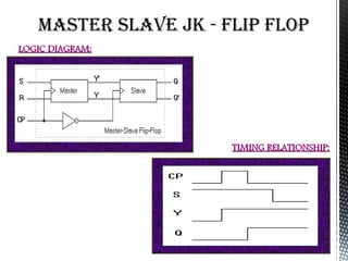
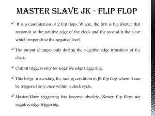


Flip flops are basic memory elements that store one bit of information as a 1 or 0. Common types include RS, D, JK, T, and master-slave JK flip flops. Flip flops have two stable states and two complementary outputs. They are used as registers for storage, in frequency dividers, and digital counters. Registers consist of groups of flip flops that hold information, while shift registers can shift data in one or both directions using cascaded flip flops and clock pulses. Flip flops have applications in interfacing digital systems, as delay circuits, and for converting between serial and parallel data.


![Flip_flops_in_digital_electronics[1].pptx](https://cdn.slidesharecdn.com/ss_thumbnails/flipflopsindigitalelectronics1-250805201909-5c7c72ae-thumbnail.jpg?width=640&height=640&fit=bounds)
![Flip_flops_in_digital_electronics[1].pptx](https://cdn.slidesharecdn.com/ss_thumbnails/flipflopsindigitalelectronics1-250805201548-623d4f88-thumbnail.jpg?width=640&height=640&fit=bounds)