Downloaded 153 times

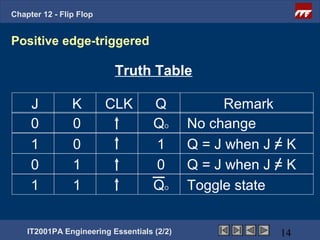
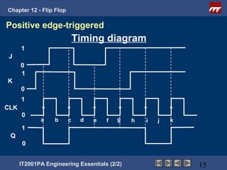
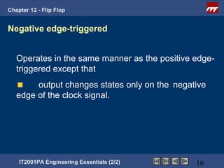
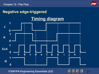
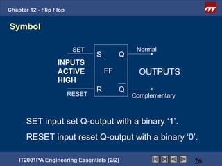
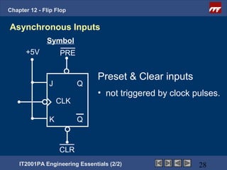
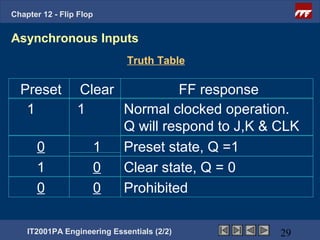
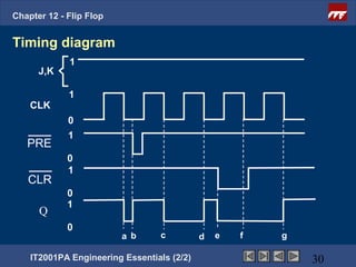
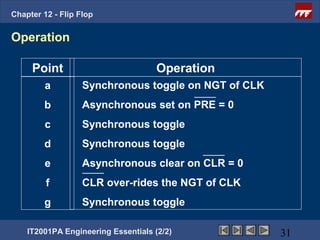
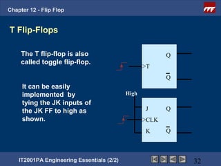
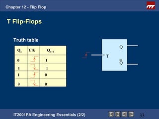
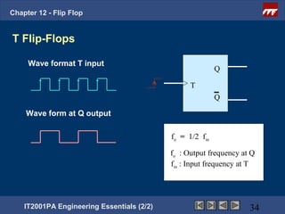

This document provides an overview of flip-flops, which are digital circuits that function as memory elements. It describes the objectives and specific learning outcomes of understanding various types of flip-flops including JK, D, and T flip-flops. The key aspects covered include their symbols, truth tables, logic circuits, and applications in digital systems. Edge-triggered and level-triggered operations are also compared.