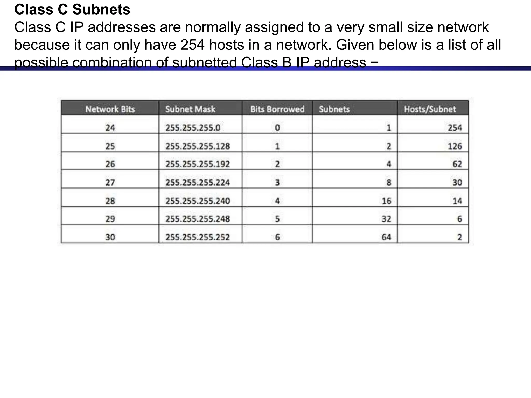
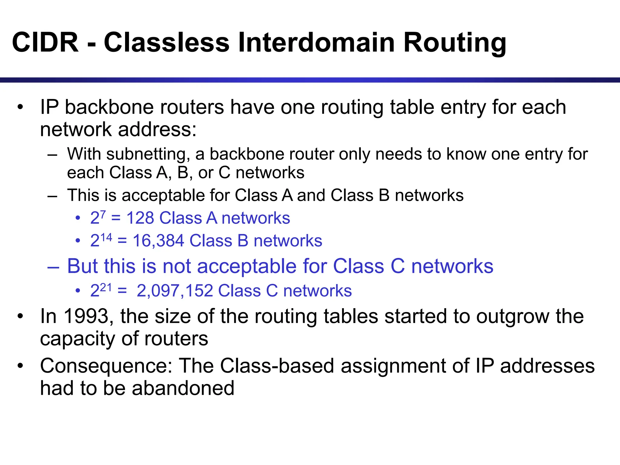
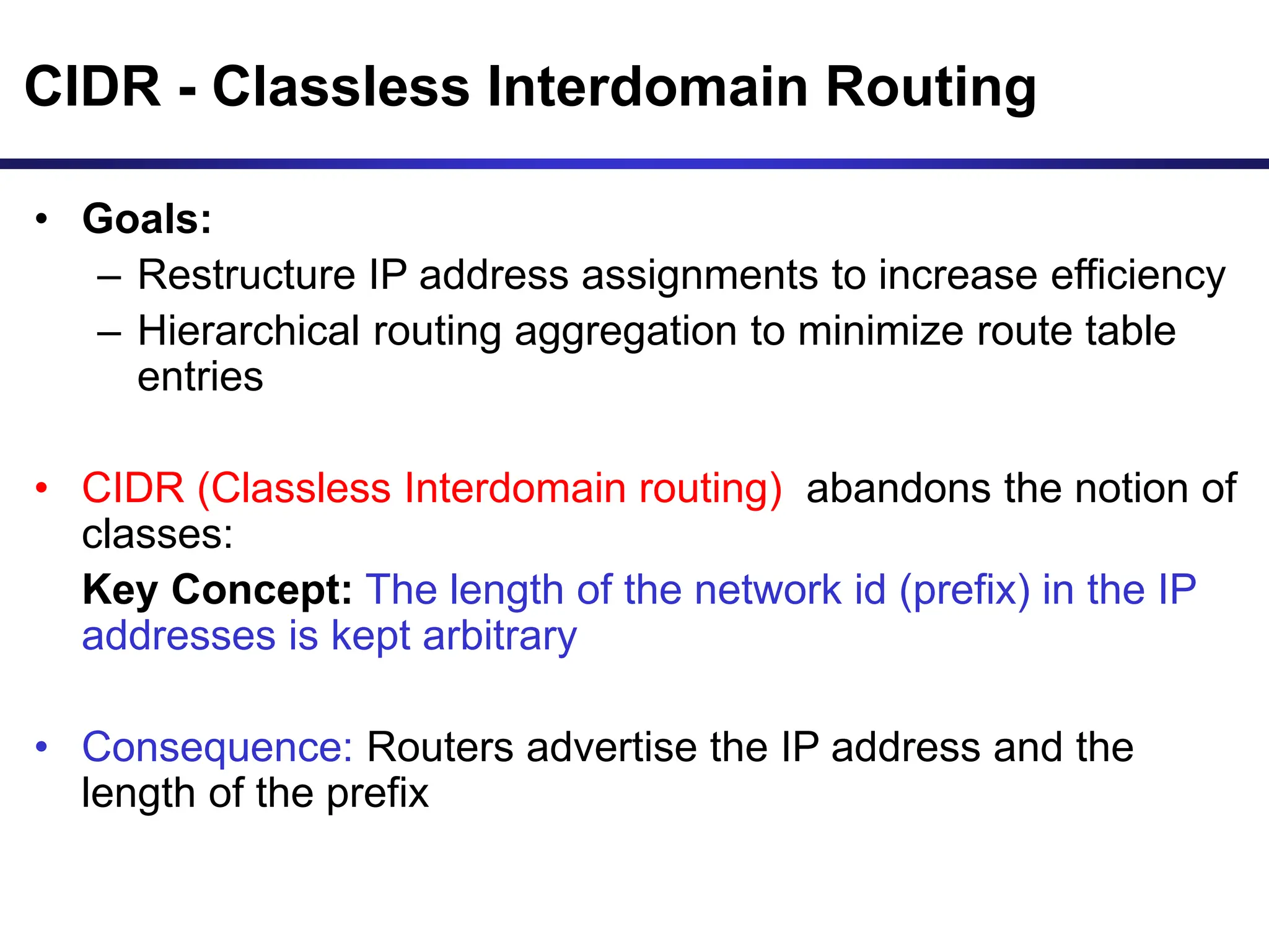
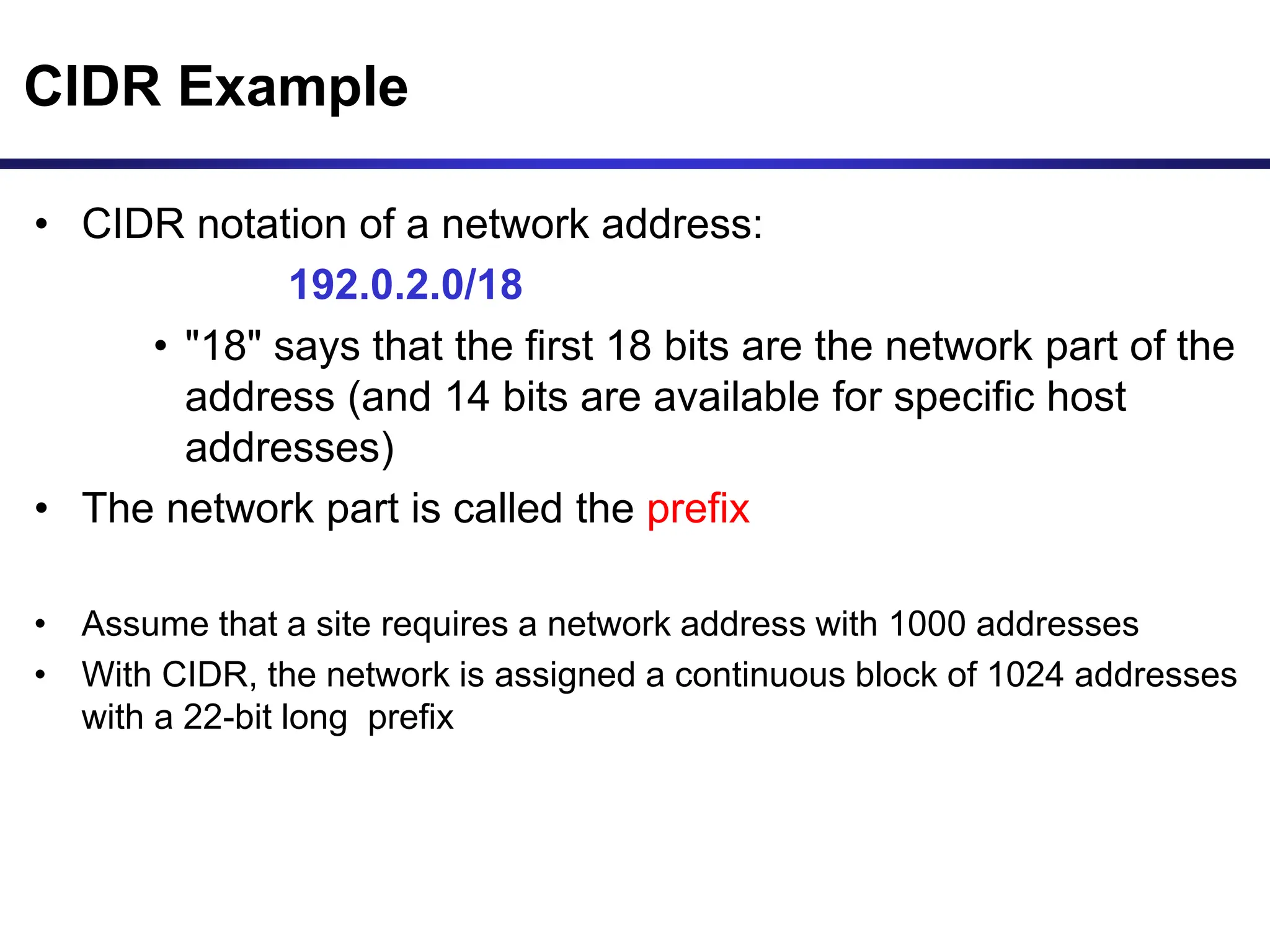
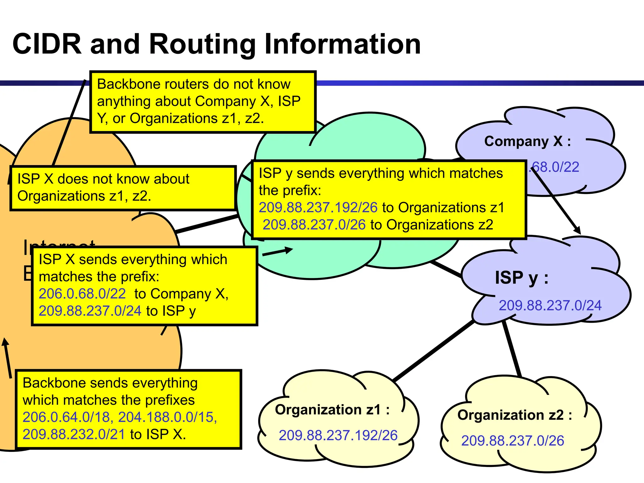
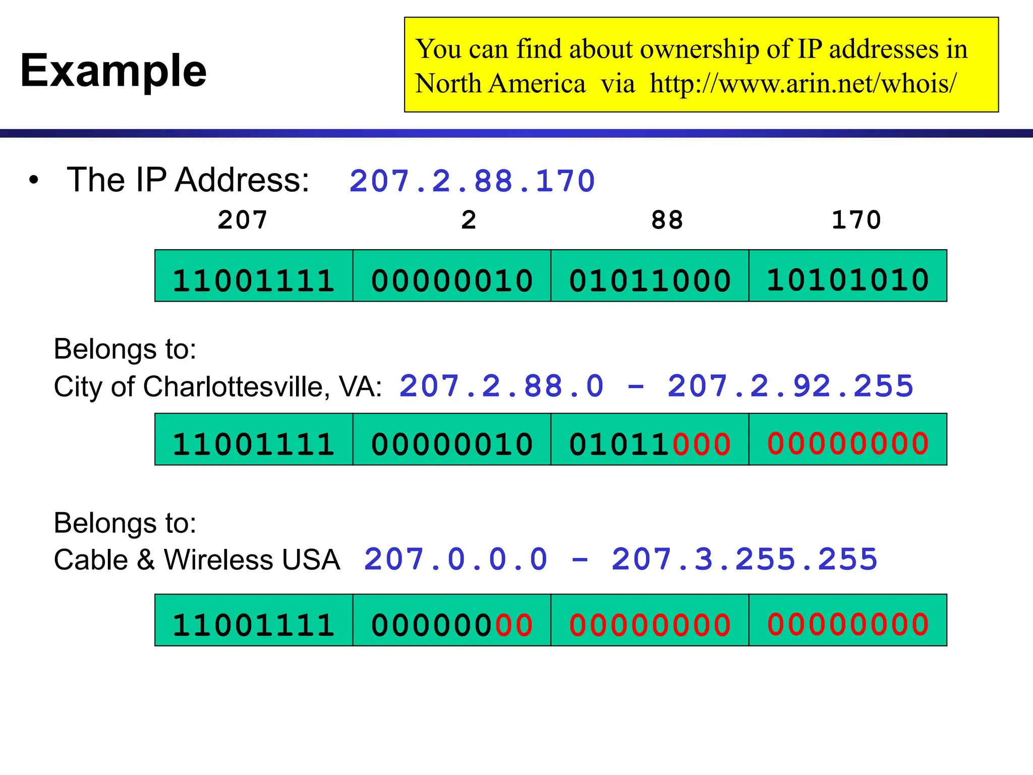
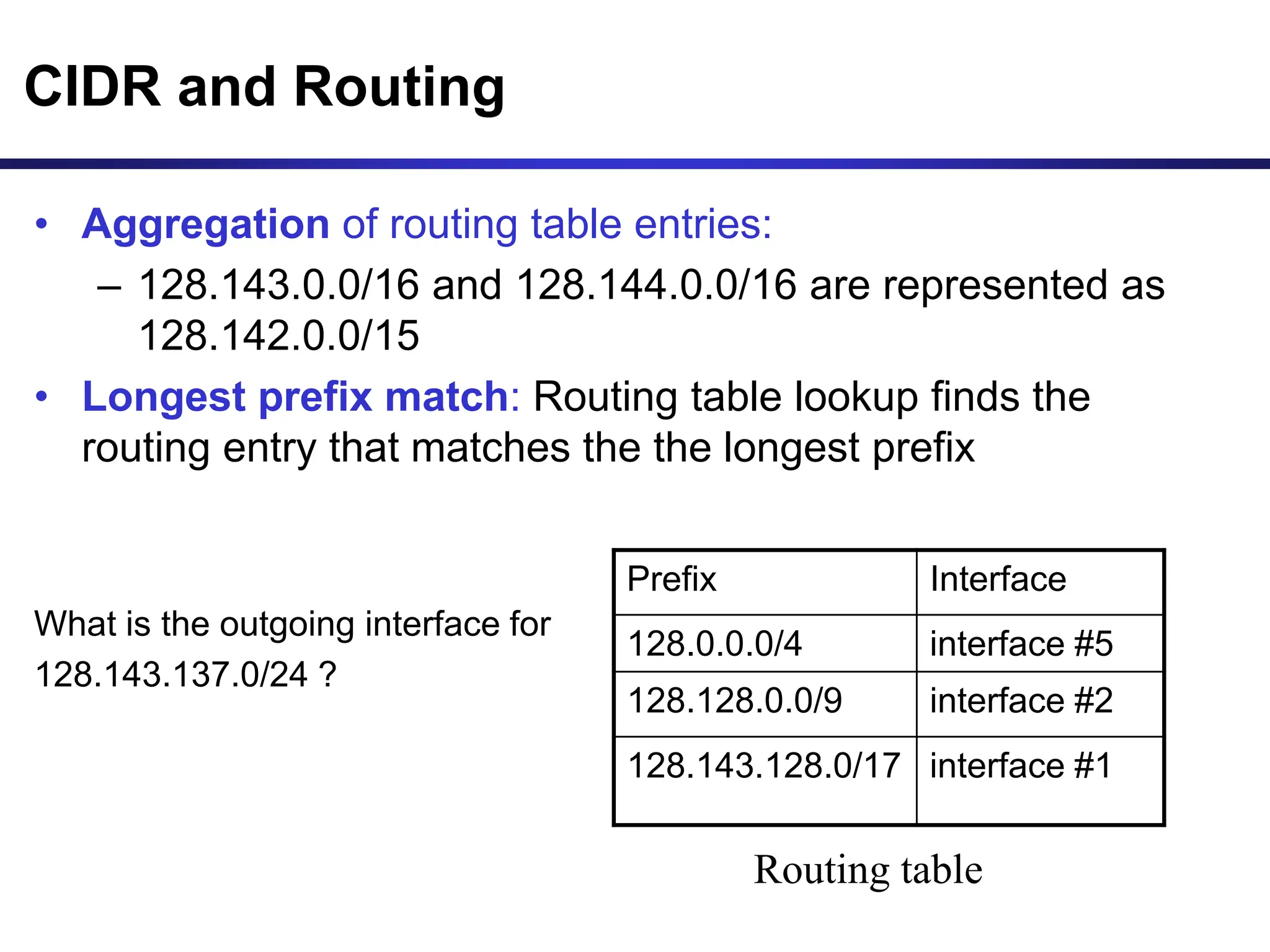
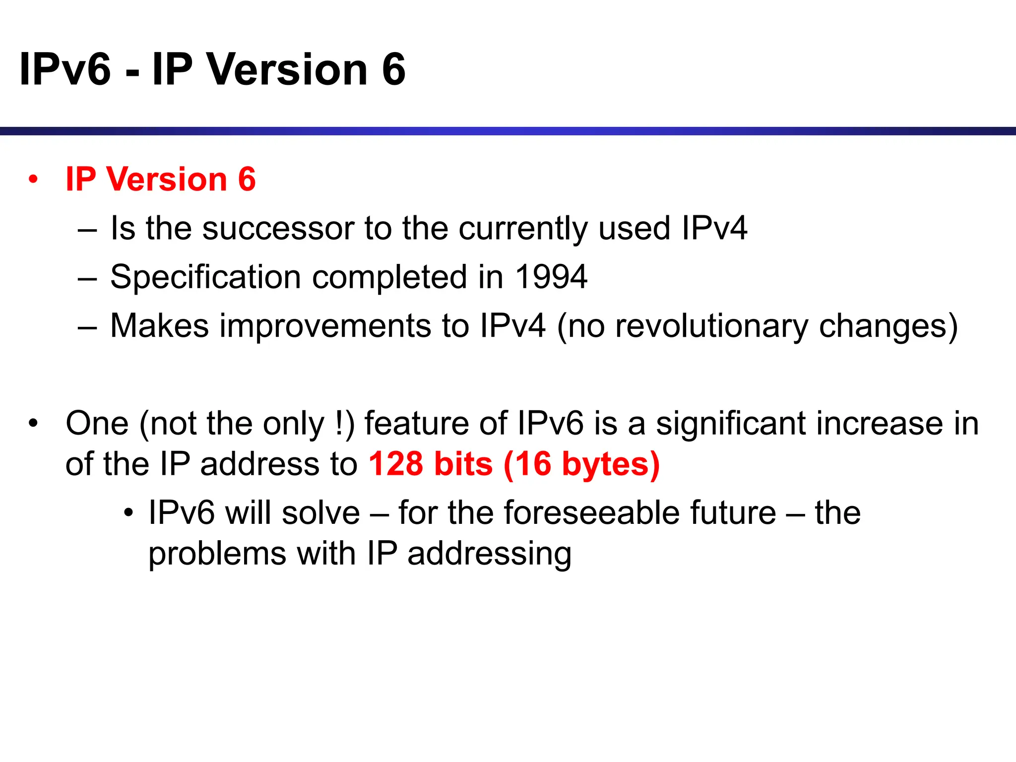
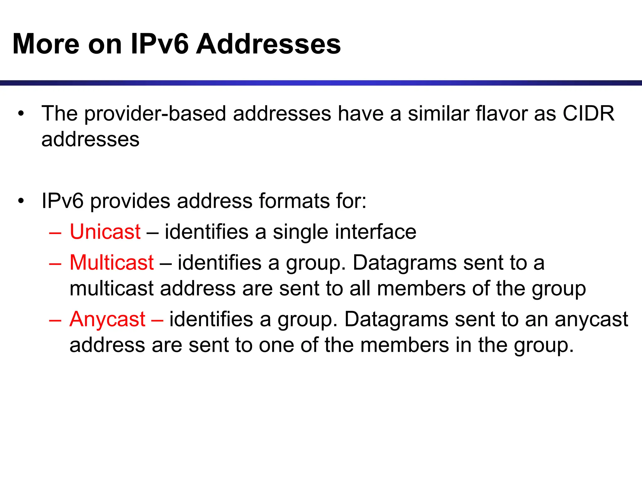
IP Addressing
IP Addresses
• Structure of an IP address
• Classful IP addresses
• Limitations and problems with classful IP addresses
• Subnetting
• CIDR
• IP Version 6 addresses
IP Addresses
Application data
TCP Header
Ethernet Header Ethernet Trailer
Ethernet frame
IP Header
version
(4 bits)
header
length
Type of Service/TOS
(8 bits)
Total Length (in bytes)
(16 bits)
Identification (16 bits)
flags
(3 bits)
Fragment Offset (13 bits)
Source IP address (32 bits)
Destination IP address (32 bits)
TTL Time-to-Live
(8 bits)
Protocol
(8 bits)
Header Checksum (16 bits)
32 bits
IP Addresses
Application data
TCP Header
Ethernet Header Ethernet Trailer
Ethernet frame
IP Header
0x4 0x5 0x00 4410
9d08 0102 00000000000002
128.143.137.144
128.143.71.21
12810 0x06 8bff
32 bits
What is an IP Address?
• An IP address is a unique global address for a network
interface
• An IP address:
- is a 32 bit long identifier
- encodes a network number (network prefix)
and a host number
Dotted Decimal Notation
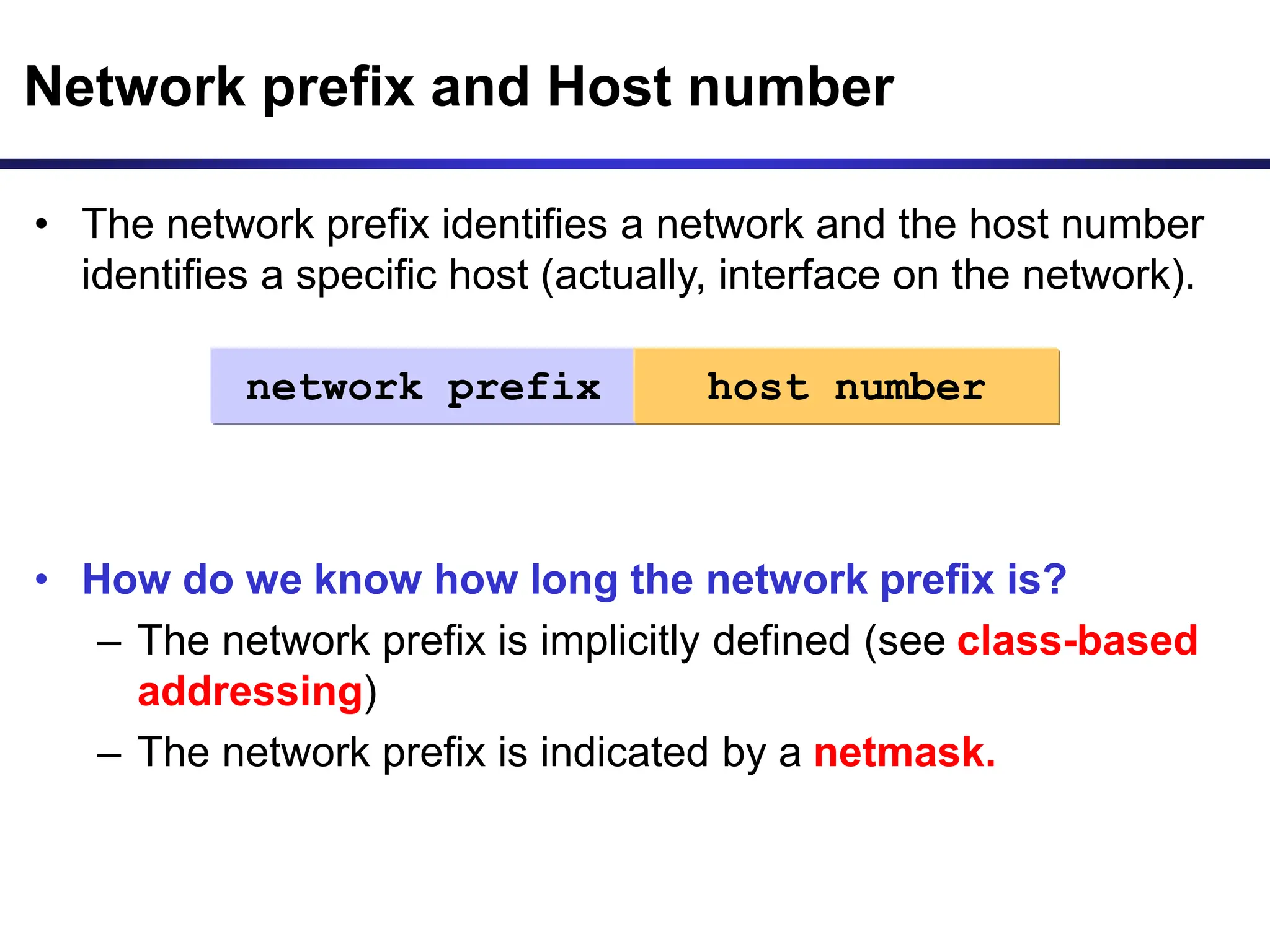
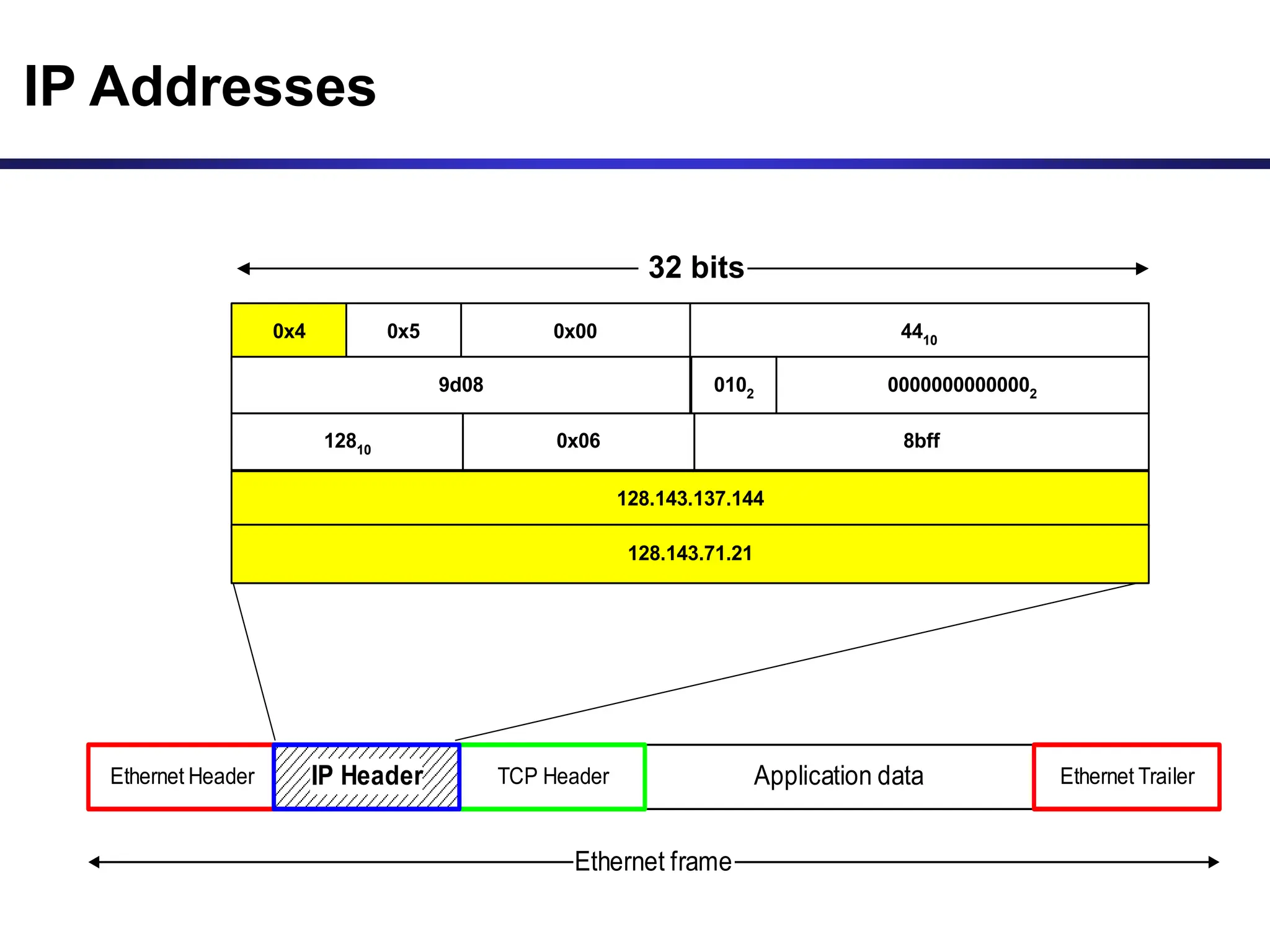
• IP addresses are written in a so-called dotted decimal
notation
• Each byte is identified by a decimal number in the range
[0..255]:
• Example:
10001111
10000000 10001001 10010000
1st Byte
= 128
2nd Byte
= 143
3rd Byte
= 137
4th Byte
= 144
128.143.137.144
• The network prefix identifies a network and the host number
identifies a specific host (actually, interface on the network).
• How do we know how long the network prefix is?
– The network prefix is implicitly defined (see class-based
addressing)
– The network prefix is indicated by a netmask.
Network prefix and Host number
network prefix host number
• Example: ellington.cs.virginia.edu
• Network id is: 128.143.0.0
• Host number is: 137.144
• Network mask is: 255.255.0.0 or ffff0000
• Prefix notation: 128.143.137.144/16
» Network prefix is 16 bits long
Example
128.143 137.144
The old way: Classful IP Adresses
• When Internet addresses were standardized (early 1980s),
the Internet address space was divided up into classes:
– Class A: Network prefix is 8 bits long
– Class B: Network prefix is 16 bits long
– Class C: Network prefix is 24 bits long
• Each IP address contained a key which identifies the class:
– Class A: IP address starts with “0”
– Class B: IP address starts with “10”
– Class C: IP address starts with “110”
The old way: Internet Address Classes
Class C network id host
1
1 0
Network Prefix
24 bits
Host Number
8 bits
bit # 0 1 23 24
2 31
3
Class B 1 network id host
bit # 0 1 15 16
2
Network Prefix
16 bits
Host Number
16 bits
0
31
Class A 0
Network Prefix
8 bits
bit # 0 1 7 8
Host Number
24 bits
31
Class D multicast group id
1
1 1
bit # 0 1 2 31
3
0
4
Class E (reserved for future use)
1
1 1
bit # 0 1 2 31
3
1
4
0
5
The old way: Internet Address Classes
Problems with Classful IP Addresses
• The original classful address scheme had a number
of problems
Problem 1. Too few network addresses for large
networks
– Class A and Class B addresses are gone
Problem 2. Two-layer hierarchy is not appropriate
for large networks with Class A and Class B
addresses.
– Fix #1: Subnetting
Problems with Classful IP Addresses
Problem 3. Inflexible. Assume a company requires 2,000
addresses
– Class A and B addresses are overkill
– Class C address is insufficient (requires 8 Class C
addresses)
– Fix #2: Classless Interdomain Routing (CIDR)
Problems with Classful IP Addresses
Problem 4: Exploding Routing Tables: Routing on the
backbone Internet needs to have an entry for each network
address. In 1993, the size of the routing tables started to
outgrow the capacity of routers.
– Fix #2: Classless Interdomain Routing (CIDR)
Problems with Classful IP Addresses
Problem 5. The Internet is going to outgrow the 32-
bit addresses
– Fix #3: IP Version 6
Subnetting
Subnetting
• Problem: Organizations
have multiple networks
which are independently
managed
– Solution 1: Allocate one or
more Class C address for
each network
• Difficult to manage
• From the outside of the
organization, each network
must be addressable.
– Solution 2: Add another
level of hierarchy to the
IP addressing structure
University Network
Medical
School
Library
Engineering
School
Basic Idea of Subnetting
• Split the host number portion of an IP address into a
subnet number and a (smaller) host number.
• Result is a 3-layer hierarchy
• Then:
• Subnets can be freely assigned within the organization
• Internally, subnets are treated as separate networks
• Subnet structure is not visible outside the organization
network prefix host number
subnet number
network prefix host number
extended network prefix
• Routers and hosts use an extended network prefix (subnet
mask) to identify the start of the host numbers
* There are different ways of subnetting. Commonly used netmasks for university
networks with /16 prefix (Class B) are 255.255.255.0 and 255.255.0.0
Class B network host
16 bits
with
subnetting
host
Subnet
mask
(255.255.255.0)
network subnet
Network Prefix (16 bits)
1
1111111111111111111111100000000
0
10
Extended Network Prefix (24 bits)
Subnet Masks
• Each layer-2 network (Ethernet segment, FDDI segment) is
allocated a subnet address.
128.143.17.0 / 24
128.143.71.0 / 24
128.143.7.0 / 24
128.143.16.0 / 24
128.143.8.0 / 24
128.143.22.0 / 24
128.143.136.0 / 24
Typical Addressing Plan for an Organization that
uses subnetting
128.143.0.0/16
Advantages of Subnetting
• With subnetting, IP addresses use a 3-layer hierarchy:
» Network
» Subnet
» Host
• Improves efficiency of IP addresses by not consuming an
entire Class B or Class C address for each physical network/
• Reduces router complexity. Since external routers do not
know about subnetting, the complexity of routing tables at
external routers is reduced.
• Note: Length of the subnet mask need not be identical at all
subnetworks.
Class A Subnets
In Class A, only the first octet is used as Network identifier and rest of three octets are
used to be assigned to Hosts (i.e. 16777214 Hosts per Network). To make more
subnet in Class A, bits from Host part are borrowed and the subnet mask is changed
accordingly.
Class B Subnets
By default, using Classful Networking, 14 bits are used as Network bits providing (214) 16384 Networks and
(216-2) 65534 Hosts. Class B IP Addresses can be subnetted the same way as Class A addresses, by
borrowing bits from Host bits. Below is given all possible combination of Class B subnetting −
Class C Subnets
Class C IP addresses are normally assigned to a very small size network
because it can only have 254 hosts in a network. Given below is a list of all
possible combination of subnetted Class B IP address −
CIDR - Classless Interdomain Routing
• IP backbone routers have one routing table entry for each
network address:
– With subnetting, a backbone router only needs to know one entry for
each Class A, B, or C networks
– This is acceptable for Class A and Class B networks
• 27 = 128 Class A networks
• 214 = 16,384 Class B networks
– But this is not acceptable for Class C networks
• 221 = 2,097,152 Class C networks
• In 1993, the size of the routing tables started to outgrow the
capacity of routers
• Consequence: The Class-based assignment of IP addresses
had to be abandoned
CIDR - Classless Interdomain Routing
• Goals:
– Restructure IP address assignments to increase efficiency
– Hierarchical routing aggregation to minimize route table
entries
• CIDR (Classless Interdomain routing) abandons the notion of
classes:
Key Concept: The length of the network id (prefix) in the IP
addresses is kept arbitrary
• Consequence: Routers advertise the IP address and the
length of the prefix
CIDR Example
• CIDR notation of a network address:
192.0.2.0/18
• "18" says that the first 18 bits are the network part of the
address (and 14 bits are available for specific host
addresses)
• The network part is called the prefix
• Assume that a site requires a network address with 1000 addresses
• With CIDR, the network is assigned a continuous block of 1024 addresses
with a 22-bit long prefix
CIDR: Prefix Size vs. Network Size
CIDR Block Prefix # of Host Addresses
/27 32 hosts
/26 64 hosts
/25 128 hosts
/24 256 hosts
/23 512 hosts
/22 1,024 hosts
/21 2,048 hosts
/20 4,096 hosts
/19 8,192 hosts
/18 16,384 hosts
/17 32,768 hosts
/16 65,536 hosts
/15 131,072 hosts
/14 262,144 hosts
/13 524,288 hosts
CIDR and Address assignments
• CIDR (Classless Inter-Domain Routing) is a method of assigning IP
addresses that improves the efficiency of address distribution and
replaces the previous system based on Class A, Class B and Class C
networks.
Example:
• Assume that an ISP owns the address block 206.0.64.0/18, which
represents 16,384 (214) IP addresses
• Suppose a client requires 800 host addresses
• With classful addresses: need to assign a class B address (and
waste ~64,700 addresses) or four individual Class Cs (and introducing 4
new routes into the global Internet routing tables)
• With CIDR: Assign a /22 block, e.g., 206.0.68.0/22, and allocated a
block of 1,024 (210) IP addresses.
**This new system empowers organizations to only get the amount of IP
addresses they need in their networks, without wasting unused space.
CIDR and Routing Information
206.0.64.0/18
204.188.0.0/15
209.88.232.0/21
Internet
Backbone
ISP X owns:
Company X :
206.0.68.0/22
ISP y :
209.88.237.0/24
Organization z1 :
209.88.237.192/26
Organization z2 :
209.88.237.0/26
CIDR and Routing Information
206.0.64.0/18
204.188.0.0/15
209.88.232.0/21
Internet
Backbone
ISP X owns:
Company X :
206.0.68.0/22
ISP y :
209.88.237.0/24
Organization z1 :
209.88.237.192/26
Organization z2 :
209.88.237.0/26
Backbone sends everything
which matches the prefixes
206.0.64.0/18, 204.188.0.0/15,
209.88.232.0/21 to ISP X.
ISP X sends everything which
matches the prefix:
206.0.68.0/22 to Company X,
209.88.237.0/24 to ISP y
Backbone routers do not know
anything about Company X, ISP
Y, or Organizations z1, z2.
ISP X does not know about
Organizations z1, z2.
ISP y sends everything which matches
the prefix:
209.88.237.192/26 to Organizations z1
209.88.237.0/26 to Organizations z2
Example
Belongs to:
Cable & Wireless USA 207.0.0.0 - 207.3.255.255
11001111 00000010
207 2
01011000
88
10101010
170
11001111 00000010 01011000 00000000
Belongs to:
City of Charlottesville, VA: 207.2.88.0 - 207.2.92.255
11001111 00000000 00000000 00000000
You can find about ownership of IP addresses in
North America via http://www.arin.net/whois/
• The IP Address: 207.2.88.170
CIDR and Routing
• Aggregation of routing table entries:
– 128.143.0.0/16 and 128.144.0.0/16 are represented as
128.142.0.0/15
• Longest prefix match: Routing table lookup finds the
routing entry that matches the the longest prefix
What is the outgoing interface for
128.143.137.0/24 ?
Prefix Interface
128.0.0.0/4 interface #5
128.128.0.0/9 interface #2
128.143.128.0/17 interface #1
Routing table
IPv6 - IP Version 6
• IP Version 6
– Is the successor to the currently used IPv4
– Specification completed in 1994
– Makes improvements to IPv4 (no revolutionary changes)
• One (not the only !) feature of IPv6 is a significant increase in
of the IP address to 128 bits (16 bytes)
• IPv6 will solve – for the foreseeable future – the
problems with IP addressing
IPv6 Header
Application data
TCP Header
Ethernet Header Ethernet Trailer
Ethernet frame
IPv6 Header
version
(4 bits)
Traffic Class
(8 bits)
Flow Label
(24 bits)
Payload Length (16 bits)
Next Header
(8 bits)
Hop Limits (8 bits)
Source IP address (128 bits)
32 bits
Destination IP address (128 bits)
IPv6 vs. IPv4: Address Comparison
• IPv4 has a maximum of
232  4 billion addresses
• IPv6 has a maximum of
2128 = (232)4  4 billion x 4 billion x 4 billion x 4 billion
addresses
Notation of IPv6 addresses
• Convention: The 128-bit IPv6 address is written as eight 16-
bit integers (using hexadecimal digits for each integer)
CEDF:BP76:3245:4464:FACE:2E50:3025:DF12
• Short notation:
• Abbreviations of leading zeroes:
CEDF:BP76:0000:0000:009E:0000:3025:DF12
 CEDF:BP76:0:0:9E :0:3025:DF12
• “:0000:0000:0000” can be written as “::”
CEDF:BP76:0:0:FACE:0:3025:DF12  CEDF:BP76::FACE:0:3025:DF12
• IPv6 addresses derived from IPv4 addresses have 96 leading zero bits.
Convention allows to use IPv4 notation for the last 32 bits.
::80:8F:89:90  ::128.143.137.144
IPv6 Provider-Based Addresses
• The first IPv6 addresses will be allocated to a provider-based
plan
• Type: Set to “010” for provider-based addresses
• Registry: identifies the agency that registered the address
The following fields have a variable length (recommeded length in “()”)
• Provider: Id of Internet access provider (16 bits)
• Subscriber: Id of the organization at provider (24 bits)
• Subnetwork: Id of subnet within organization (32 bits)
• Interface: identifies an interface at a node (48 bits)
Registry
ID
Provider
ID
010
Subscriber
ID
Interface
ID
Subnetwork
ID
More on IPv6 Addresses
• The provider-based addresses have a similar flavor as CIDR
addresses
• IPv6 provides address formats for:
– Unicast – identifies a single interface
– Multicast – identifies a group. Datagrams sent to a
multicast address are sent to all members of the group
– Anycast – identifies a group. Datagrams sent to an anycast
address are sent to one of the members in the group.

this is a presentationon ip and cidr.ppt

  • 1.
  • 2.
    IP Addresses • Structureof an IP address • Classful IP addresses • Limitations and problems with classful IP addresses • Subnetting • CIDR • IP Version 6 addresses
  • 3.
    IP Addresses Application data TCPHeader Ethernet Header Ethernet Trailer Ethernet frame IP Header version (4 bits) header length Type of Service/TOS (8 bits) Total Length (in bytes) (16 bits) Identification (16 bits) flags (3 bits) Fragment Offset (13 bits) Source IP address (32 bits) Destination IP address (32 bits) TTL Time-to-Live (8 bits) Protocol (8 bits) Header Checksum (16 bits) 32 bits
  • 4.
    IP Addresses Application data TCPHeader Ethernet Header Ethernet Trailer Ethernet frame IP Header 0x4 0x5 0x00 4410 9d08 0102 00000000000002 128.143.137.144 128.143.71.21 12810 0x06 8bff 32 bits
  • 5.
    What is anIP Address? • An IP address is a unique global address for a network interface • An IP address: - is a 32 bit long identifier - encodes a network number (network prefix) and a host number
  • 6.
    Dotted Decimal Notation •IP addresses are written in a so-called dotted decimal notation • Each byte is identified by a decimal number in the range [0..255]: • Example: 10001111 10000000 10001001 10010000 1st Byte = 128 2nd Byte = 143 3rd Byte = 137 4th Byte = 144 128.143.137.144
  • 7.
    • The networkprefix identifies a network and the host number identifies a specific host (actually, interface on the network). • How do we know how long the network prefix is? – The network prefix is implicitly defined (see class-based addressing) – The network prefix is indicated by a netmask. Network prefix and Host number network prefix host number
  • 8.
    • Example: ellington.cs.virginia.edu •Network id is: 128.143.0.0 • Host number is: 137.144 • Network mask is: 255.255.0.0 or ffff0000 • Prefix notation: 128.143.137.144/16 » Network prefix is 16 bits long Example 128.143 137.144
  • 9.
    The old way:Classful IP Adresses • When Internet addresses were standardized (early 1980s), the Internet address space was divided up into classes: – Class A: Network prefix is 8 bits long – Class B: Network prefix is 16 bits long – Class C: Network prefix is 24 bits long • Each IP address contained a key which identifies the class: – Class A: IP address starts with “0” – Class B: IP address starts with “10” – Class C: IP address starts with “110”
  • 10.
    The old way:Internet Address Classes Class C network id host 1 1 0 Network Prefix 24 bits Host Number 8 bits bit # 0 1 23 24 2 31 3 Class B 1 network id host bit # 0 1 15 16 2 Network Prefix 16 bits Host Number 16 bits 0 31 Class A 0 Network Prefix 8 bits bit # 0 1 7 8 Host Number 24 bits 31
  • 11.
    Class D multicastgroup id 1 1 1 bit # 0 1 2 31 3 0 4 Class E (reserved for future use) 1 1 1 bit # 0 1 2 31 3 1 4 0 5 The old way: Internet Address Classes
  • 12.
    Problems with ClassfulIP Addresses • The original classful address scheme had a number of problems Problem 1. Too few network addresses for large networks – Class A and Class B addresses are gone Problem 2. Two-layer hierarchy is not appropriate for large networks with Class A and Class B addresses. – Fix #1: Subnetting
  • 13.
    Problems with ClassfulIP Addresses Problem 3. Inflexible. Assume a company requires 2,000 addresses – Class A and B addresses are overkill – Class C address is insufficient (requires 8 Class C addresses) – Fix #2: Classless Interdomain Routing (CIDR)
  • 14.
    Problems with ClassfulIP Addresses Problem 4: Exploding Routing Tables: Routing on the backbone Internet needs to have an entry for each network address. In 1993, the size of the routing tables started to outgrow the capacity of routers. – Fix #2: Classless Interdomain Routing (CIDR)
  • 15.
    Problems with ClassfulIP Addresses Problem 5. The Internet is going to outgrow the 32- bit addresses – Fix #3: IP Version 6
  • 16.
    Subnetting Subnetting • Problem: Organizations havemultiple networks which are independently managed – Solution 1: Allocate one or more Class C address for each network • Difficult to manage • From the outside of the organization, each network must be addressable. – Solution 2: Add another level of hierarchy to the IP addressing structure University Network Medical School Library Engineering School
  • 17.
    Basic Idea ofSubnetting • Split the host number portion of an IP address into a subnet number and a (smaller) host number. • Result is a 3-layer hierarchy • Then: • Subnets can be freely assigned within the organization • Internally, subnets are treated as separate networks • Subnet structure is not visible outside the organization network prefix host number subnet number network prefix host number extended network prefix
  • 18.
    • Routers andhosts use an extended network prefix (subnet mask) to identify the start of the host numbers * There are different ways of subnetting. Commonly used netmasks for university networks with /16 prefix (Class B) are 255.255.255.0 and 255.255.0.0 Class B network host 16 bits with subnetting host Subnet mask (255.255.255.0) network subnet Network Prefix (16 bits) 1 1111111111111111111111100000000 0 10 Extended Network Prefix (24 bits) Subnet Masks
  • 19.
    • Each layer-2network (Ethernet segment, FDDI segment) is allocated a subnet address. 128.143.17.0 / 24 128.143.71.0 / 24 128.143.7.0 / 24 128.143.16.0 / 24 128.143.8.0 / 24 128.143.22.0 / 24 128.143.136.0 / 24 Typical Addressing Plan for an Organization that uses subnetting 128.143.0.0/16
  • 20.
    Advantages of Subnetting •With subnetting, IP addresses use a 3-layer hierarchy: » Network » Subnet » Host • Improves efficiency of IP addresses by not consuming an entire Class B or Class C address for each physical network/ • Reduces router complexity. Since external routers do not know about subnetting, the complexity of routing tables at external routers is reduced. • Note: Length of the subnet mask need not be identical at all subnetworks.
  • 21.
    Class A Subnets InClass A, only the first octet is used as Network identifier and rest of three octets are used to be assigned to Hosts (i.e. 16777214 Hosts per Network). To make more subnet in Class A, bits from Host part are borrowed and the subnet mask is changed accordingly.
  • 22.
    Class B Subnets Bydefault, using Classful Networking, 14 bits are used as Network bits providing (214) 16384 Networks and (216-2) 65534 Hosts. Class B IP Addresses can be subnetted the same way as Class A addresses, by borrowing bits from Host bits. Below is given all possible combination of Class B subnetting −
  • 23.
    Class C Subnets ClassC IP addresses are normally assigned to a very small size network because it can only have 254 hosts in a network. Given below is a list of all possible combination of subnetted Class B IP address −
  • 24.
    CIDR - ClasslessInterdomain Routing • IP backbone routers have one routing table entry for each network address: – With subnetting, a backbone router only needs to know one entry for each Class A, B, or C networks – This is acceptable for Class A and Class B networks • 27 = 128 Class A networks • 214 = 16,384 Class B networks – But this is not acceptable for Class C networks • 221 = 2,097,152 Class C networks • In 1993, the size of the routing tables started to outgrow the capacity of routers • Consequence: The Class-based assignment of IP addresses had to be abandoned
  • 25.
    CIDR - ClasslessInterdomain Routing • Goals: – Restructure IP address assignments to increase efficiency – Hierarchical routing aggregation to minimize route table entries • CIDR (Classless Interdomain routing) abandons the notion of classes: Key Concept: The length of the network id (prefix) in the IP addresses is kept arbitrary • Consequence: Routers advertise the IP address and the length of the prefix
  • 26.
    CIDR Example • CIDRnotation of a network address: 192.0.2.0/18 • "18" says that the first 18 bits are the network part of the address (and 14 bits are available for specific host addresses) • The network part is called the prefix • Assume that a site requires a network address with 1000 addresses • With CIDR, the network is assigned a continuous block of 1024 addresses with a 22-bit long prefix
  • 27.
    CIDR: Prefix Sizevs. Network Size CIDR Block Prefix # of Host Addresses /27 32 hosts /26 64 hosts /25 128 hosts /24 256 hosts /23 512 hosts /22 1,024 hosts /21 2,048 hosts /20 4,096 hosts /19 8,192 hosts /18 16,384 hosts /17 32,768 hosts /16 65,536 hosts /15 131,072 hosts /14 262,144 hosts /13 524,288 hosts
  • 29.
    CIDR and Addressassignments • CIDR (Classless Inter-Domain Routing) is a method of assigning IP addresses that improves the efficiency of address distribution and replaces the previous system based on Class A, Class B and Class C networks. Example: • Assume that an ISP owns the address block 206.0.64.0/18, which represents 16,384 (214) IP addresses • Suppose a client requires 800 host addresses • With classful addresses: need to assign a class B address (and waste ~64,700 addresses) or four individual Class Cs (and introducing 4 new routes into the global Internet routing tables) • With CIDR: Assign a /22 block, e.g., 206.0.68.0/22, and allocated a block of 1,024 (210) IP addresses. **This new system empowers organizations to only get the amount of IP addresses they need in their networks, without wasting unused space.
  • 30.
    CIDR and RoutingInformation 206.0.64.0/18 204.188.0.0/15 209.88.232.0/21 Internet Backbone ISP X owns: Company X : 206.0.68.0/22 ISP y : 209.88.237.0/24 Organization z1 : 209.88.237.192/26 Organization z2 : 209.88.237.0/26
  • 31.
    CIDR and RoutingInformation 206.0.64.0/18 204.188.0.0/15 209.88.232.0/21 Internet Backbone ISP X owns: Company X : 206.0.68.0/22 ISP y : 209.88.237.0/24 Organization z1 : 209.88.237.192/26 Organization z2 : 209.88.237.0/26 Backbone sends everything which matches the prefixes 206.0.64.0/18, 204.188.0.0/15, 209.88.232.0/21 to ISP X. ISP X sends everything which matches the prefix: 206.0.68.0/22 to Company X, 209.88.237.0/24 to ISP y Backbone routers do not know anything about Company X, ISP Y, or Organizations z1, z2. ISP X does not know about Organizations z1, z2. ISP y sends everything which matches the prefix: 209.88.237.192/26 to Organizations z1 209.88.237.0/26 to Organizations z2
  • 32.
    Example Belongs to: Cable &Wireless USA 207.0.0.0 - 207.3.255.255 11001111 00000010 207 2 01011000 88 10101010 170 11001111 00000010 01011000 00000000 Belongs to: City of Charlottesville, VA: 207.2.88.0 - 207.2.92.255 11001111 00000000 00000000 00000000 You can find about ownership of IP addresses in North America via http://www.arin.net/whois/ • The IP Address: 207.2.88.170
  • 33.
    CIDR and Routing •Aggregation of routing table entries: – 128.143.0.0/16 and 128.144.0.0/16 are represented as 128.142.0.0/15 • Longest prefix match: Routing table lookup finds the routing entry that matches the the longest prefix What is the outgoing interface for 128.143.137.0/24 ? Prefix Interface 128.0.0.0/4 interface #5 128.128.0.0/9 interface #2 128.143.128.0/17 interface #1 Routing table
  • 34.
    IPv6 - IPVersion 6 • IP Version 6 – Is the successor to the currently used IPv4 – Specification completed in 1994 – Makes improvements to IPv4 (no revolutionary changes) • One (not the only !) feature of IPv6 is a significant increase in of the IP address to 128 bits (16 bytes) • IPv6 will solve – for the foreseeable future – the problems with IP addressing
  • 35.
    IPv6 Header Application data TCPHeader Ethernet Header Ethernet Trailer Ethernet frame IPv6 Header version (4 bits) Traffic Class (8 bits) Flow Label (24 bits) Payload Length (16 bits) Next Header (8 bits) Hop Limits (8 bits) Source IP address (128 bits) 32 bits Destination IP address (128 bits)
  • 36.
    IPv6 vs. IPv4:Address Comparison • IPv4 has a maximum of 232  4 billion addresses • IPv6 has a maximum of 2128 = (232)4  4 billion x 4 billion x 4 billion x 4 billion addresses
  • 37.
    Notation of IPv6addresses • Convention: The 128-bit IPv6 address is written as eight 16- bit integers (using hexadecimal digits for each integer) CEDF:BP76:3245:4464:FACE:2E50:3025:DF12 • Short notation: • Abbreviations of leading zeroes: CEDF:BP76:0000:0000:009E:0000:3025:DF12  CEDF:BP76:0:0:9E :0:3025:DF12 • “:0000:0000:0000” can be written as “::” CEDF:BP76:0:0:FACE:0:3025:DF12  CEDF:BP76::FACE:0:3025:DF12 • IPv6 addresses derived from IPv4 addresses have 96 leading zero bits. Convention allows to use IPv4 notation for the last 32 bits. ::80:8F:89:90  ::128.143.137.144
  • 38.
    IPv6 Provider-Based Addresses •The first IPv6 addresses will be allocated to a provider-based plan • Type: Set to “010” for provider-based addresses • Registry: identifies the agency that registered the address The following fields have a variable length (recommeded length in “()”) • Provider: Id of Internet access provider (16 bits) • Subscriber: Id of the organization at provider (24 bits) • Subnetwork: Id of subnet within organization (32 bits) • Interface: identifies an interface at a node (48 bits) Registry ID Provider ID 010 Subscriber ID Interface ID Subnetwork ID
  • 39.
    More on IPv6Addresses • The provider-based addresses have a similar flavor as CIDR addresses • IPv6 provides address formats for: – Unicast – identifies a single interface – Multicast – identifies a group. Datagrams sent to a multicast address are sent to all members of the group – Anycast – identifies a group. Datagrams sent to an anycast address are sent to one of the members in the group.