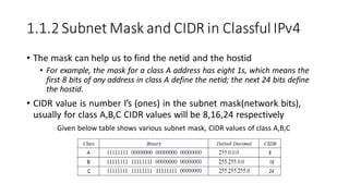
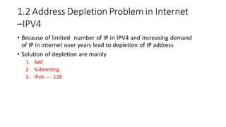
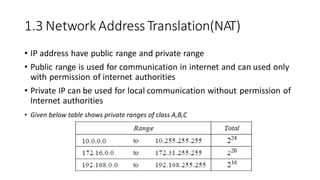
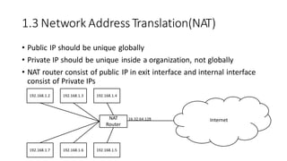
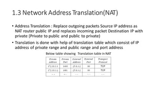
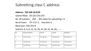
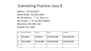
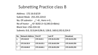
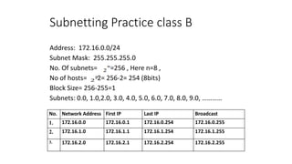
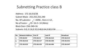
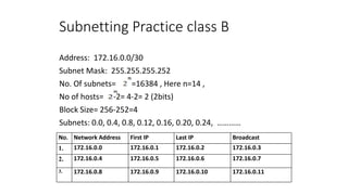
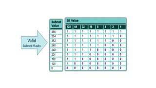
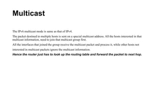
2. Needfor Network layer
• The network layer is responsible for host-to-host delivery
• Routing the packets through the routers or switches
• The network layer at the source is responsible for creating a packet
from the data coming from another protocol
• The network layer is responsible for checking its routing table to find
the routing information
3.
4.
5. 1 IP Address v4
• An IPv4 address is 32 bits long
• The IPv4 addresses are unique and universal
• IPv4 uses 32-bit addresses, which means that the address space is
232 or 4,294,967,296(Maximum available theoretically)
• IPv4 have 2 types of notations:
1. Doted decimal
Denoted in decimal format each byte is separated by dot eg: 117.149.29.2
Mostly used by human configurations
2. Binary notation
In binary format eg: 01110101 10010101 00011101 00000010
Mostly used by devices for processing
6. 1.1 IPv4 Classes(Classfull Address)
• The address space is divided into five classes: A, B, C, D, and E
•Division is based on the first byte in doted decimal format
Class A
Range of first octet or byte is between 0 to 127
First byte is network and last 3 bytes are Host (N.H.H.H)
First bit always will be zero (0xxxxxxx.xxxxxxxx. xxxxxxxx.xxxxxxxx)
Used for unicasting, valid host IP
Class B
Range of first octet or byte is between 128 to 191
First 2 bytes is network and last 2 byte are Host (N.N.H.H)
First bit always will be zero (10xxxxxxx.xxxxxxxx.xxxxxxxx. xxxxxxxx)
Used for unicasting, valid host IP
10.1.2.31
7. 1.1 IPv4 Classes
Class C
Range of first octet or byte is between 192 to 223
First 3 bytes is network and last byte are Host (N.N.N.H)
First bit always will be zero (110xxxxx. xxxxxxxx. xxxxxxxx. xxxxxxxx)
Used for unicasting, valid host IP
Class D
Range of first octet or byte is between 224 to 239
First 2 bytes is network and last 2 byte are Host (N.N.H.H)
First bit always will be zero (1110xxxx. xxxxxxxx. xxxxxxxx. xxxxxxxx)
Used for Multicasting, Special Address
Class E
Range of first octet or byte is between 240 to 255
First 2 bytes is network and last 2 byte are Host (N.N.H.H)
First bit always will be zero (1111xxxx. xxxxxxxx. xxxxxxxx. xxxxxxxx)
Used for research purpose
245.21.45.24
8.
9. 1.1.1 Netid & Host ID
• Class A :- first byte netid and last 3 bytes hostid (N.H.H.H)
• Class B :- first 2 bytes netid and last 2 bytes hostid (N.N.H.H)
• Class C :- first 3 bytes netid and last byte hostid (N.N.N.H)
• Subnet mask helps to identify netid and hostid
• CIDR value is total number of network bits in subnetmask
10. 1.1.2 Subnet Mask and CIDR in Classful IPv4
• The mask can help us to find the netid and the hostid
• For example, the mask for a class A address has eight 1s, which means the
first 8 bits of any address in class A define the netid; the next 24 bits define
the hostid.
• CIDR value is number I’s (ones) in the subnet mask(network bits),
usually for class A,B,C CIDR values will be 8,16,24 respectively
Given below table shows various subnet mask, CIDR values of class A,B,C
11. 1.2 Address Depletion Problemin Internet
–IPV4
• Because of limited number of IP in IPV4 and increasing demand
of IP in internet over years lead to depletion of IP address
• Solution of depletion are mainly
1. NAT
2. Subnetting
3. IPv6 ---- 128
12. 1.3 Network AddressTranslation(NAT)
• IP address have public range and private range
• Public range is used for communication in internet and can used only
with permission of internet authorities
• Private IP can be used for local communication without permission of
Internet authorities
• Given below table shows private ranges of class A,B,C
13. 1.3 Network AddressTranslation(NAT)
• Public IP should be unique globally
• Private IP should be unique inside a organization, not globally
• NAT router consist of public IP in exit interface and internal interface
consist of Private IPs
192.168.1.4
192.168.1.5
192.168.1.2 192.168.1.3
192.168.1.6
192.168.1.7
Internet
NAT
Router
16.32.64.128
14. 1.3 Network AddressTranslation(NAT)
• Address Translation : Replace outgoing packets Source IP address as
NAT router public IP and replaces incoming packet Destination IP with
private (Private to public and public to private)
• Translation is done with help of translation table which consist of IP
address of private range and public range and port address
Below table showing Translation table in NAT
15. 1.4.1 Subnetting
• Subnetting means creating subnetwork
• Subnetting means increasing networks bits(i.e. 1s) in subnet mask
• If network bit is increased host bits will be decreased, so number of
host will be decreased
• A Class A network have 8 bits for network (224IP address available) if
you wanted smaller block IP from class A increase the network bits /
decreasing host bits
16. 1.4.2. Supernetting
• Supernetting means creating bigger network from smaller one
• Supernetting means decreasing networks bits(i.e. 1s) in subnet mask
• If network bit is decreased host bits will be increased, so number of
host will be decreased
• A Class C network have 24 bits for network (28IP address available) if
you wanted bigger block IP from class C decrease the network bits /
increasing host bits
• Supernetting just opposite of subnetting
17. Subnetting
• To break up a giant network into a bunch of smaller ones is
called subnetting.
• Creating subnetworks is essentially the act of taking bits from
the host portion of the address and reserving them to define
the subnet address instead. It will result in fewer bits being
available for defining your hosts.
To create a subnet, fulfil these three steps:
1. Determine the number of required network IDs:
2. Determine the number of required host IDs per subnet:
3. Based on the above requirements, create the following:
- A unique subnet mask for your entire network
-A unique subnet ID for each physical segment
-A range of host IDs for each subnet
18. Subnet Masks
A subnet mask is a 32-bit value that allows the device that’s
receiving IP packets to distinguish the network ID portion
from the host ID portion of the IP address. This 32-bit subnet
mask is composed of 1s and 0s, where the 1s represent the
positions that refer to the network subnet addresses.
20. Decimal values in a mask and their binary equivalents
Decimal Binary
0 00000000
128 10000000
192 11000000
224 11100000
240 11110000
248 11111000
252 11111100
254 11111110
255 11111111
21. Classless Inter-Domain Routing (CIDR)
It’s basically the method that Internet service providers (ISPs) use to allocate a number
of addresses to a companies. It uses the slash notation that represents the number of
1s in the subnet mask.
192.168.10.32/28. This is telling you what your subnet mask is. The slash notation (/)
means how many bits are turned on (1s).
Subnet Mask CIDR representation
• 255.0.0.0 /8
• 255.255.0.0 /16
• 255.255.128.0 /17
• 255.255.192.0 /18
• 255.255.224.0 /19
• 255.255.240.0 /20
• 255.255.248.0 /21
• 255.255.252.0 /22
• 255.255.254.0 /23
• 255.255.255.0 /24
22. Subnetting Class C Addresses
In a Class C address, only 8 bits are available for defining the
hosts. Remember that subnet bits start at the left and move to
the right, without skipping bits. This means that the only Class C
subnet masks can be the following:
Binary Decimal CIDR
• 00000000= 0 /24
• 10000000= 128 /25
• 11000000= 192 /26
• 11100000= 224 /27
• 11110000= 240 /28
• 11111000= 248 /29
• 11111100= 252 /30
23. Subnetting Formulas
• How many subnets? 2x = number of subnets. x is the
number of masked bits.
• How many hosts per subnet? 2y – 2 = number of hosts
per subnet. y is the number of unmasked bits, or the
0s.
• What are the valid subnets? 256 – subnet mask =
block size, or increment number.
24. Subnetting class C address
1. Address: 192.168.10.0/25
Subnet Mask: 255.255.255.128
No. Of subnets= , Here n is bits for subnetting which is 1,
= 2
No of hosts= -2= 128-2= 126
Block Size= 256-128= 128, Subnets: 0,128
No. Network Address First IP Last IP Broadcast
1. 192.168.10.0 192.168.10.1 192.168.10.126 192.168.10.127
2. 192.168.10.128 192.168.10.129 192.168.10.254 192.168.10.255
25. Subnetting class C address
Address: 192.168.10.0/28
Subnet Mask: 255.255.255.240
No. Of subnets= =16 , Bits taken for subnetting = 4
No of hosts= -2= 16-2= 14, Host bits=4
Block Size= 256-240=16
Subnets: 0, 16, 32, 48, 64, 80, 96, …
No. Network Address First IP Last IP Broadcast
1. 192.168.10.0 192.168.10.1 192.168.10.14 192.168.10.15
2. 192.168.10.16 192.168.10.17 192.168.10.30 192.168.10.31
3. 192.168.10.32 192.168.10.33 192.168.10.46 192.168.10.47
26. Subnetting class C address
Address: 192.168.10.0/29
Subnet Mask: 255.255.255.248
No. Of subnets= =32 , Bits taken for subnetting = 5
No of hosts= -2= 8-2= 6, Host bits=3
Block Size= 256-248=8
Subnets: 0, 8,16,24, 32, 40, 48, …
No. Network Address First IP Last IP Broadcast
1. 192.168.10.0 192.168.10.1 192.168.10.6 192.168.10.7
2. 192.168.10.8 192.168.10.9 192.168.10.14 192.168.10.15
3. 192.168.10.16 192.168.10.17 192.168.10.22 192.168.10.23
27. Subnetting class C address
Address: 192.168.10.0/30
Subnet Mask: 255.255.255.252
No. Of subnets= =64 , Bits taken for subnetting = 6
No of hosts= -2= 4-2= 2, Host bits=2
Block Size= 256-252=4
Subnets: 0, 4, 8, 12, 16, 20, 24, 28, 32, 36, 40,…..…
No. Network Address First IP Last IP Broadcast
1. 192.168.10.0 192.168.10.1 192.168.10.2 192.168.10.3
2. 192.168.10.4 192.168.10.5 192.168.10.6 192.168.10.7
3. 192.168.10.8 192.168.10.9 192.168.10.10 192.168.10.11
28. Subnetting Practice class B
Address: 172.16.0.0/17
Subnet Mask: 255.255.128.0
No. Of subnets= =2 , Here n=1 ,
No of hosts= -2= 32,766 (7+8bits)
Block Size= 256-128= 128
Subnets: 0.0, 128.0
No. Network Address First IP Last IP Broadcast
1. 172.16.0.0 172.16.0.1 172.16.127.254 172.16.127.255
2. 172.16.128.0 172.16.128.1 172.16.255.254 172.16.255.255
3.
29. Subnetting Practice class B
Address: 172.16.0.0/19
Subnet Mask: 255.255.224.0
No. Of subnets= =8 , Here n=3 ,
No of hosts= -2= 8192-2= 8,190 (5+8bits)
Block Size= 256-224=32
Subnets: 0.0, 32.0,64.0,96.0, 128.0, 160.0,192.0,224.0
No. Network Address First IP Last IP Broadcast
1. 172.16.0.0 172.16.0.1 172.16.31.254 172.16.31.255
2. 172.16.32.0 172.16.32.1 172.16.63.254 172.16.63.255
3. 172.16.64.0 172.16.64.1 172.16.95.254 172.16.95.255
30. Subnetting Practice class B
Address: 172.16.0.0/24
Subnet Mask: 255.255.255.0
No. Of subnets= =256 , Here n=8 ,
No of hosts= -2= 256-2= 254 (8bits)
Block Size= 256-255=1
Subnets: 0.0, 1.0,2.0, 3.0, 4.0, 5.0, 6.0, 7.0, 8.0, 9.0, …………
No. Network Address First IP Last IP Broadcast
1. 172.16.0.0 172.16.0.1 172.16.0.254 172.16.0.255
2. 172.16.1.0 172.16.1.1 172.16.1.254 172.16.1.255
3. 172.16.2.0 172.16.2.1 172.16.2.254 172.16.2.255
31. Subnetting Practice class B
Address: 172.16.0.0/28
Subnet Mask: 255.255.255.240
No. Of subnets= =4096 , Here n=12 ,
No of hosts= -2= 16-2= 14 (4bits)
Block Size= 256-240=16
Subnets: 0.0, 0.16,0.32,0.48,0.64,0.80,0.96 …………
No. Network Address First IP Last IP Broadcast
1. 172.16.0.0 172.16.0.1 172.16.0.14 172.16.0.15
2. 172.16.0.16 172.16.0.17 172.16.0.30 172.16.0.31
3. 172.16.0.32 172.16.0.33 172.16.0.46 172.16.0.47
32. Subnetting Practice class B
Address: 172.16.0.0/30
Subnet Mask: 255.255.255.252
No. Of subnets= =16384 , Here n=14 ,
No of hosts= -2= 4-2= 2 (2bits)
Block Size= 256-252=4
Subnets: 0.0, 0.4, 0.8, 0.12, 0.16, 0.20, 0.24, …………
No. Network Address First IP Last IP Broadcast
1. 172.16.0.0 172.16.0.1 172.16.0.2 172.16.0.3
2. 172.16.0.4 172.16.0.5 172.16.0.6 172.16.0.7
3. 172.16.0.8 172.16.0.9 172.16.0.10 172.16.0.11
33.
34. 1.6. Limitations of IPv4
• Exponential growth of the Internet and the impending exhaustion of
the IPv4 address space
• Need for simpler configuration
• Requirement for security at the IP level
• Need for better support for prioritized and real-time delivery of data
35. 1.8. IPv4 Header Format
0 4 8 12 16 19 24 28 31
version HLen TOS Length
Identifier Flag Offset
TTL Protocol Checksum
SourceAddress
DestinationAddress
Options (if any)
36. 1.8. IPv4 Header Format
• Version (4 bits): Indicates the version number, In this case 4
• HLEN (Header Length ,4 bits): Length of header in 32 bit words. The
minimum value is five for a minimum header length of 20 octets
• TOS (Type-of-Service , 8 bit): The Type-of-Service field contains an 8-
bit binary value that is used to determine the priority of each packet
• Length (8 bits): Total datagram/ packet length ,in bytes (octets)
• Identifier (16 bits): A sequence number that, together with the
source address, destination address, and user protocol, is intended to
uniquely identify a packet
37. 1.8. IPv4 Header Format
• Flags(3 bits): Only two of the bits are currently defined
1. MF(More Fragments) bit
2. DF(Don't Fragment) bit
3. Future use bit
• Fragment Offset : A router may have to fragment a packet when
forwarding it from one medium to another medium that has a smaller
MTU *. When fragmentation occurs, the IPv4 packet uses the
Fragment Offset field and the MF flag in the IP header to reconstruct
the packet when it arrives at the destination host.
* MTU - Maximum TransferUnit
38. 1.8. IPv4 Header Format
• TTL (Time-to-Live, 8-bit): Indicates the remaining "life" of the packet
• The TTL value is decreased by at least one each time the packet is
processed by a router (that is, each hop). When the value becomes
zero, the router discards or drops the packet and it is removed from
the network data flow
• Protocol (8-bits): Indicates the data payload type that the packet is
carrying (TCP/UDP).
39. 1.8. IPv4 Header Format
• Destination Address(32 bits): value that represents the packet
destination Network layer host address
• Source Address (32 bit): value that represents the packet source
Network layer host address
40. IPV4 data Fragmentation
• Data field of a large IP packet is fragmented.
The fragments are sent into a series of smaller IP packets fitting a network’s MTU.
Fragmentation is done by routers
Fragmentation may be done multiple times along the route.
If IP packet is longer than the MTU, the router breaks packet into smaller packets.
Called IP fragments.
Fragments are still IP packets.
41. Maximum Transfer Unit (MTU)
• Each data link layer protocol has its own frame format in most protocols.
• One of the fields defined in the format is the maximum size of the data field.
• In other words, when a datagram is encapsulated in a frame, the total size of the
datagram must be less than this maximum size.
• A maximum transmission unit (MTU) is the largest size packet or frame, specified
in octets (eight-bit bytes), that can be sent in a packet- or frame-based network
such as the Internet.
• In a case where a router receives a protocol data unit (PDU) larger than the next
hop's MTU.
• It has two options if the transport is IPv4: drop the PDU and send an ICMP
message which indicates the condition Packet too Big, or fragment the IP packet
and send it over the link with a smaller MTU.
42. 1.7. IPv6
• An IPv6 address consists of 16 bytes (octets); it is 128 bits long
• IPv6 specifies hexadecimal colon notation. In this notation,
• 128 bits is divided into eight sections, each 2 bytes in length.
• Two bytes in hexadecimal notation requires four hexadecimal
digits. Therefore, the address consists of 32 hexadecimal
• digits, with every four digits separated by a colon
• 128 bits = 16 bytes = 32 hexadecimal digits
• No of address in IPV6 approx.
340,282,366,920,938,463,463,374,607,431,768,211,456
• IPv6 has a much larger address space; 2128 addresses are available
43. 1.7. IPv6
Example IPv6
FDEC: 0074 : 0000 : 0000 : 0000 : BOFF : 0000 : FFFO
• Types of IPv6 Address
1. Unicast address : Packet delivered to one node
2. Multicast address : Packet delivered to group of nodes
3. Any cast address : Similar to multicast but delivered to nearest
node
4. Reserved Address
44. 1.7.1. IPv6 Features
1. New header format
2. Large address space
3. IPsec header support required
4. Better support for prioritized delivery
5. New protocol for neighboring node interaction
6. Extensibility
45. 1.9. IPv6 Header Format
V
ersion (4) Traffic Class (8) Flow Label (20)
PayloadLength (16) Next Header(8) Hop Limit (8)
Source Ipv6Address (128)
DestinationIpv6 Address( 128)
46. 1.9. IPv6 Header Format
• Version (4 bit): Indicates version (6) of IP packet.
• Traffic Class (8 bit): Facilitates the handling of real time data by
router. It Prioritize the packets (packet is send /dropped based on
priority)
• Flow Control (20 bit): Used to label sequences of packets that require
the same treatment for more efficient processing on routers.
• Payload Length (16 bit): Length of data carried after IPv6 header.
47. 1.9. IPv6 Header Format
• Next Header (8 bit): Identifies the higher level protocol(identify the
start of higher level header)
• Hop Limit (8 bit): This field indicates how long packet can remain in
network.
• Source Address (128 bit): This Field indicates the IPv6 address from
which packet is generated.
• Destination Address (128 bit): This field indicates the IPv6 address to
which packet is going
49. Routing algorithm
• In order to transfer the packets from source to the destination, the network layer must determine the best
route through which packets can be transmitted
• Whether the network layer provides datagram service or virtual circuit service, the main job of the
network layer is to provide the best route. The routing protocol provides this job.
• The routing protocol is a routing algorithm that provides the best path from the source to the destination.
The best path is the path that has the "least-cost path" from source to the destination
• Routing is the process of forwarding the packets from source to the destination but the best route to send
the packets is determined by the routing algorithm.
50. Classification of a Routing algorithm
• The Routing algorithm is divided into two categories:
• o Adaptive Routing algorithm
• o Non-adaptive Routing algorithm
51. Adaptive Routing algorithm
• An adaptive routing algorithm is also known as dynamic routing algorithm.
• This algorithm makes the routing decisions based on the topology and network traffic.
• The main parameters related to this algorithm are hop count, distance and estimated transit time.
52.
53. Non-Adaptive Routing algorithm
• Non Adaptive routing algorithm is also known as a static routing algorithm.
• When booting up the network, the routing information stores to the routers.
• Non Adaptive routing algorithms do not take the routing decision based on the network topology or
network traffic
59. Address Resolution Protocol
• Address Resolution Protocol is a communication protocol used for discovering physical address
associated with given network address.
• Typically, ARP is a network layer to data link layer mapping process, which is used to discover MAC
address for given Internet Protocol Address
• In order to send the data to destination, having IP address is necessary but not sufficient; we also need
the physical address of the destination machine
• ARP is used to get the physical address (MAC address) of destination machine.
• It is used to associate an IP address with the MAC address.
70. Unicast
• In unicast mode of addressing, an IPv6 interface (host) is uniquely identified in a network segment.
• The IPv6 packet contains both source and destination IP addresses.
• A host interface is equipped with an IP address which is unique in that network segment.
• When a network switch or a router receives a unicast IP packet, destined to a single host, it sends out one of
its outgoing interface which connects to that particular host
71.
72. Multicast
The IPv6 multicast mode is same as that of IPv4.
The packet destined to multiple hosts is sent on a special multicast address. All the hosts interested in that
multicast information, need to join that multicast group first.
All the interfaces that joined the group receive the multicast packet and process it, while other hosts not
interested in multicast packets ignore the multicast information.
Hence the router just has to look up the routing table and forward the packet to next hop.
73.
74. Anycast
IPv6 has introduced a new type of addressing, which is called Anycast addressing.
In this addressing mode, multiple interfaces (hosts) are assigned same Anycast IP address.
When a host wishes to communicate with a host equipped with an Anycast IP address, it sends a Unicast
message.
With the help of complex routing mechanism, that Unicast message is delivered to the host closest to the Sender
in terms of Routing cost
75. broadcasting
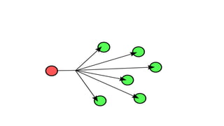
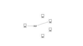
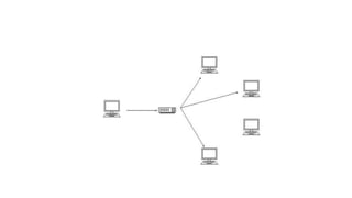
• In computer networking, telecommunication and information
theory, broadcasting is a method of transferring a message to
all recipients simultaneously. Broadcasting can be performed as
a high-level operation in a program, for example, broadcasting
in Message Passing Interface, or it may be a low-level
networking operation, for example broadcasting on Ethernet.
• All-to-all communication is a computer
communication method in which each sender transmits
messages to all receivers within a group.[1] In networking this
can be accomplished using broadcast or multicast. This is in
contrast with the point-to-point method in which each sender
communicates with one receiver.