Download as PDF, PPTX


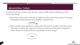
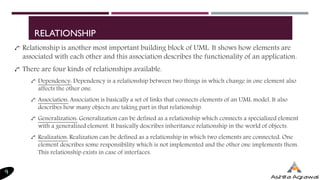
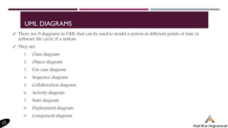
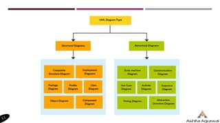

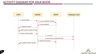
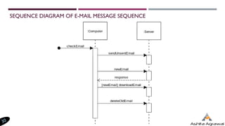
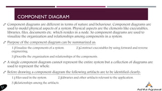
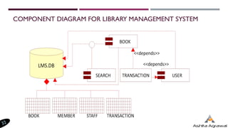
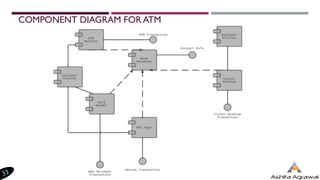

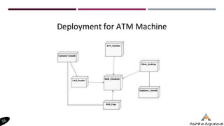

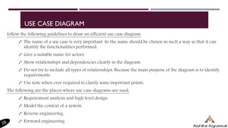


The document provides an introduction to Unified Modeling Language (UML), detailing its significance in specifying, visualizing, constructing, and documenting software systems. It discusses the building blocks of UML, including structural and behavioral things, relationships, and various types of UML diagrams used to model systems throughout their lifecycle. Furthermore, it outlines the purposes and guidelines for creating different UML diagrams such as class diagrams, state diagrams, activity diagrams, sequence diagrams, component diagrams, and use case diagrams.