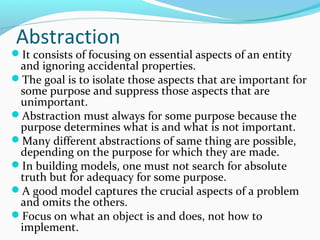
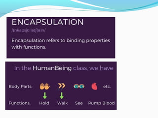
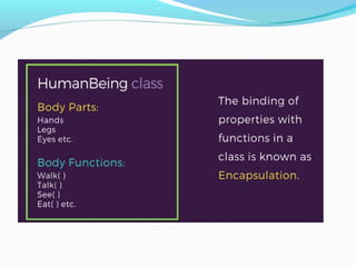
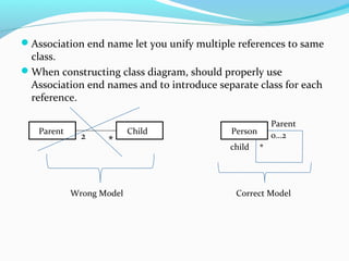
This document discusses object-oriented concepts and modeling. It begins by listing three textbooks on these topics. It then provides an overview of object-oriented concepts like objects, classes, inheritance, polymorphism, and encapsulation. It describes the stages of object-oriented analysis, design and implementation. It discusses the three main models used in object-oriented modeling: class models, state models, and interaction models. Finally, it covers object-oriented themes like abstraction, encapsulation, and polymorphism and the purposes of modeling.
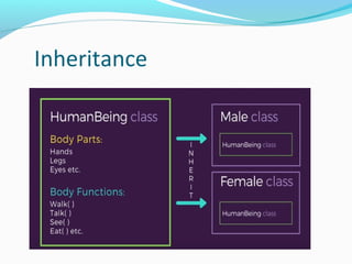
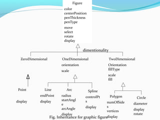
![Inheritance
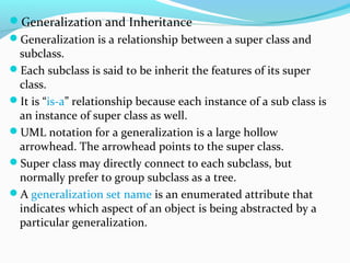
It is the sharing of attributes and operations among
classes based on a hierarchical relationship.
Super class has general information.
Subclasses can be formed from broadly defined
class[Super class].
Each subclass incorporates or inherits all the
properties of its super class and adds its own unique
properties.](https://image.slidesharecdn.com/oomdunit1-190427094255/85/Oomd-unit1-17-320.jpg)


![[Deck] What's New in Spark-Iceberg Integration via DSV2.pptx](https://cdn.slidesharecdn.com/ss_thumbnails/deckwhatsnewinspark-icebergintegrationviadsv2-260210005337-25955b12-thumbnail.jpg?width=640&height=640&fit=bounds)


