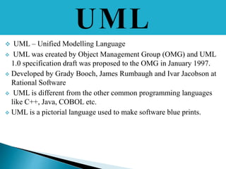
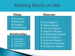
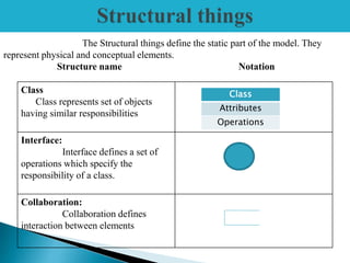
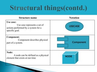
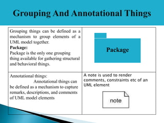
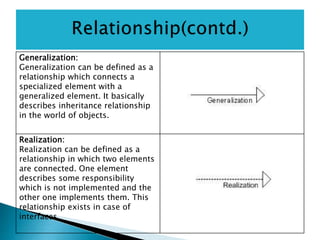
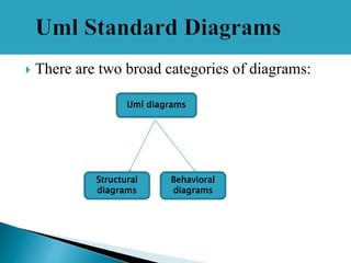
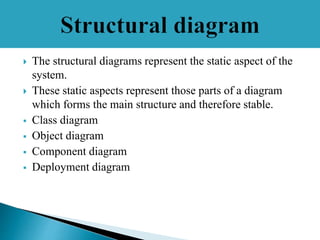
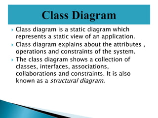
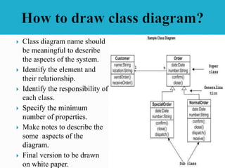
DONE BY
D.STELLA(140071601073)
D.STEFFY(140071601072)
A.SHREEN FATHIMA(140071601068)
 UML – Unified Modelling Language
 UML was created by Object Management Group (OMG) and UML
1.0 specification draft was proposed to the OMG in January 1997.
 Developed by Grady Booch, James Rumbaugh and Ivar Jacobson at
Rational Software
 UML is different from the other common programming languages
like C++, Java, COBOL etc.
 UML is a pictorial language used to make software blue prints.
 UML is a standard language for specifying, visualizing,
constructing, and documenting the artifacts of software
systems.
 A conceptual model can be defined as a model which is
made of concepts and their relationships.
 UML building blocks
 Rules to connect the building blocks
 Common mechanisms of UML
Things Diagrams
Relationships
Structural
Behavioral
Grouping
Annotational
 Dependency
 Association
 Generalisation
 Realization
 Class diagram
 Object diagram
 Use case diagram
 Sequence diagram
 Collaboration diagram
 Activity diagram
 Statechart diagram
 Deployment diagram
 Component diagram
Class
Class represents set of objects
having similar responsibilities
Interface:
Interface defines a set of
operations which specify the
responsibility of a class.
Collaboration:
Collaboration defines
interaction between elements
The Structural things define the static part of the model. They
represent physical and conceptual elements.
Structure name Notation
Class
Attributes
Operations
Structure name Notation
Use case:
Use case represents a set of
actions performed by a system for a
specific goal.
Component:
Component describes physical
part of a system.
Node:
A node can be defined as a physical
element that exists at run time
USECASE
Component
NODE
 A behavioral thing consists of the dynamic parts of UML models.
Structure name Notation
Interaction:
Interaction is defined as a
behavior that consists of a group of
messages exchanged among elements
to accomplish a specific task. Eg:
Message
State machine:
A behavior that specifies the
sequences of states an object goes
through during its' lifetime in response
to events.
State
Diagram
Grouping things can be defined as a
mechanism to group elements of a
UML model together.
Package:
Package is the only one grouping
thing available for gathering structural
and behavioral things.
Annotational things:
Annotational things can
be defined as a mechanism to capture
remarks, descriptions, and comments
of UML model elements
A note is used to render
comments, constraints etc of an
UML element
.
Package
 Relationship is another most important building block of UML. It shows how
elements are associated with each other and this association describes the
functionality of an application.
Dependency is a relationship
between two things in which
change in one element also affects
the other one.
Association is basically a set of links
that connects elements of an UML
model. It also describes how many
objects are taking part in that
relationship.
Generalization:
Generalization can be defined as a
relationship which connects a
specialized element with a
generalized element. It basically
describes inheritance relationship
in the world of objects.
Realization:
Realization can be defined as a
relationship in which two elements
are connected. One element
describes some responsibility
which is not implemented and the
other one implements them. This
relationship exists in case of
interfaces.
 There are two broad categories of diagrams:
Uml diagrams
Structural
diagrams
Behavioral
diagrams
 The structural diagrams represent the static aspect of the
system.
 These static aspects represent those parts of a diagram
which forms the main structure and therefore stable.
 Class diagram
 Object diagram
 Component diagram
 Deployment diagram
 Class diagram is a static diagram which
represents a static view of an application.
 Class diagram explains about the attributes ,
operations and constraints of the system.
 The class diagram shows a collection of
classes, interfaces, associations,
collaborations and constraints. It is also
known as a structural diagram.
 Class diagram name should
be meaningful to describe
the aspects of the system.
 Identify the element and
their relationship.
 Identify the responsibility of
each class.
 Specify the minimum
number of properties.
 Make notes to describe the
some aspects of the
diagram.
 Final version to be drawn
on white paper.
 Component diagrams are used to model physical aspects of a
system.
 Physical aspects are the elements like executables, libraries,
files, documents etc which resides in a node.
 Component diagrams represent a set of components and their
relationships. These components consist of classes, interfaces
or collaborations.
 Component diagrams are used to visualize the organization
and relationships among components in a system. These
diagrams are also used to make executable systems
To draw a component diagram the
following artifacts are to be identified
clearly:
 Files used in the system.
 Libraries and other artifacts
relevant to the application.
 Relationships among the
artifacts.
 Use a meaningful name to
identify the component for which the
diagram is to be drawn.
 Prepare a mental layout before
producing using tools.
 Use notes for clarifying
important points.
 Object diagrams are derived from class diagrams
 Object diagrams can be described as an instance of
class diagram.
 Object diagrams are a set of objects and their
relationships just like class diagrams and also
represent the static view of the system.
 Object diagram represents an instance at a particular
moment
 This diagram is an instance of
the system at a time of
purchase.
 Objects identified are customer,
order, Special order and normal
order.
 The customer object (C) is
associated with three order
objects (O1, O2 and O3). These
order objects are associated
with special order and normal
order objects (S1, S2 and N1).
The customer is having the
following three orders with
different numbers (12, 32 and
40) for the particular time.
 Deployment diagrams are a set of nodes and their
relationships. These nodes are physical entities where the
components are deployed.
 Deployment diagrams are used for visualizing deployment
view of a system. This is generally used by the deployment
team.
 A deployment diagram consists of nodes. Nodes are nothing
but physical hardwares used to deploy the application.
Before drawing a deployment diagram
the following artifacts should be
identified:
Nodes
Relationships among nodes
Here we have shown nodes as:
Monitor
Modem
Caching server
Server
The application is assumed to be a web
based application which is deployed in
a clustered environment using server
1, server 2 and server 3. The user is
connecting to the application using
internet. The control is flowing from
the caching server to the clustered
environment.
 Represents the dynamic aspects
 Help visualize , specify and construct and
document the dynamic aspects of a software.
 Dynamic aspects like use case, interaction,
state chart, activity.
• Use Case Diagram – high-level behaviors of the system,
user goals, external entities: actors
• Sequence Diagram – focus on time ordering of messages
• Collaboration Diagram – focus on structural
organization of objects and messages
• State Chart Diagram – event driven state changes of
system
• Activity Diagram – flow of control between activities
 Use case diagrams present an outside view of the
manner the elements in a system behave and how they
can be used in the context.
 Use case diagrams comprise of: Use cases, Actors,
Relationships like dependency, generalization, and
association.
 Uses: To model the context of a system by enclosing
all the activities of a system within a rectangle and
focusing on the actors outside the system by
interacting with it.
 i.e. To model the requirements of a system from the
outside point of view.
USE CASE
• Use case captures some
user-visible functionality
• Granularity of functionality
depends on the level of
detail in your model
• Each use case achieves a
discrete goal for the user
• Use Cases are generated
through requirements
elicitation
ACTOR
• Actors have a name.
• An actor is a set of roles
that users of use cases play
when interacting with the
system.
• They are external entities
• They may be external an
system or DB
Use case
 Let us consider an Automated Trading System.
 We assume the following features of the system:
The trading has transactions with two types of
customers, individual customers and corporate
customers.
 Once the customer places an order, it is processed
by the sales department and the customer is given
the bill.
 The system allows the manager to manage
customer accounts and answer any queries posted
by the customer.
Actor
Usecase
diagram
 Main purpose of the interaction diagram is to
visualize the interactive behavior of the system.
 Messages exchanged between these objects will
be specified in the diagram itself.
 There are two types of interaction diagrams.
1.Sequence diagrams
2.collaboratoion diagrams
 Sequence diagram is an interaction diagram.
 Sequence diagrams are interaction diagrams
that illustrate the ordering of messages
according to time
 Sequence diagrams represent the objects
which are participating in the interaction
horizontally and time vertically.
 Collaboration diagram is another form of
interaction diagram.
 Collaboration diagrams are interaction
diagrams that illustrate the structure of the
objects that send and receive messages.
 Structural organization consists of objects
and links.
 A state–chart diagram shows a state machine that
depicts the control flow of an object from one
state to another.
 A state machine portrays the sequences of states
which an object undergoes due to events and
their responses to events.
 State–Chart Diagrams comprise of:
-States: Simple or Composite
-Transitions between states
-Events causing transitions
-Actions due to the events
 Used for: State-chart diagrams are used for
modeling objects which are reactive in nature.
Consider – ORDER as an Object and trace its
sequence
Transition
between
states
Event causing
Transition
Simple
state
Action due
to event
 An activity diagram depicts the flow of
activities which are ongoing operations in a
state machine.
 Activity diagram describes the flow of control
in a system. So it consists of activities and
links.
 Activity diagram is basically a flow chart to
represent the flow form one activity to
another activity. The activity can be described
as an operation of the system.
 Following elements to
be identified before
drawing an activity
diagram.
 Activities
 Association
 Conditions
 Constraints
Three type of UMLmodelling:
Structural,Behavioural and Architectural
Structural Modelling
 Structural Modelling capture the static
features of the system.
 Structural model represents the
framework for the system.
 This framework is the place where all
other components exist.
 They all represent the elements and the
mechanism to assemble them.
 It never describes about the dynamic
behaviour of the system.
 Class diagram is the most widely used
diagram.
1. Classes diagrams
2. Objects diagrams
3. Package diagrams
4. Deployment
diagrams
5. Composite structure
diagram
6. Component diagram
 Behavioral model describes the interaction in the system.
 It represents the interaction among the structural
diagrams.
 It shows the dynamic nature of the system.
They consists of the following:
1.Activity diagrams
2.Interaction diagrams
3.Use case diagrams
 All the above show the dynamic sequence of flow in a
system.
 Architectural model represents the overall
framework of the system.
 It contains both structural and behavioral
elements of the system.
 It can be defined as the blueprint of the entire
system.
 Package diagram comes under architectural
modelling.
Uml

Uml

  • 1.
  • 2.
     UML –Unified Modelling Language  UML was created by Object Management Group (OMG) and UML 1.0 specification draft was proposed to the OMG in January 1997.  Developed by Grady Booch, James Rumbaugh and Ivar Jacobson at Rational Software  UML is different from the other common programming languages like C++, Java, COBOL etc.  UML is a pictorial language used to make software blue prints.
  • 3.
     UML isa standard language for specifying, visualizing, constructing, and documenting the artifacts of software systems.  A conceptual model can be defined as a model which is made of concepts and their relationships.  UML building blocks  Rules to connect the building blocks  Common mechanisms of UML
  • 4.
    Things Diagrams Relationships Structural Behavioral Grouping Annotational  Dependency Association  Generalisation  Realization  Class diagram  Object diagram  Use case diagram  Sequence diagram  Collaboration diagram  Activity diagram  Statechart diagram  Deployment diagram  Component diagram
  • 5.
    Class Class represents setof objects having similar responsibilities Interface: Interface defines a set of operations which specify the responsibility of a class. Collaboration: Collaboration defines interaction between elements The Structural things define the static part of the model. They represent physical and conceptual elements. Structure name Notation Class Attributes Operations
  • 6.
    Structure name Notation Usecase: Use case represents a set of actions performed by a system for a specific goal. Component: Component describes physical part of a system. Node: A node can be defined as a physical element that exists at run time USECASE Component NODE
  • 7.
     A behavioralthing consists of the dynamic parts of UML models. Structure name Notation Interaction: Interaction is defined as a behavior that consists of a group of messages exchanged among elements to accomplish a specific task. Eg: Message State machine: A behavior that specifies the sequences of states an object goes through during its' lifetime in response to events. State Diagram
  • 8.
    Grouping things canbe defined as a mechanism to group elements of a UML model together. Package: Package is the only one grouping thing available for gathering structural and behavioral things. Annotational things: Annotational things can be defined as a mechanism to capture remarks, descriptions, and comments of UML model elements A note is used to render comments, constraints etc of an UML element . Package
  • 9.
     Relationship isanother most important building block of UML. It shows how elements are associated with each other and this association describes the functionality of an application. Dependency is a relationship between two things in which change in one element also affects the other one. Association is basically a set of links that connects elements of an UML model. It also describes how many objects are taking part in that relationship.
  • 10.
    Generalization: Generalization can bedefined as a relationship which connects a specialized element with a generalized element. It basically describes inheritance relationship in the world of objects. Realization: Realization can be defined as a relationship in which two elements are connected. One element describes some responsibility which is not implemented and the other one implements them. This relationship exists in case of interfaces.
  • 11.
     There aretwo broad categories of diagrams: Uml diagrams Structural diagrams Behavioral diagrams
  • 12.
     The structuraldiagrams represent the static aspect of the system.  These static aspects represent those parts of a diagram which forms the main structure and therefore stable.  Class diagram  Object diagram  Component diagram  Deployment diagram
  • 13.
     Class diagramis a static diagram which represents a static view of an application.  Class diagram explains about the attributes , operations and constraints of the system.  The class diagram shows a collection of classes, interfaces, associations, collaborations and constraints. It is also known as a structural diagram.
  • 14.
     Class diagramname should be meaningful to describe the aspects of the system.  Identify the element and their relationship.  Identify the responsibility of each class.  Specify the minimum number of properties.  Make notes to describe the some aspects of the diagram.  Final version to be drawn on white paper.
  • 15.
     Component diagramsare used to model physical aspects of a system.  Physical aspects are the elements like executables, libraries, files, documents etc which resides in a node.  Component diagrams represent a set of components and their relationships. These components consist of classes, interfaces or collaborations.  Component diagrams are used to visualize the organization and relationships among components in a system. These diagrams are also used to make executable systems
  • 16.
    To draw acomponent diagram the following artifacts are to be identified clearly:  Files used in the system.  Libraries and other artifacts relevant to the application.  Relationships among the artifacts.  Use a meaningful name to identify the component for which the diagram is to be drawn.  Prepare a mental layout before producing using tools.  Use notes for clarifying important points.
  • 17.
     Object diagramsare derived from class diagrams  Object diagrams can be described as an instance of class diagram.  Object diagrams are a set of objects and their relationships just like class diagrams and also represent the static view of the system.  Object diagram represents an instance at a particular moment
  • 18.
     This diagramis an instance of the system at a time of purchase.  Objects identified are customer, order, Special order and normal order.  The customer object (C) is associated with three order objects (O1, O2 and O3). These order objects are associated with special order and normal order objects (S1, S2 and N1). The customer is having the following three orders with different numbers (12, 32 and 40) for the particular time.
  • 19.
     Deployment diagramsare a set of nodes and their relationships. These nodes are physical entities where the components are deployed.  Deployment diagrams are used for visualizing deployment view of a system. This is generally used by the deployment team.  A deployment diagram consists of nodes. Nodes are nothing but physical hardwares used to deploy the application.
  • 20.
    Before drawing adeployment diagram the following artifacts should be identified: Nodes Relationships among nodes Here we have shown nodes as: Monitor Modem Caching server Server The application is assumed to be a web based application which is deployed in a clustered environment using server 1, server 2 and server 3. The user is connecting to the application using internet. The control is flowing from the caching server to the clustered environment.
  • 21.
     Represents thedynamic aspects  Help visualize , specify and construct and document the dynamic aspects of a software.  Dynamic aspects like use case, interaction, state chart, activity.
  • 22.
    • Use CaseDiagram – high-level behaviors of the system, user goals, external entities: actors • Sequence Diagram – focus on time ordering of messages • Collaboration Diagram – focus on structural organization of objects and messages • State Chart Diagram – event driven state changes of system • Activity Diagram – flow of control between activities
  • 23.
     Use casediagrams present an outside view of the manner the elements in a system behave and how they can be used in the context.  Use case diagrams comprise of: Use cases, Actors, Relationships like dependency, generalization, and association.  Uses: To model the context of a system by enclosing all the activities of a system within a rectangle and focusing on the actors outside the system by interacting with it.  i.e. To model the requirements of a system from the outside point of view.
  • 24.
    USE CASE • Usecase captures some user-visible functionality • Granularity of functionality depends on the level of detail in your model • Each use case achieves a discrete goal for the user • Use Cases are generated through requirements elicitation ACTOR • Actors have a name. • An actor is a set of roles that users of use cases play when interacting with the system. • They are external entities • They may be external an system or DB Use case
  • 25.
     Let usconsider an Automated Trading System.  We assume the following features of the system: The trading has transactions with two types of customers, individual customers and corporate customers.  Once the customer places an order, it is processed by the sales department and the customer is given the bill.  The system allows the manager to manage customer accounts and answer any queries posted by the customer.
  • 26.
  • 27.
     Main purposeof the interaction diagram is to visualize the interactive behavior of the system.  Messages exchanged between these objects will be specified in the diagram itself.  There are two types of interaction diagrams. 1.Sequence diagrams 2.collaboratoion diagrams
  • 28.
     Sequence diagramis an interaction diagram.  Sequence diagrams are interaction diagrams that illustrate the ordering of messages according to time  Sequence diagrams represent the objects which are participating in the interaction horizontally and time vertically.
  • 30.
     Collaboration diagramis another form of interaction diagram.  Collaboration diagrams are interaction diagrams that illustrate the structure of the objects that send and receive messages.  Structural organization consists of objects and links.
  • 32.
     A state–chartdiagram shows a state machine that depicts the control flow of an object from one state to another.  A state machine portrays the sequences of states which an object undergoes due to events and their responses to events.  State–Chart Diagrams comprise of: -States: Simple or Composite -Transitions between states -Events causing transitions -Actions due to the events  Used for: State-chart diagrams are used for modeling objects which are reactive in nature.
  • 33.
    Consider – ORDERas an Object and trace its sequence Transition between states Event causing Transition Simple state Action due to event
  • 34.
     An activitydiagram depicts the flow of activities which are ongoing operations in a state machine.  Activity diagram describes the flow of control in a system. So it consists of activities and links.  Activity diagram is basically a flow chart to represent the flow form one activity to another activity. The activity can be described as an operation of the system.
  • 35.
     Following elementsto be identified before drawing an activity diagram.  Activities  Association  Conditions  Constraints
  • 36.
    Three type ofUMLmodelling: Structural,Behavioural and Architectural Structural Modelling  Structural Modelling capture the static features of the system.  Structural model represents the framework for the system.  This framework is the place where all other components exist.  They all represent the elements and the mechanism to assemble them.  It never describes about the dynamic behaviour of the system.  Class diagram is the most widely used diagram. 1. Classes diagrams 2. Objects diagrams 3. Package diagrams 4. Deployment diagrams 5. Composite structure diagram 6. Component diagram
  • 37.
     Behavioral modeldescribes the interaction in the system.  It represents the interaction among the structural diagrams.  It shows the dynamic nature of the system. They consists of the following: 1.Activity diagrams 2.Interaction diagrams 3.Use case diagrams  All the above show the dynamic sequence of flow in a system.
  • 38.
     Architectural modelrepresents the overall framework of the system.  It contains both structural and behavioral elements of the system.  It can be defined as the blueprint of the entire system.  Package diagram comes under architectural modelling.