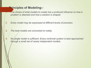
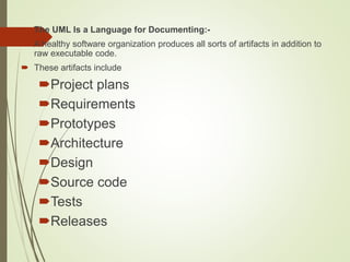
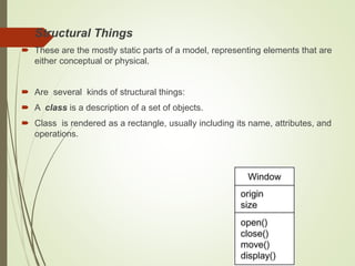
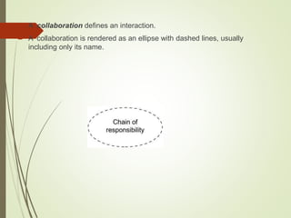
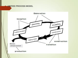
The document provides an introduction to the Unified Modeling Language (UML). It discusses the key principles of modeling and an overview of UML. The UML is a standard language for writing software blueprints and can be used to visualize, specify, construct, and document software systems. The UML has building blocks like classes, objects, use cases and relationships. It consists of diagrams like class diagrams, sequence diagrams, and state machine diagrams. The UML addresses multiple views of a system including use case, design, interaction and implementation views.
2. ī´ Principles of Modeling:-
1. The choice of what models to create has a profound influence on how a
problem is attacked and how a solution is shaped.
2. Every model may be expressed at different levels of precision.
3. The best models are connected to reality.
4. No single model is sufficient. Every nontrivial system is best approached
through a small set of nearly independent models.
3. Overview of the UML
ī´ The Unified Modeling Language (UML) is a standard
language for writing software blueprints.
ī´ The UML may be used to visualize, specify, construct, and
document the artifacts of a software intensive system.
4. ī´ The UML Is a Language:-
ī´ A modeling language is a language whose vocabulary and rules focus on
the conceptual and physical representation of a system.
ī´ The UML Is a Language for Visualizing:
ī´ For many programmers, the distance between thinking of an
implementation and then pounding it out in code is close to zero.
ī´ The UML Is a Language for Specifying:
ī´ UML addresses the specification of all the important analysis, design, and
implementation decisions that must be made in developing and deploying a
software-intensive system.
5. ī´ The UML Is a Language for Constructing:-
ī´ The UML is not a visual programming language, but its models can be
directly connected to a variety of programming languages.
ī´ This means that it is possible to map from a model in the UML to a
programming language such as Java, C++, or Visual Basic.
6. ī´ The UML Is a Language for Documenting:-
ī´ A healthy software organization produces all sorts of artifacts in addition to
raw executable code.
ī´ These artifacts include
ī´Project plans
ī´Requirements
ī´Prototypes
ī´Architecture
ī´Design
ī´Source code
ī´Tests
ī´Releases
7. ī´ Where Can the UML Be Used?
ī´ The UML is intended primarily for software-intensive systems. It has been
used effectively for such domains as
ī´ Enterprise information systems
ī´ Banking and financial services
ī´ Telecommunications
ī´ Transportation
ī´ Defense/aerospace
ī´ Retail
ī´ Medical
ī´ Electronics
ī´ Scientific
ī´ Distributed Web-based services
8.
9. Object-Oriented Modeling
ī´ In software, there are several ways to approach a model.
The two most common ways are from an algorithmic
perspective and from an object-oriented perspective.
ī´ From an algorithmic perspective, the main building block of
all software is the procedure or function.
ī´ From an object-oriented perspective, the main building
block of all software systems is the object or class.
ī´ Every object has identity, state and behavior.
10. A Conceptual Model of the
UML
ī´ Conceptual model requires learning three major elements:
1. The UML's basic building blocks.
2. The rules of the UML.
3. Common mechanisms of the UML.
11. ī´ Building Blocks of the UML:-
ī´ The vocabulary of the UML encompasses three kinds of building blocks:
1. Things
2. Relationships
3. Diagrams
12. 1. Things in the UML
ī´ Things are the abstractions that are first-class citizens in a model.
ī´ There are four kinds of things in the UML:
1. Structural things.
2. Behavioral things.
3. Grouping things.
4. Annotational things.
13. ī´ Structural Things
ī´ These are the mostly static parts of a model, representing elements that are
either conceptual or physical.
ī´ Are several kinds of structural things:
ī´ A class is a description of a set of objects.
ī´ Class is rendered as a rectangle, usually including its name, attributes, and
operations.
14. ī´ An interface is a collection of operations that specify a service of a class or
component.
ī´ An interface rarely stand alone.
ī´ An interface provided by a class to the outside world is shown as a small
circle attached to the class box by a line.
ī´ An interface required by a class from some other class is shown as a small
semicircle attached to the class box by a line.
15. ī´ A collaboration defines an interaction.
ī´ A collaboration is rendered as an ellipse with dashed lines, usually
including only its name.
16. ī´ A use case is a description of set of sequence of actions that a system
performs that yields an observable result of value to a particular actor.
ī´ A use case is rendered as an ellipse with solid lines, usually including only
its name
17. ī´ An active class is a class whose objects own one or more processes or
threads and therefore can initiate control activity.
ī´ An active class is rendered just like a class, but with heavy lines, usually
including its name, attributes, and operations.
18. ī´ A component is a modular part of the system design that hides its
implementation behind a set of external interfaces.
ī´ A component is rendered like a class with a special icon in the upper right
corner.
19. ī´ Node is used to represent physical part of a system like server, network
etc..
ī´ A node is rendered as a cube, usually including only its name.
20. ī´ Behavioral Things:-
ī´ Behavioral things are the dynamic parts of UML models.
ī´ An interaction is a behavior that comprises a set of messages exchanged
among a set of objects.
ī´ A message is rendered as a directed line, almost always including the
name of its operation.
21. ī´ A state machine is a behavior that specifies the sequences of states an
object.
ī´ A state is rendered as a rounded rectangle, usually including its name and
its substates.
22. ī´ An activity is a behavior that specifies the sequence of steps a
computational process performs.
ī´ A step of an activity is called an action.
ī´ An action is rendered as a rounded rectangle with a name indicating its
purpose.
ī´ States & actions are distinguished by their different contexts.
process order
23. ī´ Grouping Things
ī´ Grouping things are the organizational parts of UML models.
ī´ A package is a general-purpose mechanism for organizing elements into
groups.
ī´ Structural things, behavioral things, and even other grouping things may be
placed in a package.
ī´ Packages is purely conceptual.
ī´ A package is rendered as a tabbed folder, usually including only its name
and, sometimes, its contents
24. ī´ Annotational Things
ī´ Annotational things are the explanatory parts of UML models.
ī´ A note is simply a symbol for rendering constraints and comments attached
to an element or a collection of elements.
ī´ A note is rendered as a rectangle with a dog-eared corner, together with a
textual or graphical comment.
25. 2. Relationships in the UML
ī´ There are four kinds of relationships in the UML:
1. Dependency
2. Association
3. Generalization
4. Realization
26. ī´ A dependency is a semantic relationship between two things in which a
change to one thing may affect the semantics of the other thing.
ī´ A dependency is rendered as a dashed line, possibly directed, and
occasionally including a label.
27. ī´ An association is a structural relationship that describes a set of links, a
link being a connection among objects.
ī´ An association is rendered as a solid line, possibly directed, occasionally
including a label.
28. ī´ A generalization is a specialization/generalization relationship in which
objects of the specialized element (the child) are substitutable for objects of
the generalized element.
ī´ A generalization relationship is rendered as a solid line with a hollow
arrowhead pointing to the parent.
29. ī´ A realization relationship is a relationship between two model elements, in
which one model element (the client) realizes the behavior that the other
model element (the supplier) specifies.
ī´ Realization relationship is rendered as a cross between a generalization
and a dependency relationship.
30. ī´ Diagrams in the UML:-
ī´ A diagram is the graphical presentation of a set of elements, most often
presented as a connected graph of things and relationships.
ī´ UML includes few kinds of diagrams.
1. Class diagram consists of classes, interfaces, associations and
collaboration.
ī´ Class diagrams basically represent the object oriented view of a system which
is static in nature.
31. 2. Object diagrams are a set of objects and their relationships.
ī´ Object diagram represent the static view of the system.
3. Component diagrams represent a set of components and their
relationships. These components consist of classes, interfaces or
collaborations.
ī´ Component diagrams represent the implementation view of a system.
32. 4. A use case diagram represents a particular functionality of a system.
ī´ Represent the use case view of a system.
5. A sequence diagram is an interaction diagram.
ī´ Interaction among the components of a system is very important from
implementation and execution perspective.
ī´ Represent the dynamic view of interaction.
33. 6. Communication diagram is an interaction diagram that highlight the
structural organization of the objects that send and receive messages.
7. A state diagram shows a state machine, consisting of states, transitions,
events, and activities.
ī´ State diagrams address the dynamic view of a system.
8. Activity diagram describes the flow of control in a system.
ī´ Activity diagrams address the dynamic view of a system
34. 9. Deployment diagrams are a set of nodes and their relationships.
ī´ These nodes are physical entities where the components are deployed.
10. Artifact diagram shows the physical element of a system on the computer.
ī´ Artifacts include files, database etc.
35. 11. Package diagram shows the decomposition of the model itself into
organization units & their dependencies.
12. Timing diagram is an interaction diagram that shows actual times across
different objects, relative sequences of messages.
13. Interaction overview diagram is hybrid of activity & sequence diagram.
36. ī´ Rules of the UML:-
ī´ A well-formed model is one that is semantically
self-consistent and in synchronization with all its related models.
ī´ The UML has semantic rules for
ī´ Names:- What you can call things, relationships, and diagrams.
ī´ Scope:- The context that gives specific meaning to a name
ī´ Visibility:- How those names can be seen and used by others
ī´ Integrity:- How things properly and consistently relate to one another
ī´ Execution:- What it means to run or simulate a dynamic model
37. ī´ It is common for the development team to not only build models that are
well-formed, but also to build models that are:
ī´ Elided:- Certain elements are hidden to simplify the view
ī´ Incomplete:- Certain elements may be missing
ī´ Inconsistent:- The integrity of the model is not guaranteed
38. ī´ Common Mechanisms in the UML:-
ī´ UML is made simpler by the presence of four common mechanisms that
apply consistently throughout the language.
1. Specifications
2. Adornments
3. Common divisions
4. Extensibility mechanisms
39. ī´ Specifications
ī´ Specifying something in a bit more detail so that the role and meaning of
the term being specified is presented to us in a more clear.
ī´ Adornments
ī´ Adornments are textual or graphical items, which can be added to the basic
notation of a UML building block in order to visualize some details from that
elementâs specification.
ī´ One of the most important kinds of adornments is a note
40. ī´ Common Divisions
ī´ In modeling Object Oriented systems, the world often gets divided in several
ways.
ī´ First, there is the division of class and object.
A class is an abstraction; an object is one concrete manifestation of that
abstraction.
ī´ Graphically, the UML distinguish an object by using the same symbol as its
class and then simply underlying the objects name.
41. ī´ Second, there is the separation of interface and implementation.
ī´ An interface declares a contract.
ī´ An implementation represents one concrete realization of that contract,
responsible for faithfully carrying out the interface's complete semantics.
42. ī´ Extensibility Mechanisms: â UML is opened ended language, making it
possible for You to extend the language in controlled ways:
ī´
There are three:-
Stereotype:- Stereotypes allow you to extend the vocabulary of the UML
so that you can create new model elements, derived from existing ones, but
that have specific properties that are suitable for your problem domain.
ī´
Tagged value:- A tagged value extends the properties of UML building
blocks ,allowing user to create new information in that elementary
specification.
ī´
Constraint: â This allows user to add new rules or modify existing ones.
43. ī´ Architecture of modeling systemâs
ī´ A system's architecture is perhaps the most important artifact that can be
used to manage these different viewpoints and so control the iterative and
incremental development of a system throughout its life cycle.
44. ī´ Architecture is the set of significant decisions about
ī´ The organization of a software system.
ī´ The selection of the structural elements and their interfaces by which the
system is composed.
ī´ Their behavior, as specified in the collaborations among those elements.
ī´ The composition of these structural and behavioral elements into progressively
larger subsystems.
ī´ The architectural style that guides this organization
45. ī´ The use case view of a system encompasses the use cases that describe
the behavior of the system as seen by its end users, analysts, and testers.
ī´ The design view of a system encompasses the classes, interfaces, and
collaborations that form the vocabulary of the problem and its solution.
ī´ The interaction view of a system shows the flow of control among its
various parts, including possible concurrency & synchronization
mechanisms.
46. ī´ The implementation view of a system encompasses the components and
files that are used to assemble and release the physical system.
ī´ The deployment view of a system encompasses the nodes that form the
system's hardware topology on which the system executes
48. ī´ The nature of an object:-
ī´ We define an object as a tangible entity that exhibits some well-defined
behavior.
ī´ An object has state, exhibits come well-defined behavior, & has a unique
identity.
ī´ An object is any of the following:-
ī´A tangible &/or visible thing.
ī´Something that may be apprehended intellectually.
ī´Something towards which thought or action is
directed.
49. ī´ Real-world objects share two characteristics: They all have state and
behavior.
ī´ State : Every object, at any given point of time would have to have a set of
attributes defining its State.
ī´ Behavior : Every object based on its state and optionally identity will have
particular behavior.
ī´ Eg:-Dogs have state (name, color, breed, hungry) and behavior (barking,
fetching, wagging tail).
ī´ Bicycles also have state (current gear, current pedal cadence, current
speed) and behavior (changing gear, changing pedal cadence, applying
brakes)
50. ī´ THE PROPERTY (OBJECT ATTRIBUTE)
ī´ Properties are variables contained in the class; every instance of the object
has those properties.
ī´ The methods:-
ī´ Methods follow the same logic as properties.
ī´ The difference is that they are functions and they are defined as functions.
ī´ Calling a method is similar to accessing a property, but you add () at the
end of the method name, possibly with arguments.
51. ī´ The messages :-
ī´ An object-oriented program is a growing and shrinking collection of objects
that interact via messages.
ī´ Objects can send and receive messages.
ī´ Over its lifetime, the object has a state that varies.
ī´ A message is called a request or an event.
ī´ The event contains the name of the object, the name of the operation, and
maybe a group of parameters.
52. ī´ Object â Oriented Systems Development Life Cycle:-
ī´ The essence of the software Development Process that consists of
ī´ Analysis ,
ī´ Design ,
ī´ Implementation ,
ī´ Testing , and
ī´ Refinement
ī´ To transform usersâ needs into a software solution that satisfy the needs.
53. ī´ The object oriented approach requires a more rigorous process to do things
right more rigorous process to do things right.
ī´ You need not see code until after about 25 percent of the development time,
because you need to spend more time in gathering requirements,
developing a requirement model and an analysis model, then turning them
into the design model.
54.
55. ī´ The software development process also can be divided into smaller,
interacting subprocesses.
ī´ Generally, the software development process can be viewed as a series of
transformations, where the output of one transformation becomes the input
of the subsequent transformation.
56. ī´ Transformation1(Analysis):
ī´ Translates the userâs needs into system requirements and responsibilities.
ī´ The way they use the system can provide insight into the userâs
requirements.
ī´ For example: one use of system might be analyzing an incentive payroll
system, which will tell us that this capacity will be included in the system
requirements.
57. ī´ Transformation 2 (design):
ī´ Begins with a problem statement and ends with a detailed design that can
be transformed into a operational system.
ī´ This transformation includes the bulk of the software development activity,
including the definition of how to build the software, its development, and its
testing.
ī´ It also includes design descriptions, the programs and the testing material.
58. ī´ Transformation 3(Implementation)
ī´ Refines the detailed design into the system deployment that will satisfy the
userâs needs.
ī´ This takes into account equipment, procedures, people, and the like.
ī´ It represents embedding the software product within its operational
environment.
59. ī´ ADVANTAGES OF OBJECT ORIENTED METHODOLOGY
ī´ Object Oriented Methodology closely represents the problem domain.
Because of this, it is easier to produce and understand designs.
ī´ The objects in the system are safe to requirement changes. Therefore,
allows changes more easily.
ī´ Object Oriented Methodology designs encourage more re-use. New
applications can use the existing modules, thereby reduces the
development cost and cycle time.
60. ī´ Object Oriented Methodology approach is more natural. It provides nice
structures for thinking and abstracting and leads to modular design.
61. ī´ The object-modeling technique (OMT) is an object modeling language for
software modeling and designing.
ī´ It was developed by Rumbaugh, Blaha, Premerlani, Eddy and Lorensen as
a method to develop object-oriented systems, and to support object-
oriented programming.
62. ī´ THE RAMBAUGH OMT
ī´ The purposes of modeling according to Raumbaugh (1991) are:
ī´ Testing physical entities before building them (simulation)
ī´ Communication with customers
ī´ Visualization (alternative presentation of information)
ī´ Reduction of complexity.
63. ī´ The Rambaugh OMT has proposed three main types of models:
ī´ Object model : Main concepts are classes and associations, with attributes
and operations. Aggregation and generalization are predefined
relationships.
ī´ Dynamic model : The dynamic model represents a state/transition view on
the model. Main concepts are states, transitions between states, and events
to trigger transitions. Actions can be modeled as occurring within states.
ī´ Functional model : The functional model handles the process of the model,
corresponding roughly to data flow diagrams. Main concepts are process,
data store, data flow, and actors.
ī´ OMT is a predecessor of the Unified Modeling Language (UML).
64. ī´ THE BOOCH OMT
ī´ The analysis phase is split into steps.
ī´ Customer's Requirements Step:
ī´ The first step is to gather the requirements from the customer
perspective. This analysis step generates a high-level description of the
system's function and structure.
ī´ Domain analysis:
ī´ The domain analysis is done by defining object classes; their attributes,
inheritance, and methods. State diagrams for the objects are then
established.
ī´ The analysis phase is completed with a validation step.
65. ī´ Once the analysis phase is completed, the Booch methodology develops
the architecture in the design phase.
ī´ The design phase is iterative.
ī´ A logic design is mapped to a physical design like processes, performance,
data types, data structures, visibility are defined.
ī´ A prototype is created and tested.
ī´ The process iterates between the logical design, physical design,
prototypes, and testing.
66. ī´ The Booch software engineering methodology is sequential in the sense
that the analysis phase is completed and then the design phase is
completed.
67. ī´ JACOBSON OOSE
ī´ Object-Oriented Software Engineering (OOSE) is a software design
technique that is used in software design in object-oriented programming.
ī´ OOSE is the first object-oriented design methodology that employs use
cases in software design.
ī´ It includes requirements, an analysis, a design, an implementation and a
testing model.
68.
69. ī´ OBJECT-ORIENTED SOFTWARE ENGINEERING LIFE CYCLE
ī´ Requirements Engineering:
ī´ Requirements gathering,
ī´ Object oriented analysis and
ī´ Specification
ī´ OO Design:
ī´ Architectural design
ī´ Detailed design
ī´ Both require the transformation of functional requirements into OO design
elements
70. ī´ Implementation or Coding:
ī´ Programming using OO programming languages and tools.
ī´ Testing:
ī´ Unit testing; test methods within each object
ī´ Integration testing; test collaborations between objects
ī´ System testing; test the entire system as a collection of objects
ī´ Acceptance testing; test for standards and customer satisfaction
72. ī´ Iterative and Incremental:
ī´ The Unified Process is an iterative and incremental development process.
ī´ The Elaboration, Construction and Transition phases are divided into a series of
timeboxed iterations.
ī´ Each iteration results in an increment, which results in improved functionality .
ī´ Use Case Driven:
ī´ In the Unified Process, use cases are used to capture the functional
requirements and to define the contents of the iterations.
73. ī´ Risk Focused
ī´ The Unified Process requires the project team to focus on the most critical risks
early in the project life cycle.
ī´ The deliverables of each iteration, especially in the Elaboration phase, must be
selected in order to ensure that the greatest risks are addressed first.
74. ī´ VIEWS IN UML
1. Functional View:
ī´ This view describes functional requirements of the
system.
ī´ Use case diagrams give static functional view for
functions and static relationships.
ī´ Activity diagrams give dynamic functional view.
2. Static Structural View:
ī´ The class and object diagrams give the structural view of system.
75. 3. Behavioral (dynamic structural) view:
ī´ Interaction diagrams- collaboration diagrams and sequence diagrams
describe sequences of interactions between objects.
ī´ State transition diagrams show state-based behavior of objects.
4. Architectural View:
ī´ This view describes logical and physical structure.
ī´ Component diagrams and deployment diagrams are used in this view
76. Use Case Diagrams
ī´ Use case diagrams are central to modeling the behavior of
a system, a subsystem, or a class.
ī´ Each one shows a set of use cases and actors and their
relationships.
ī´ Use case diagrams are important for visualizing, specifying,
and documenting the behavior of an element.
77. ī´ A use case is a description of a set of sequences of actions, including
variants, that a system performs to yield an observable result of value to an
actor.
ī´ Graphically, a use case is rendered as an ellipse.
ī´ We apply use cases to capture the intended behavior of the system you are
developing, without having to specify how that behavior is implemented.
78. ī´ Use case diagrams commonly contain
ī´ Use cases
ī´ Subject
ī´ Actors
ī´ Dependency, generalization, and association relationships
ī´ Like all other diagrams, use case diagrams may contain notes and
constraints.
79. ī´ Subject:-
ī´ The subject is a class described by a set of use cases.
ī´ The use cases represent aspects of the behavior of the class.
ī´ The actor represent aspects of the other classes that interact with the
subject.
81. ī´ Use Cases and Actors
ī´ An actor represents a role that a human, a hardware device, or even
another system plays with a system.
ī´ Represents an individual interacting with the system in a specific way.
82.
83. ī´ Use Cases and Flow of Events
ī´ A use case describes what a system does but it does not specify how it
does it.
ī´ Flow of event shows the behavior of the use case.
ī´ Flow of events are 2 types:
ī´ Main flow of events
ī´ Exceptional flow of events.
84. ī´ Use Cases and Scenarios
ī´ A scenario is a specific sequence of actions that illustrates behavior.
ī´ Scenario is basically one instance of a use case.
ī´ Use Cases and Collaborations
85. ī´ Organizing Use Cases
ī´ You can organize use cases by grouping them in packages.
ī´ You can also organize use cases by specifying generalization, include, and
extend relationships among them.
ī´ Generalization among use cases is just like generalization among classes.
ī´ An include relationship between use cases means that the base use case
explicitly incorporates the behavior of another use case at a location
specified in the base.
86. ī´ An extend relationship between use cases means that the base use case
implicitly incorporates the behavior of another use case at a location
specified indirectly by the extending use case.
87.
88. ī´ Notation
ī´ The subject is shown as a rectangle containing a set of use case.
ī´ The name of subject is placed within a rectangle.
ī´ The actor are shown as stick figures placed outside the rectangle.
89.
90. ī´ Use-case diagrams are helpful in the following
situations:
ī´ Before starting a project, you can create use-case diagrams to model a
business so that all participants in the project share an understanding
of the workers, customers, and activities of the business.
ī´ While gathering requirements, you can create use-case diagrams to
capture the system requirements and to present to others what the
system should do.
ī´ During the analysis and design phases, you can use the use cases and
actors from your use-case diagrams to identify the classes that the
system requires.
ī´ During the testing phase, you can use use-case diagrams to identify
tests for the system.
92. ī´ Activity is an ongoing structured execution of a behavior.
ī´ Activity is a behavior expressed as a set of actions connected by control &
data flows.
ī´ An activity diagram shows the flow from activity to activity.
ī´ Graphically, an activity diagram is a collection of nodes and arcs.
93. ī´ Activity diagrams commonly contain
ī´ Actions
ī´ Activity nodes
ī´ Flows
ī´ Object values.
ī´ Like all other diagrams, activity diagrams may contain notes and
constraints.
94. ī´ Actions & activity nodes
ī´ You might evaluate some expression that sets the value of an attribute or
that returns some value.
ī´ You might call an operation on an object, send a signal to an object, or
even create or destroy an object.
ī´ These executable, atomic computations are called action.
ī´ Representation of action using a rounded box.
95.
96. ī´ An activity node is an organizational units within an activity.
ī´ Activity nodes are nested grouping of actions.
ī´ An action is an activity node that cannot be further decomposed.
97. ī´ Control Flows
ī´ When the action or activity of a state completes, flow of control passes
immediately to the next action or activity state.
ī´ Indeed, a flow of control has to start and end someplace.
ī´ You may specify this initial state (a solid ball) and stop state (a solid ball
inside a circle).
98.
99. ī´ Branching
ī´ A branch may have one incoming transition and two or more outgoing ones.
ī´ On each outgoing transition, you place a Boolean expression, which is
evaluated only once on entering the branch.
ī´ Guards on the outgoing flow should not overlap but they should cover all
possibilities.
ī´ When two paths of control merge back together, you can also use a
diamond symbol with 2 input arrows & 1 output arrow. No guard are
necessary on merge.
100.
101. ī´ Forking and Joining
ī´ You use a synchronization bar to specify the forking and joining of these
parallel flows of control.
ī´ A synchronization bar is rendered as a thick horizontal or vertical line.
102.
103. ī´ Swimlanes
ī´ When you are modeling workflows of business processes, to partition the
activity states on an activity diagram into groups.
ī´ Each group representing the business organization responsible for those
activities.
ī´ In the UML, each group is called a swimlane because, visually, each group
is divided from its neighbor by a vertical solid line
104.
105. ī´ Object Flow
ī´ An object flow is a path along which objects or data can pass. An object is
shown as a rectangle.
ī´ With object we can include the state of the object.
106.
107. ī´ Expansion Region
ī´ An expansion region is a structured activity region that executes multiple
times.
ī´ Input and output expansion nodes are drawn as a group of three boxes
representing a multiple selection of items.