Downloaded 1,442 times
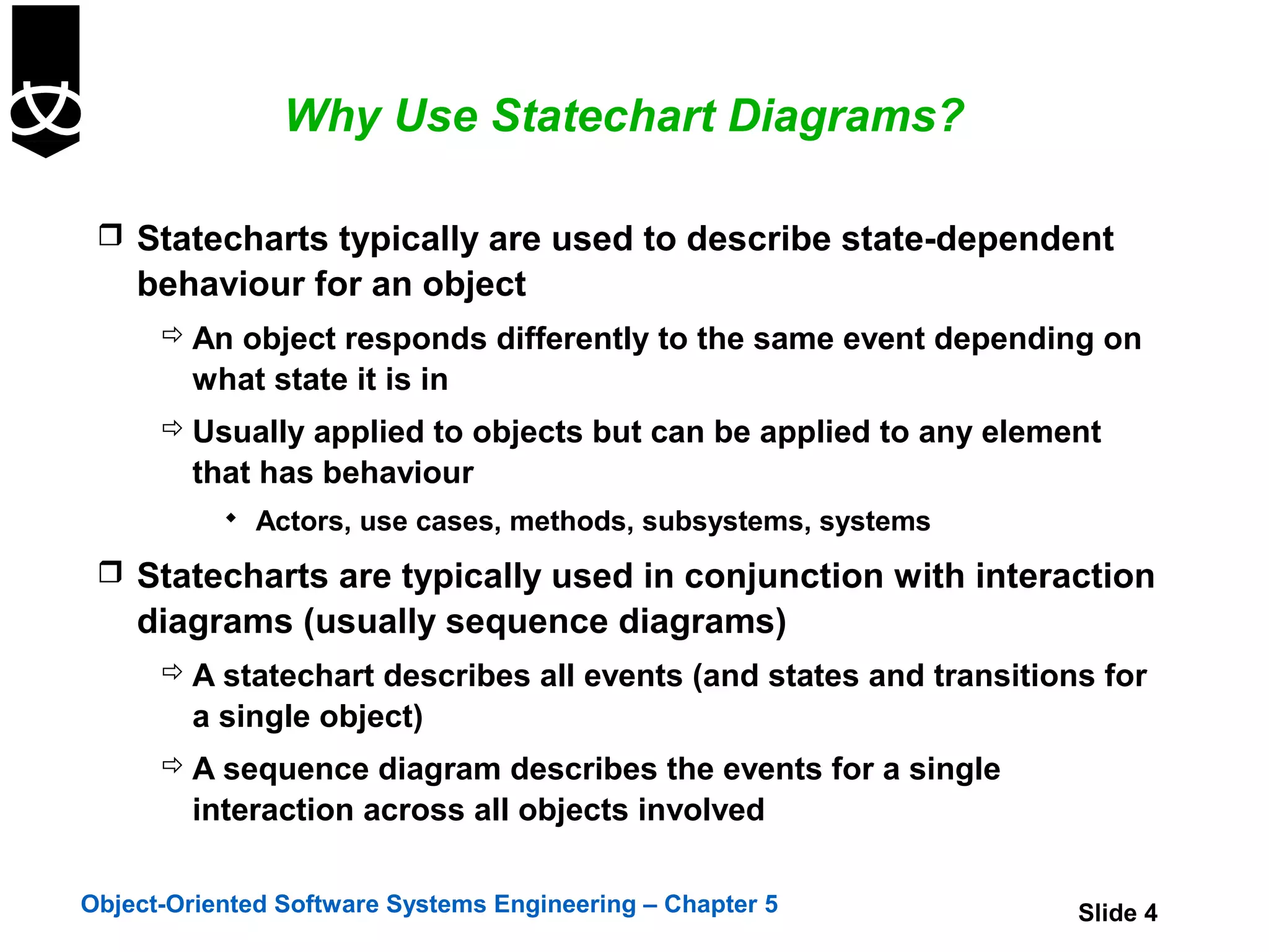

![Transitions
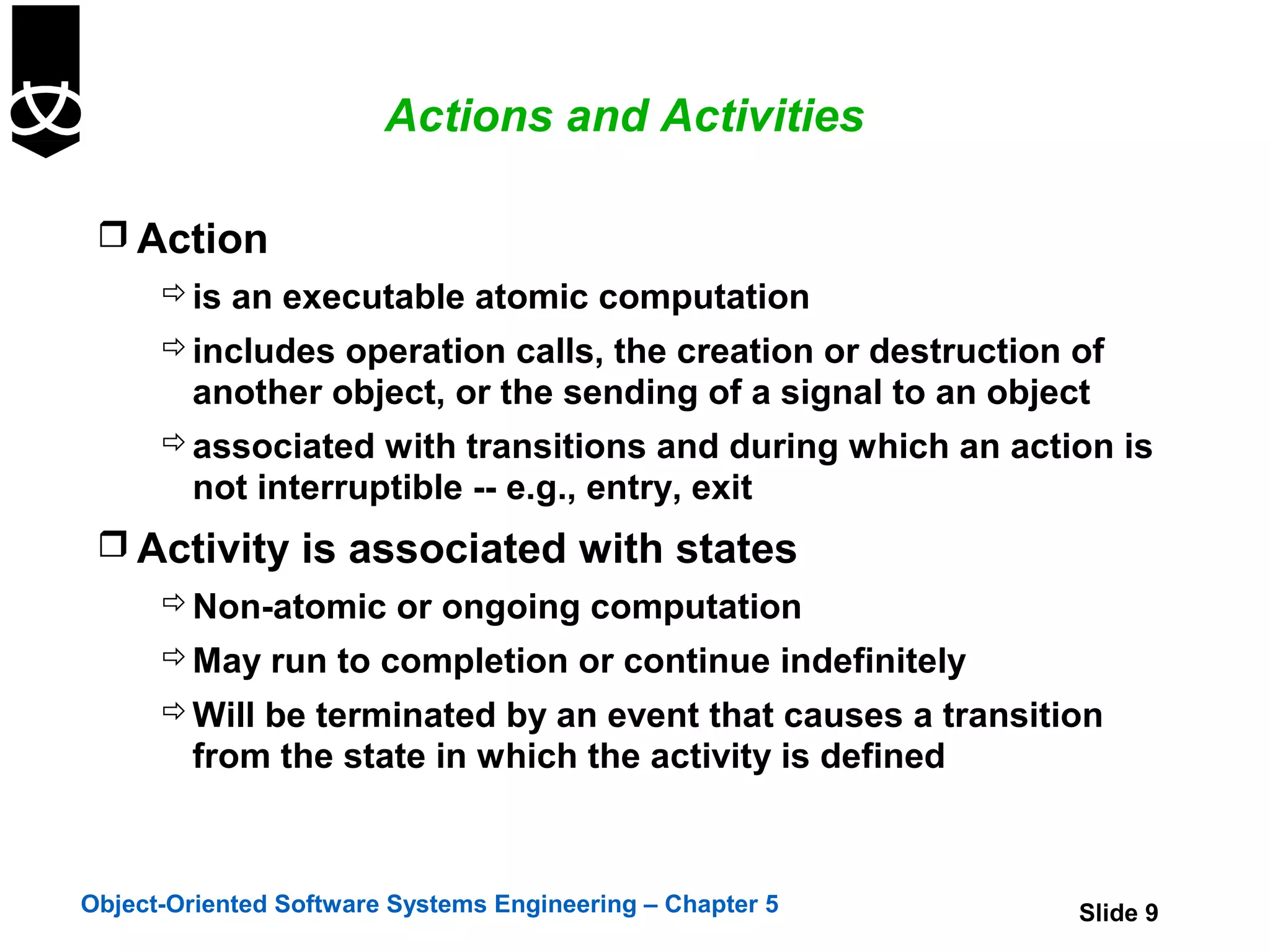
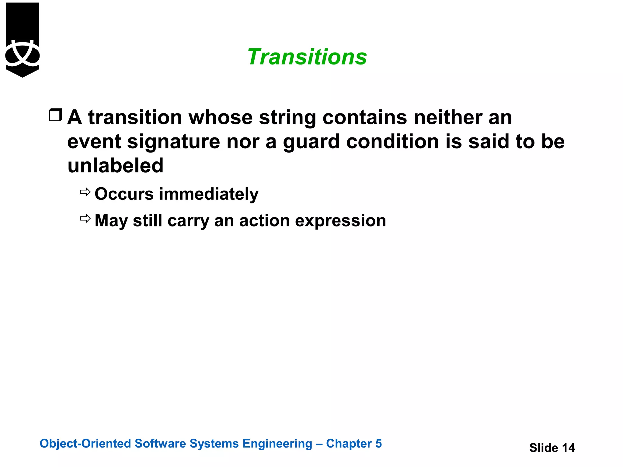
A transition is drawn as an arrow between states
annotated with a transition string
The transition string denotes the event and
consequent action
Only one form of arrowhead is used on statecharts
The distinction between call events and signal events must be
deducted from elsewhere e.g. an interaction diagram
A transition string is described as
Event-signature [guard-condition]/action-expression^object.message
If the guard condition is met the transition occurs immediately
Object-Oriented Software Systems Engineering – Chapter 5 Slide 13](https://image.slidesharecdn.com/5-statediagrams-121220200630-phpapp02/75/5-state-diagrams-13-2048.jpg)
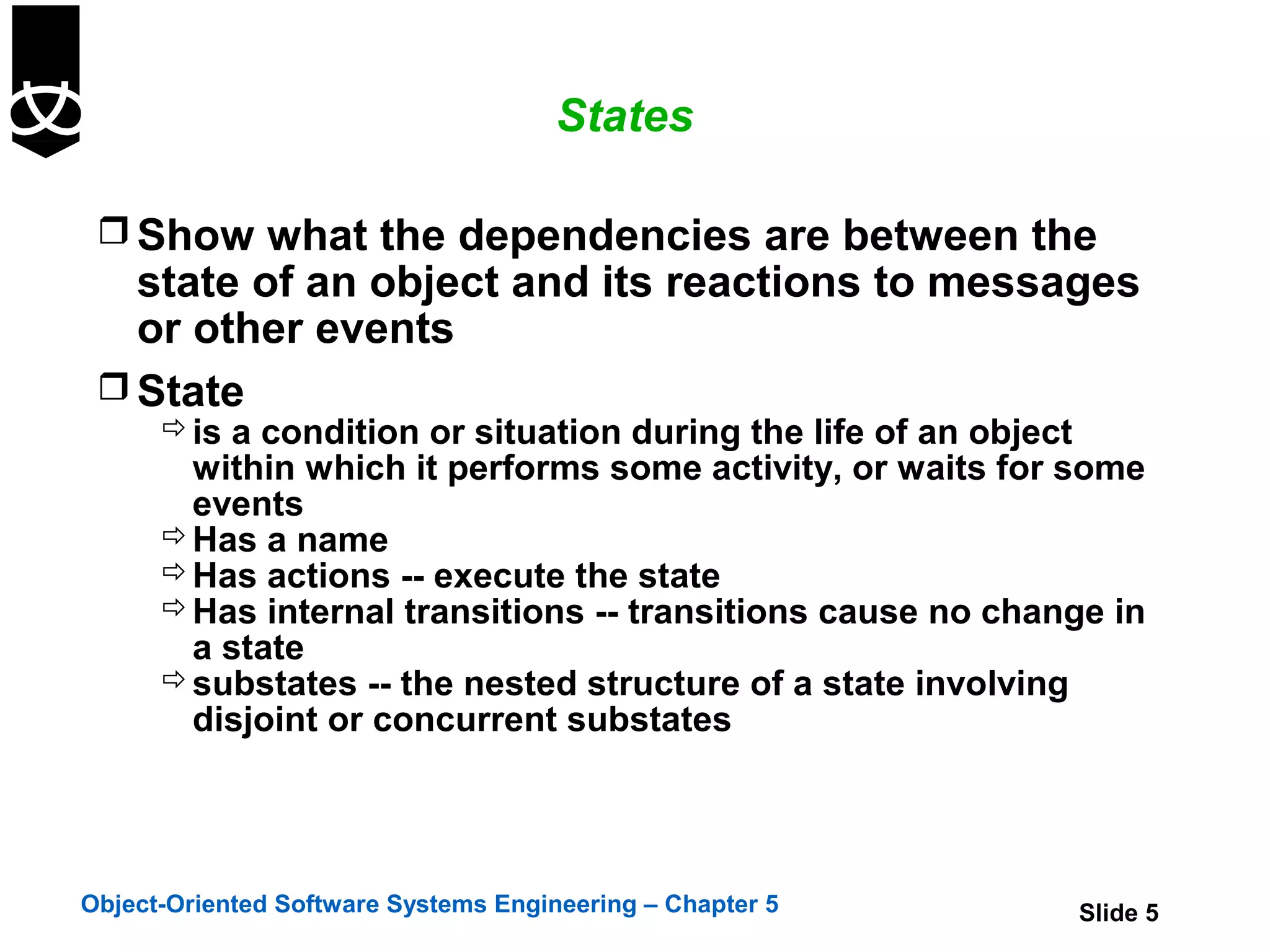
![State Diagram Example
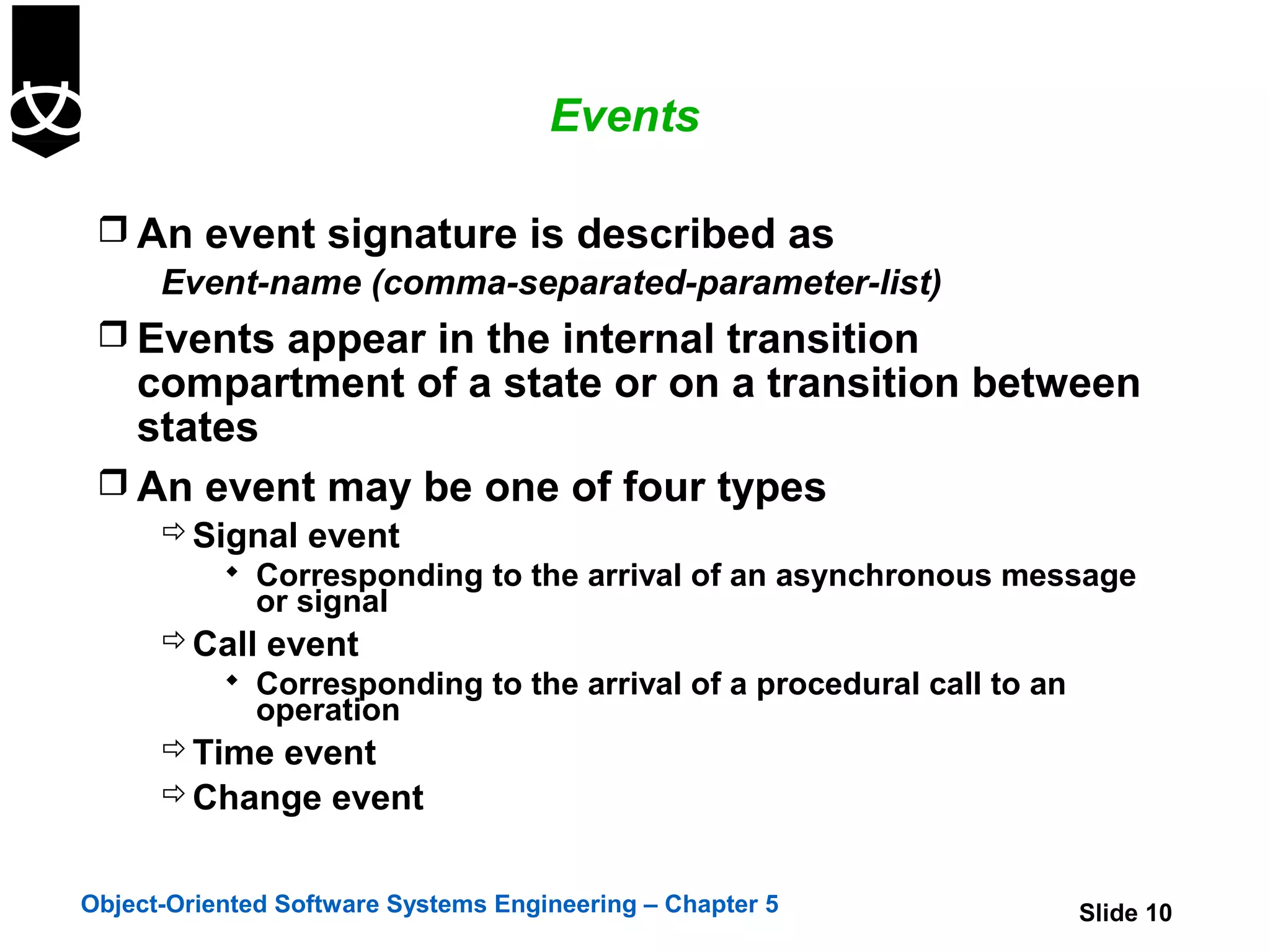
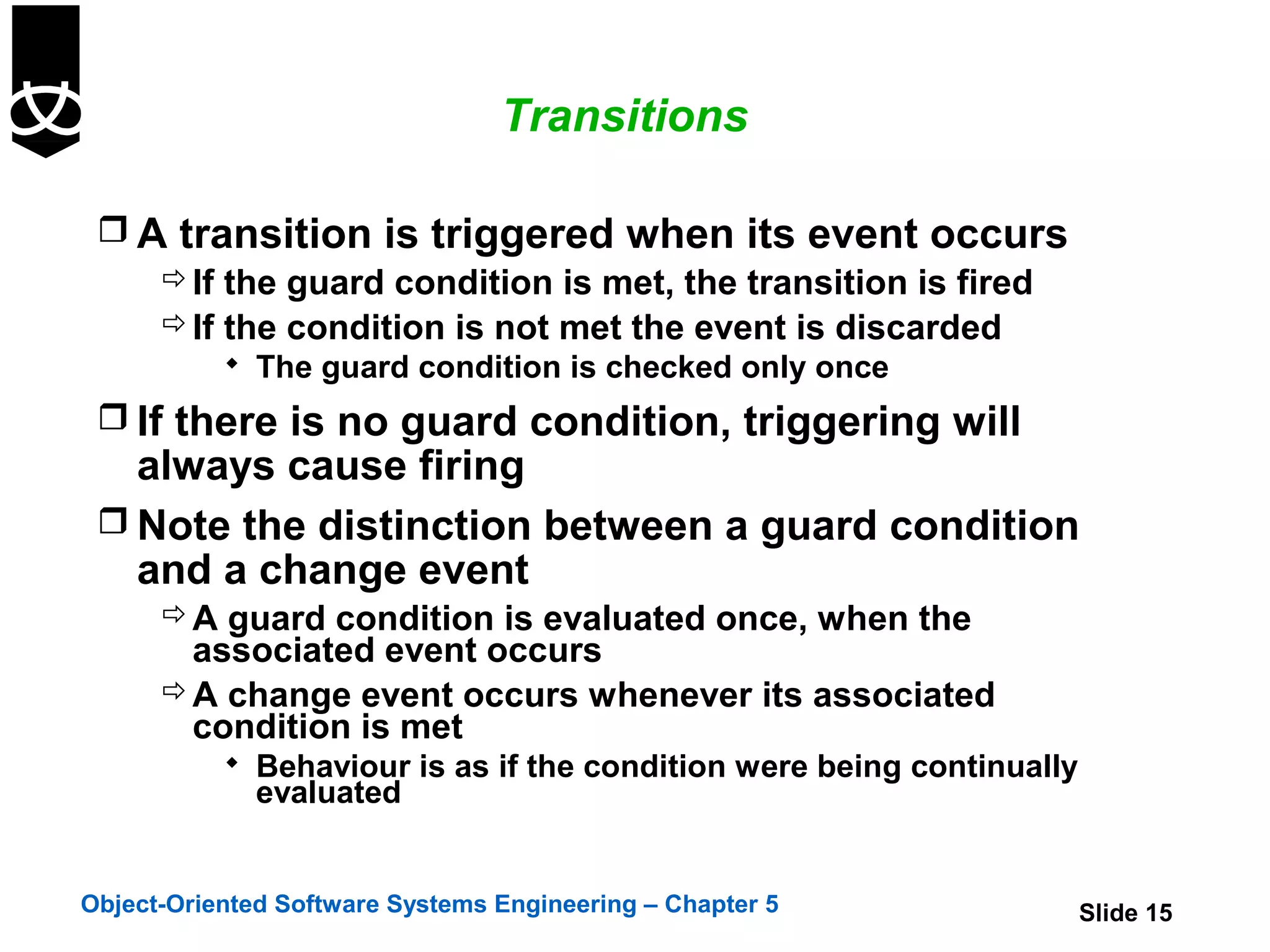
get first item all items
in stock
[all items checked &&
*[all items checked]
all items available]
get next item Checking Dispatching
Dispatch items
do / check
Item
b le] do / initiate
[all items checked aila delivery
av d
&& some items not
tems eive
in stock] ll i rec
[a m delivery
Order Item Ite
some items Ordering Delivering
not in stock cancelled
Exit/ Item received entry / deliver
do / order Item Items
Canceling
do / Remove
Item
Object-Oriented Software Systems Engineering – Chapter 5 Slide 19](https://image.slidesharecdn.com/5-statediagrams-121220200630-phpapp02/75/5-state-diagrams-19-2048.jpg)
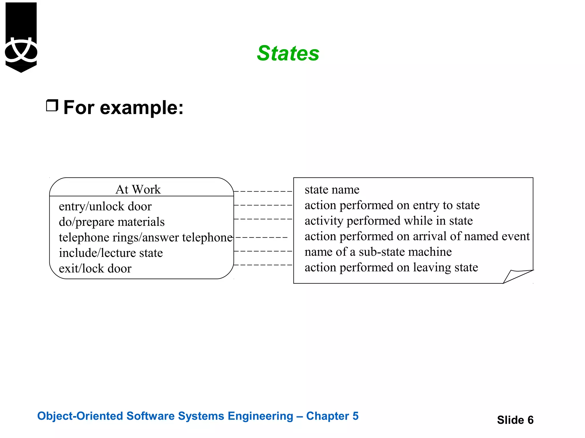
![State Diagram Example including substates
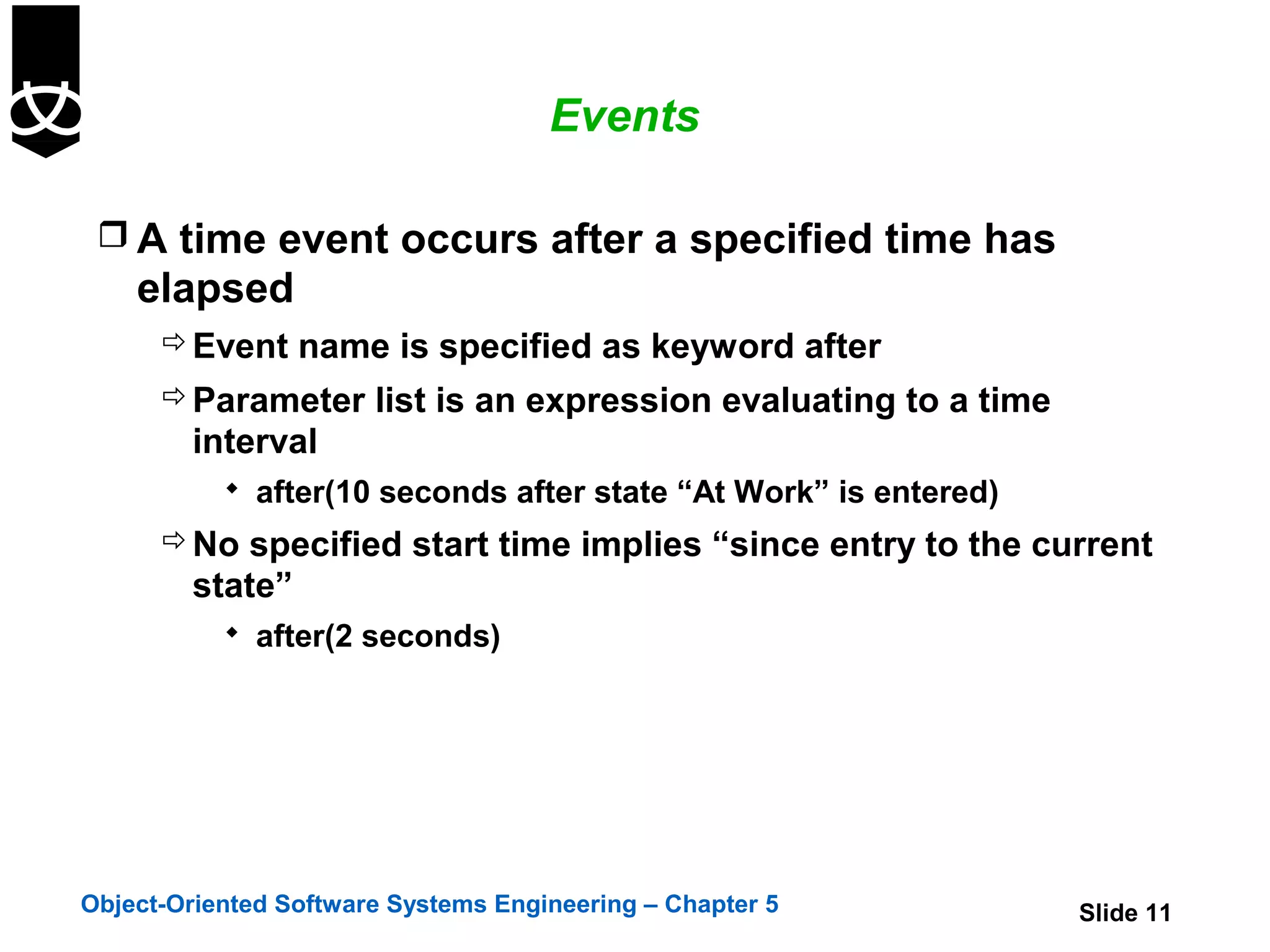
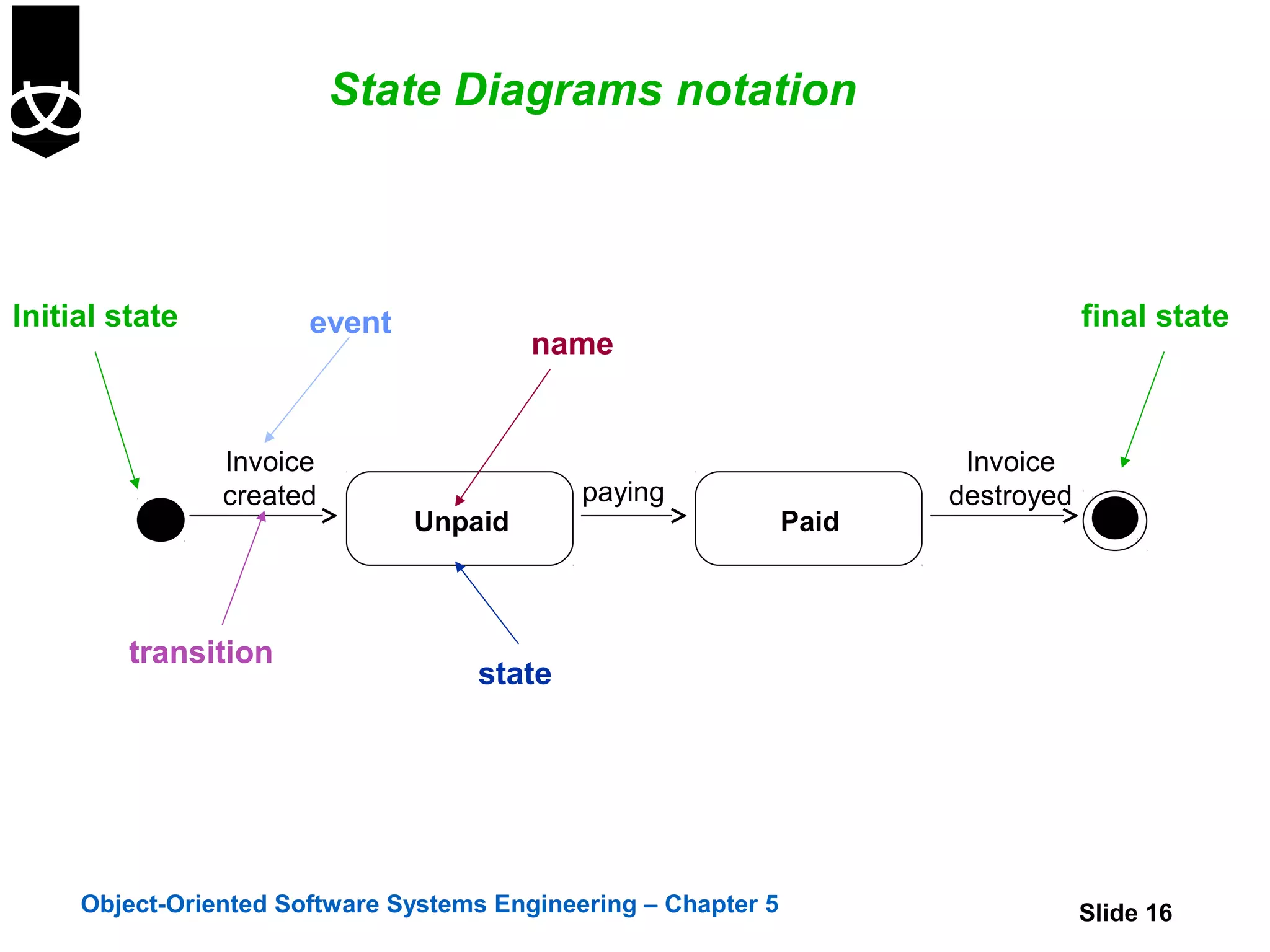
get first item
*[all items checked]
[all items checked && all items available]
get next item
Checking Dispatch items Dispatching
do / check do / initiate
Item ble] delivery
a
v ail
[all items checked && ms a ved
some items not in stock] l ite ecei
Order item [al m r delivery
Ite
Ordering
Exit/ Item received
do / order Item
Canceling Delivering
cancelled
do / Remove entry / deliver
Item Items
Object-Oriented Software Systems Engineering – Chapter 5 Slide 21](https://image.slidesharecdn.com/5-statediagrams-121220200630-phpapp02/75/5-state-diagrams-21-2048.jpg)
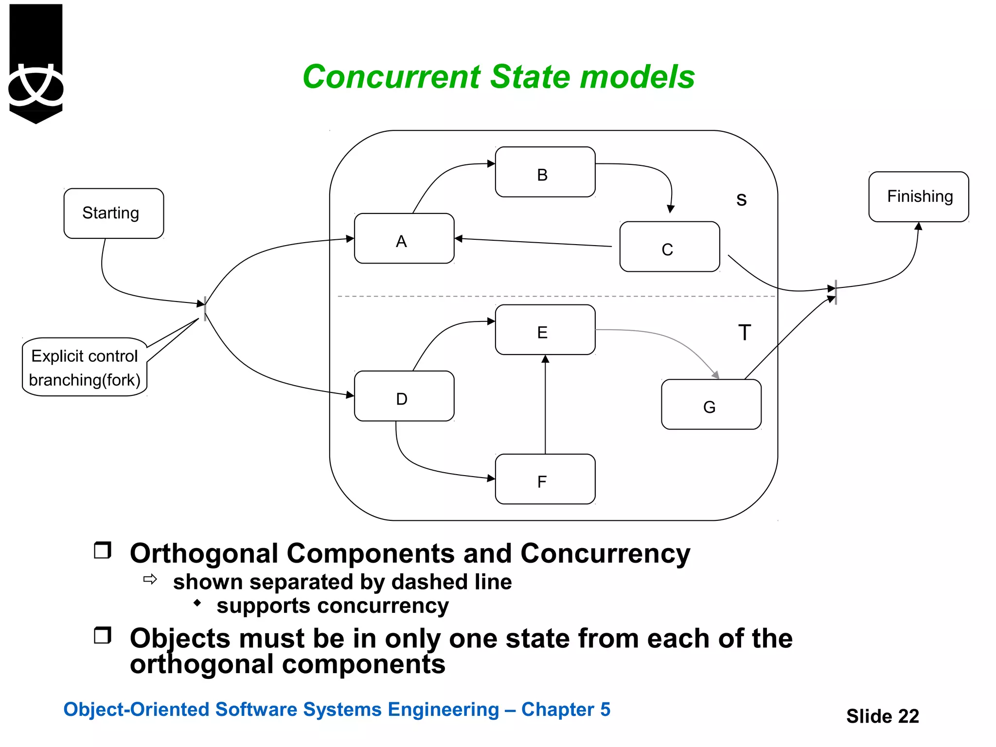
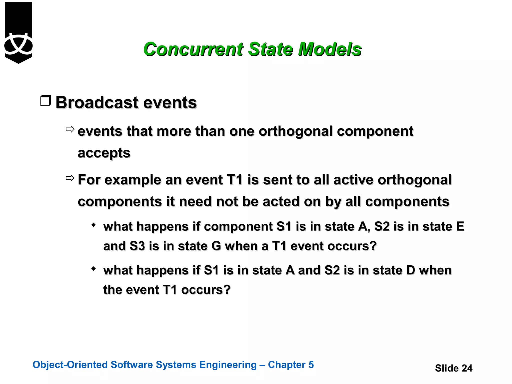
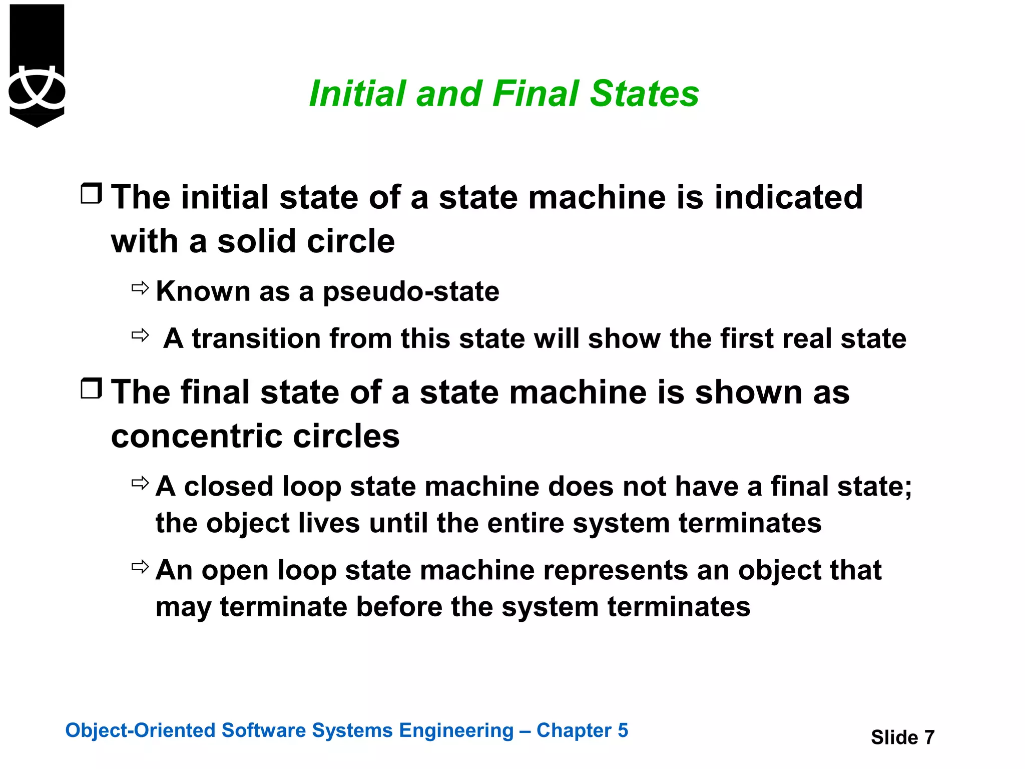
![Concurrent State Models
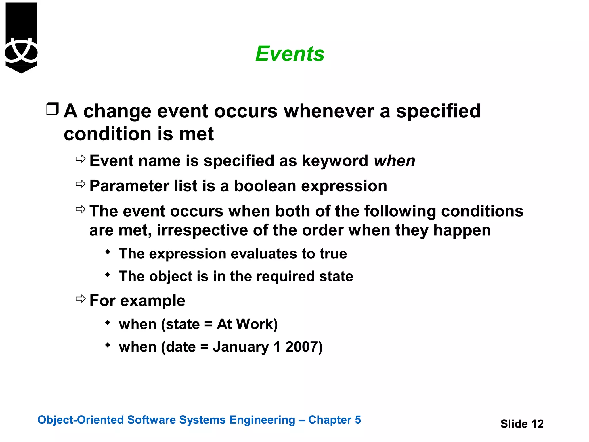
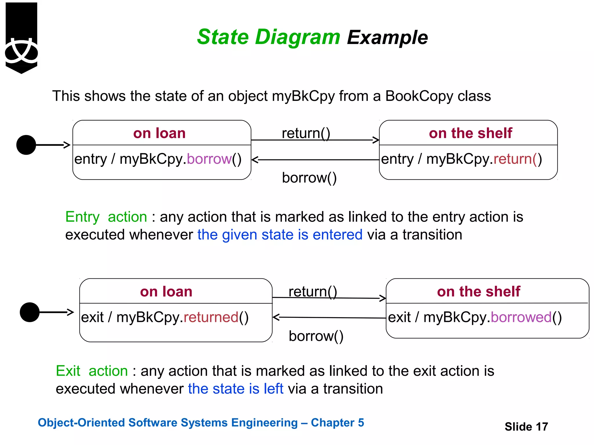
S
S1 H S3
T1
B
F
A
T4[IN(D)]
C
T2^T3(x,y,z) T5
G
S2 H T3(a,b,c)
T6
H
D T3(a,b,c)
T1 E
Object-Oriented Software Systems Engineering – Chapter 5 Slide 26](https://image.slidesharecdn.com/5-statediagrams-121220200630-phpapp02/75/5-state-diagrams-26-2048.jpg)

This chapter introduces state diagrams and their components. It discusses how state diagrams describe the states of an object and transitions between states triggered by events. It covers initial and final states, actions, activities, and different types of events. The chapter also discusses transitions between states and the use of guard conditions. Finally, it introduces concepts like substates, concurrent state diagrams, and ways for orthogonal components to communicate in concurrent state models.