Downloaded 16 times


The document discusses the Unified Modeling Language (UML). UML is a general-purpose modeling language used to specify, visualize, construct, and document software systems. It captures decisions and understanding about systems that must be constructed. The goals of UML included developing a modeling language that could be used across different domains and development methods. UML has three main building blocks - things, relationships, and diagrams. Things represent elements in a model like classes, components, and use cases. Relationships connect things and show dependencies, generalizations, and associations. Diagrams provide different views of UML models, including structural diagrams and behavioral diagrams.
This slide introduces the lecture on Software Engineering II and the presenter, Syed Faraz Ahmad.
UML, a visual modeling language, helps specify, visualize, and document software system artifacts.
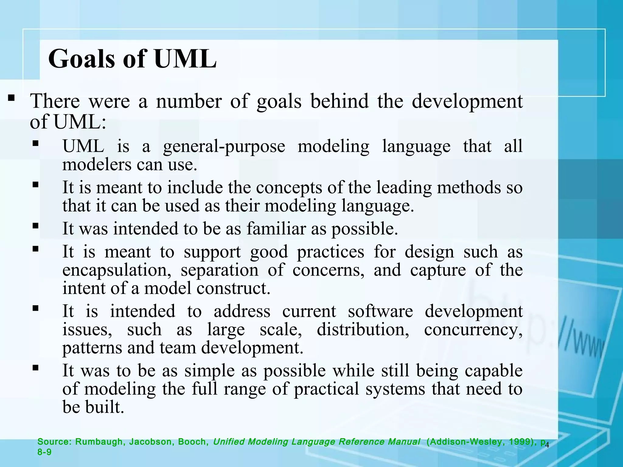
UML aims to be a general-purpose modeling language, supporting good design practices while addressing software development challenges.
UML consists of modeling elements (things), relationships, and diagrams, which are the foundational components of UML models.
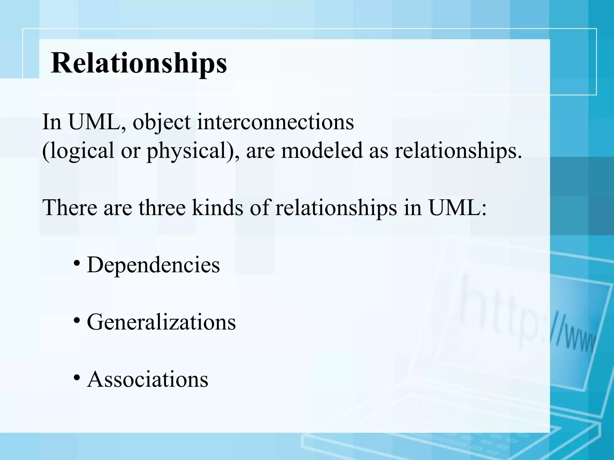
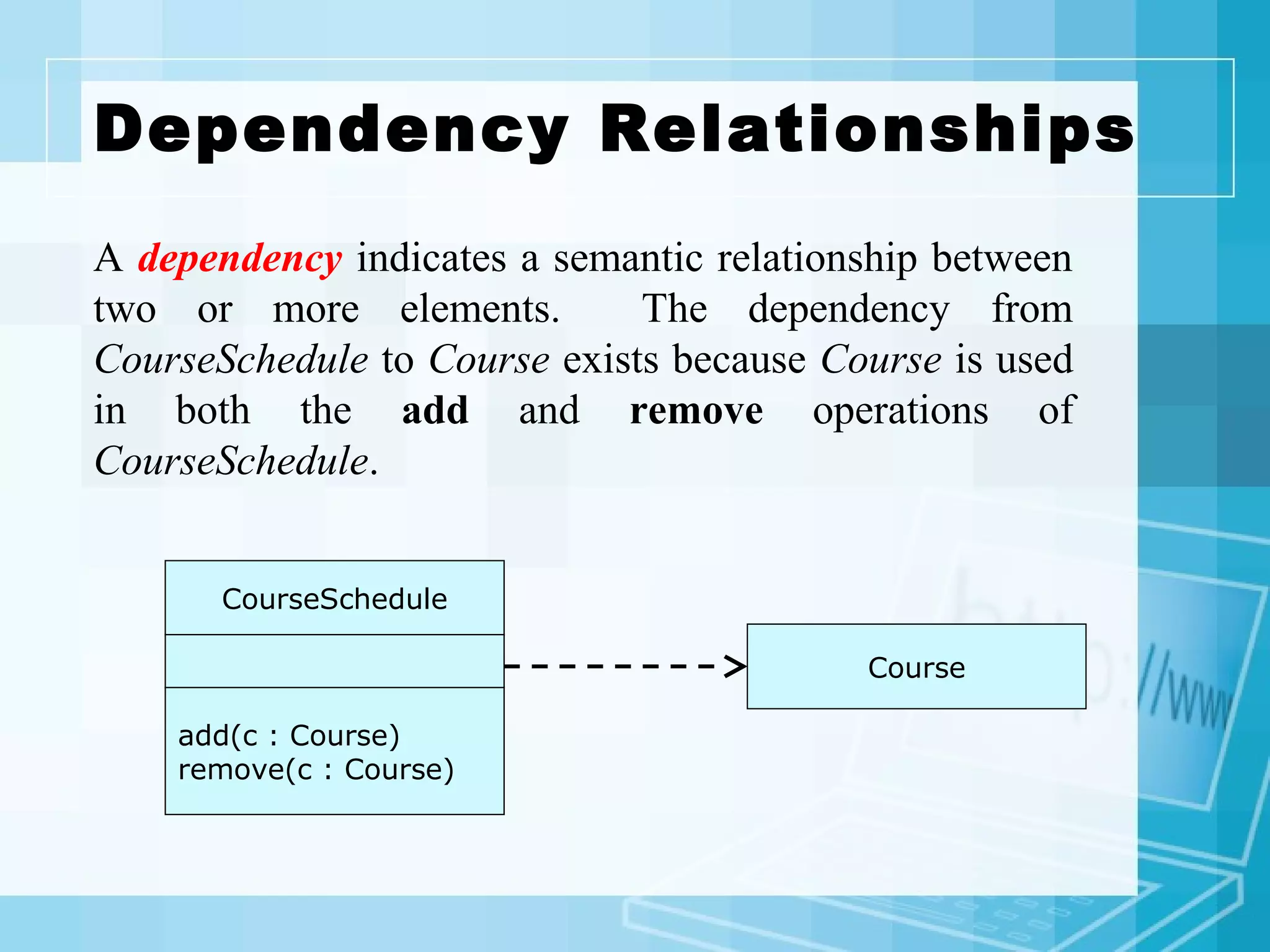
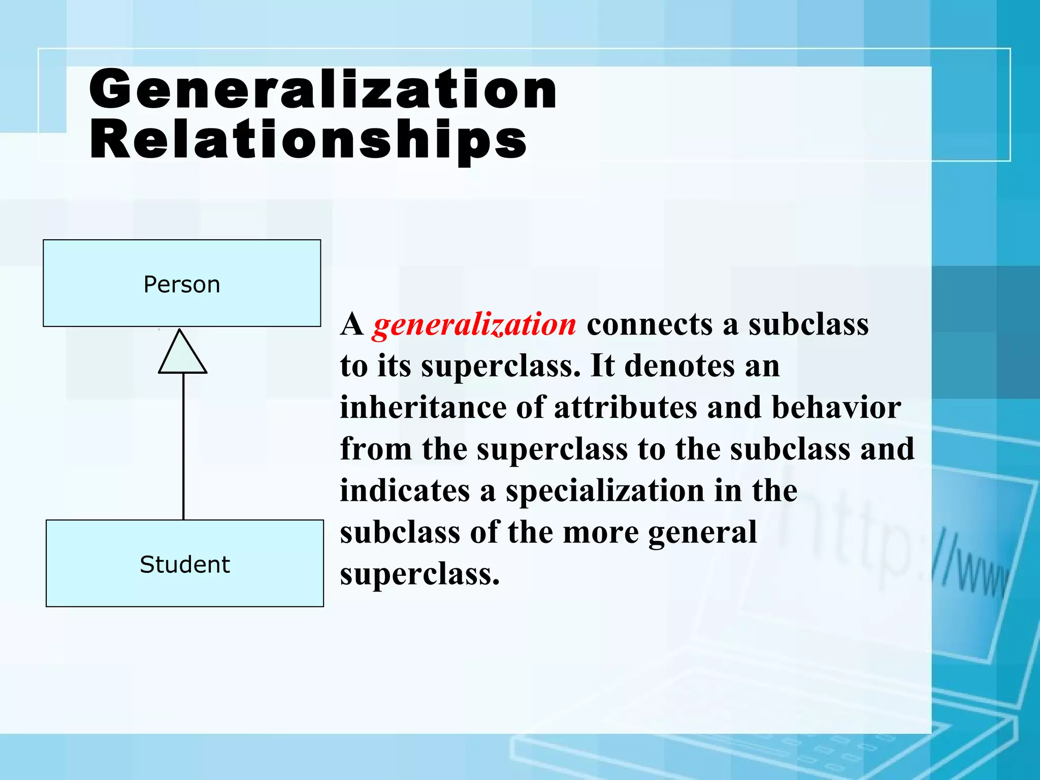
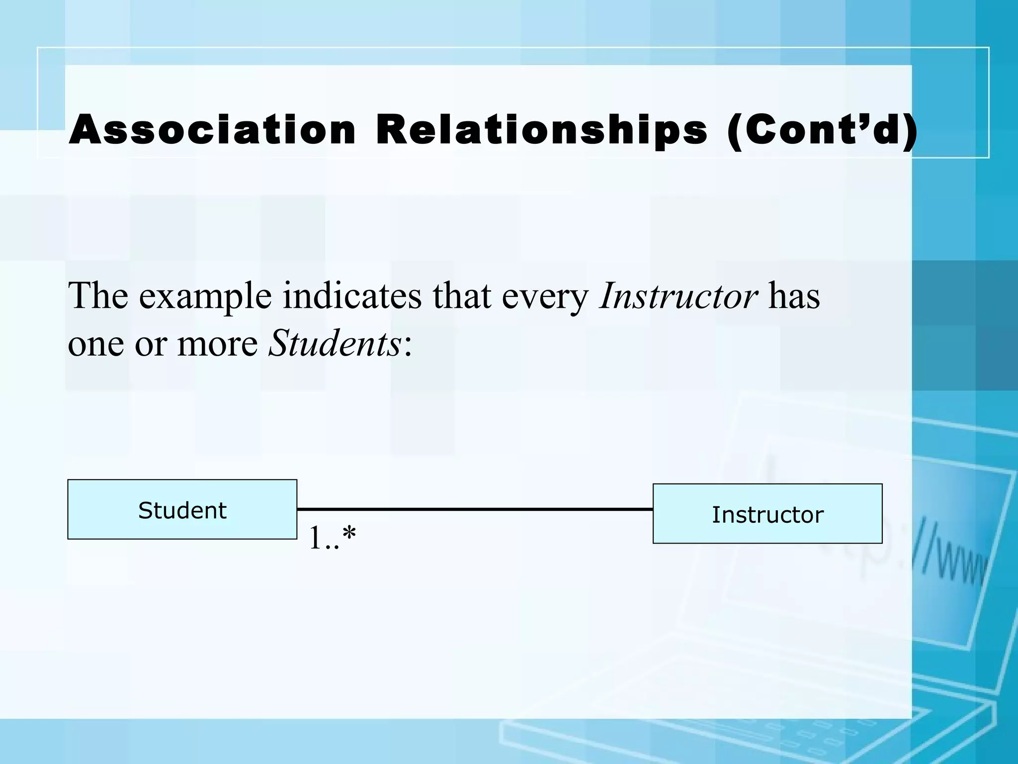
UML features three relationship types: dependencies, generalization, and associations, defining connections between model elements.
Associations link classes for communication; examples illustrate student-instructor interactions showing multiplicity.
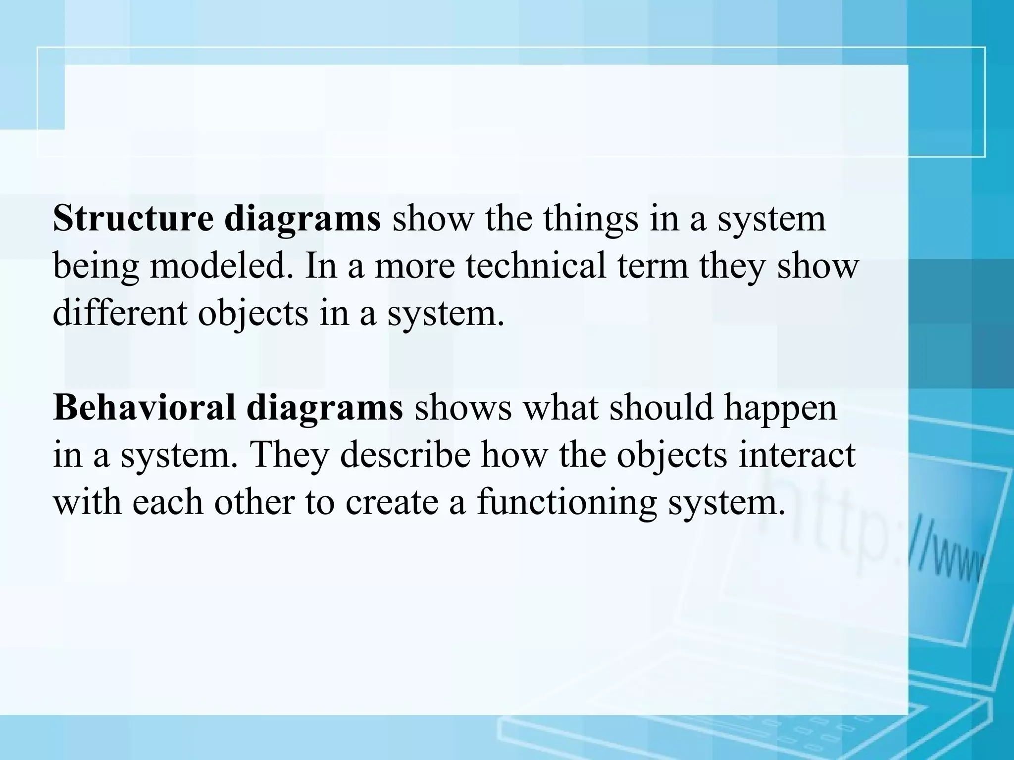
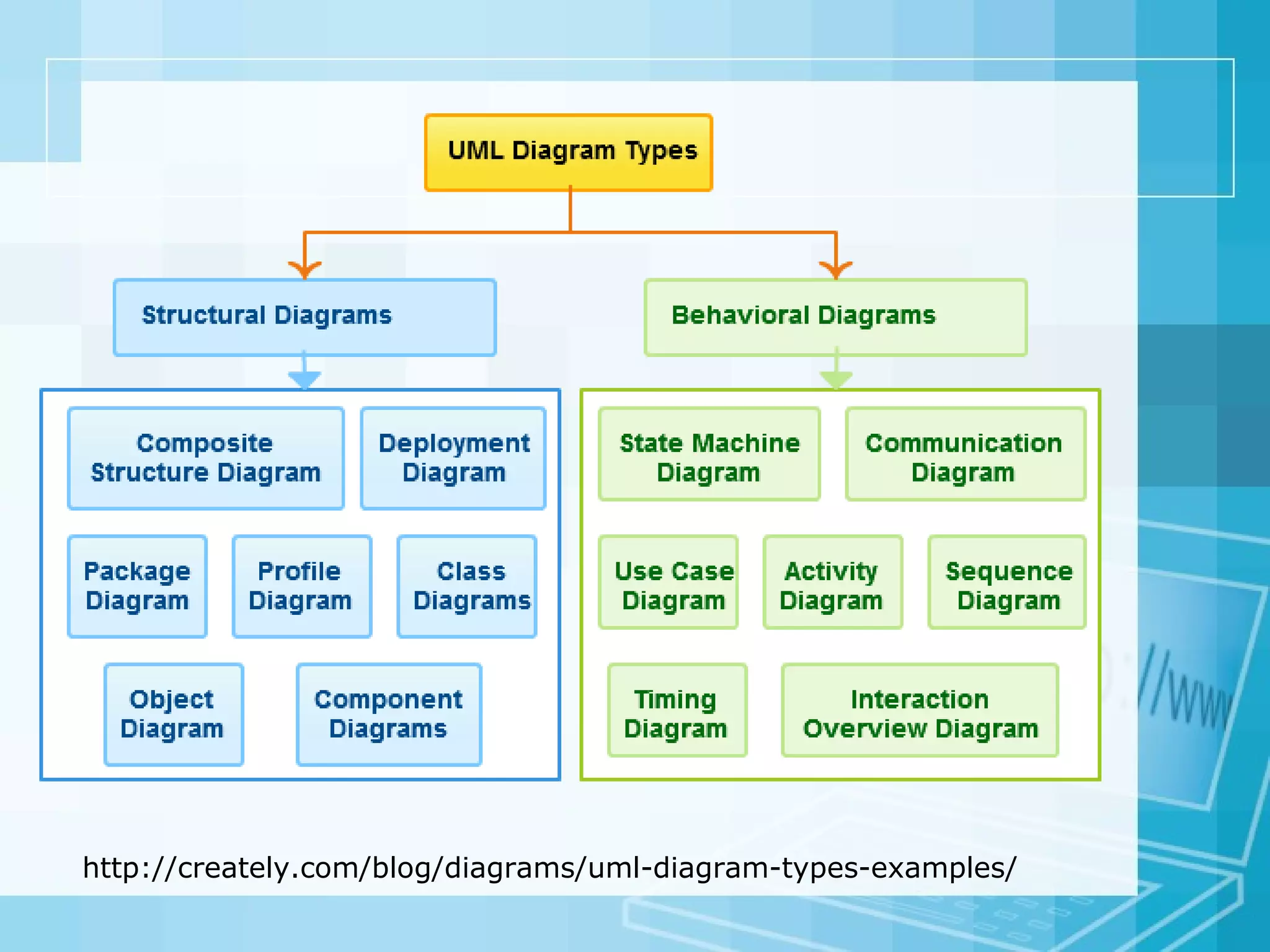
There are 14 UML diagram types, categorized into structure and behavioral diagrams, reflecting system components and behaviors.
Class diagrams represent object-oriented systems, showcasing classes, their attributes, operations, and relationships.
Component diagrams illustrate the structural relationships and interfaces between components in complex software systems.
Object diagrams depict instances of classes at a given time, showing relationships using real-world examples.
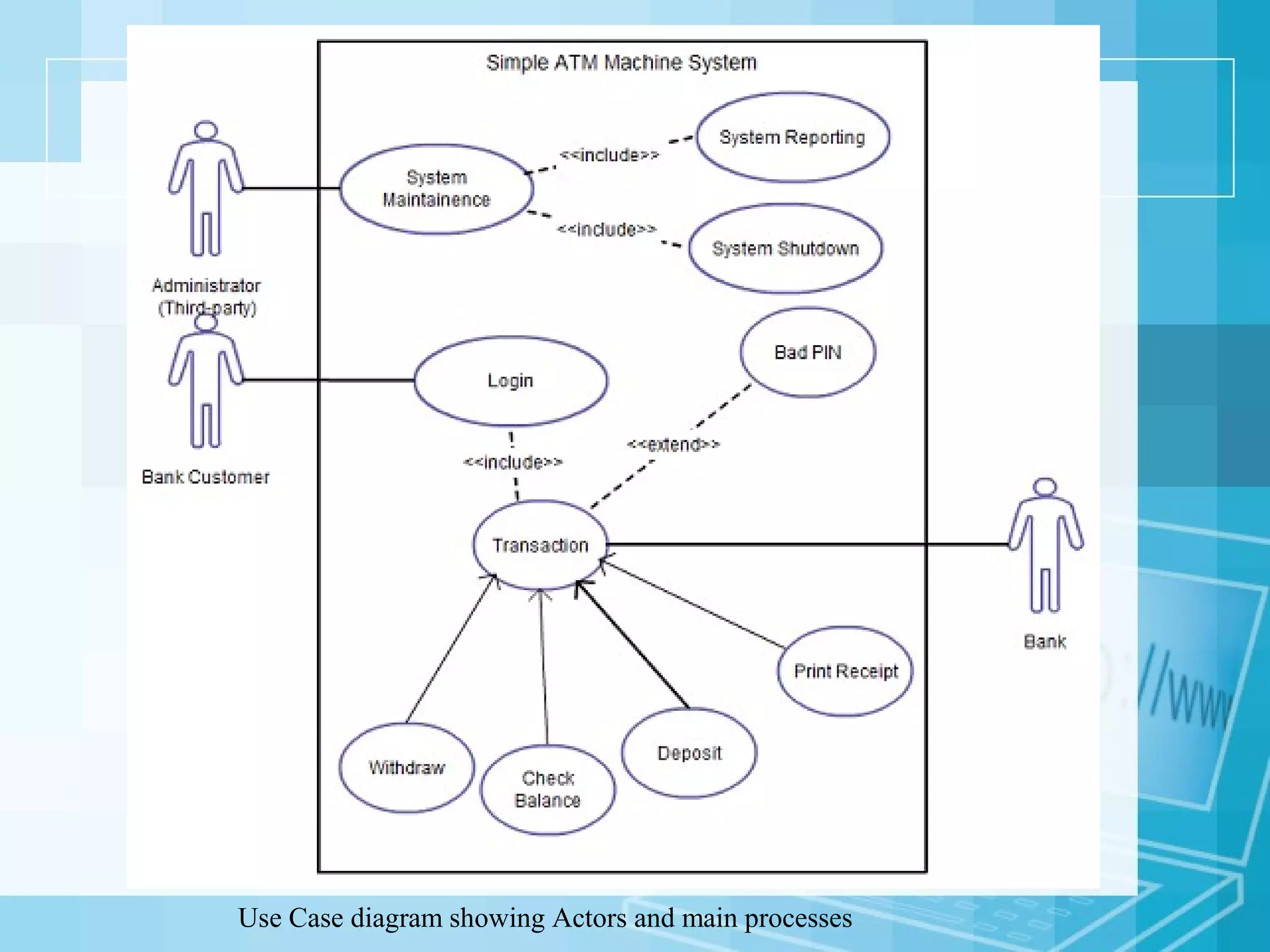
Use case diagrams provide an overview of system actors and functions, serving as a starting point for project discussions.
Activity diagrams graphically represent workflows, useful for describing operational processes and decision points in systems.
Sequence diagrams illustrate object interactions in a particular scenario, detailing the order of those interactions.
Communication diagrams focus on messages passed between objects, similar to sequence diagrams but emphasize message flow.