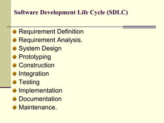
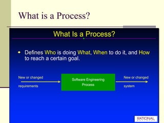
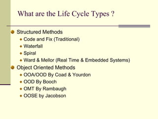
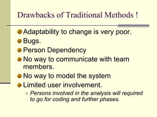
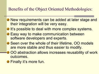
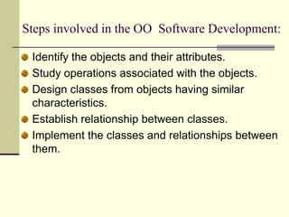
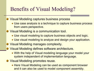
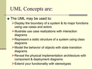
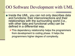
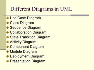
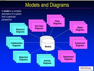
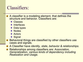
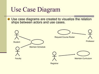
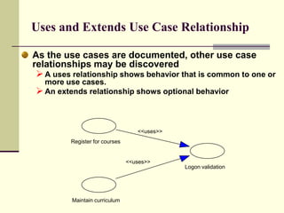
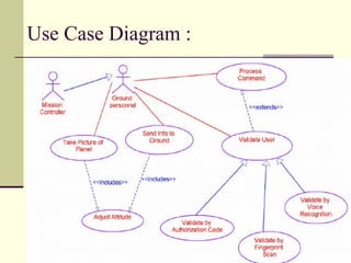
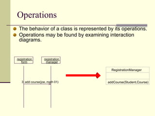
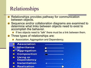
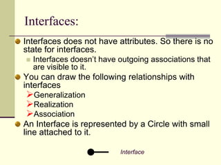
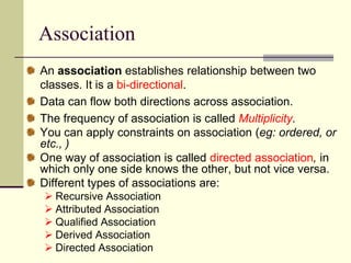
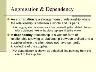
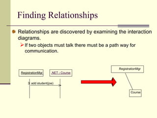
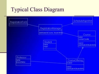
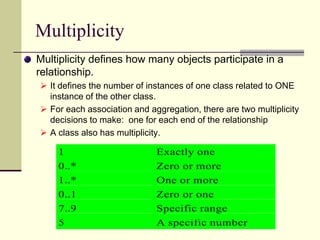
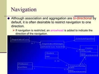
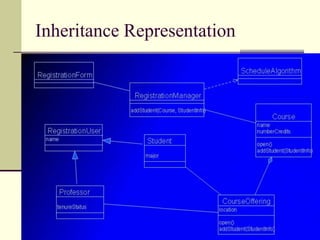
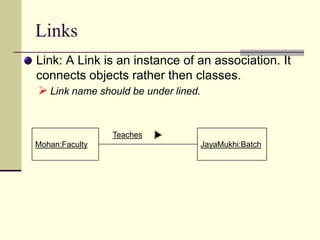
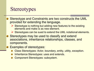
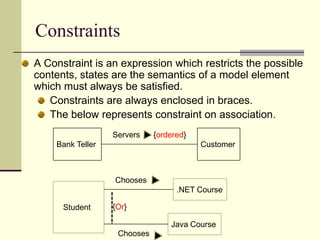
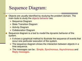
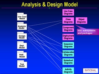
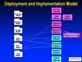
The document discusses UML (Unified Modeling Language) and object-oriented software development. It describes the software development life cycle and various modeling techniques used in UML, including use case diagrams, class diagrams, sequence diagrams, and collaboration diagrams. It explains key UML concepts such as classes, objects, attributes, operations, actors, and relationships. The benefits of visual modeling and UML are also summarized.
UML stands for Unified Modelling Language.
UML is a standard language for specifying, visualizing, constructing, and documenting a system in which software represents the most significant part.
UML is different from the other common programming languages like C++, Java, COBOL etc.
UML is a pictorial language used to make software blue prints.
UML can serve as a central notation for software development process. Using UML helps project teams communicate, explore potential designs, and validate the architectural designs of software.
UML diagrams are made using notation of things and relationships.
The building blocks of UML can be defined as:
Things
Relationships
Diagrams
Things: Things are the most important building blocks of UML. Things can be:
Structural
Behavioral
Grouping
Annotational
The Structural things define the static part of the model. They represent physical and conceptual elements. Following are the brief descriptions of the structural things.
Class: Class represents set of objects having similar responsibilities.
Interface: Interface defines a set of operations which specify the responsibility of a class.
Collaboration: Collaboration defines interaction between elements.
Use case: Use case represents a set of actions performed by a system for a specific goal.
Component: Component describes physical part of a system.
Node: A node can be defined as a physical element that exists at run time.
A behavioral thing consists of the dynamic parts of UML models. Following are the behavioral things:
Interaction: Interaction is defined as a behavior that consists of a group of messages exchanged among elements to accomplish a specific task.
State machine: State machine is useful when the state of an object in its life cycle is important. It defines the sequence of states an object goes through in response to events. Events are external factors responsible for state change.
Unified Modeling Language (UML) is a modeling language, used for design. Designed based on OMG Standard, Object this helps to express and design documents, software. This is particularly useful for OO design. Here is a brief tutorial that talks about UML usage.
This Presentation contains all the topics in design concept of software engineering. This is much more helpful in designing new product. You have to consider some of the design concepts that are given in the ppt
https://www.youtube.com/channel/UChC0cB2n_-n27-STBvGP2NQ
#SURANA_COLLEGE_BENGALURU
Unified Modeling Language (UML) is a general purpose modelling language. The main aim of UML is to define a standard way to visualize the way a system has been designed. It is quite similar to blueprints used in other fields of engineering.
UML is not a programming language, it is rather a visual language. We use UML diagrams to portray the behavior and structure of a system. UML helps software engineers, businessmen and system architects with modelling, design and analysis. The Object Management Group (OMG) adopted Unified Modelling Language as a standard in 1997. Its been managed by OMG ever since. International Organization for Standardization (ISO) published UML as an approved standard in 2005. UML has been revised over the years and is reviewed periodically.
1. UML U M L(Unified Modeling Language)BYCh. Vishwa MohanProject ManagerVision Krest Embedded Systems
2. Software Development Life Cycle (SDLC) Requirement Definition Requirement Analysis. System Design Prototyping Construction Integration Testing Implementation Documentation Maintenance.
4. What are the Life Cycle Types ? Structured Methods Code and Fix (Traditional) Waterfall Spiral Ward & Mellor (Real Time & Embedded Systems) Object Oriented Methods OOA/OOD By Coad & Yourdon OOD By Booch OMT By Rambaugh OOSE by Jacobson
5. Drawbacks of Traditional Methods ! Adaptability to change is very poor. Bugs. Person Dependency No way to communicate with team members. No way to model the system Limited user involvement. Persons involved in the analysis will required to go for coding and further phases.
6. Benefits of the Object Oriented Methodologies: New requirements can be added at later stage and their integration will be very easy. It’s possible to deal with more complex systems. Easy way to make communication between software developers and experts. Seen over the whole of their lifetime, OO models are more stable and thus easier to modify. OO abstraction allows increases reusability of work outcomes. Finally it’s more fun.
7. Steps involved in the OO Software Development: Identify the objects and their attributes. Study operations associated with the objects. Design classes from objects having similar characteristics. Establish relationship between classes. Implement the classes and relationships between them.
8. UML What is Model ? Representation in a certain medium of some thing in the same or other medium. A model represents the blueprint of the system. It is an abstract representation of a system. What is In a Model ? Semantics: It captures the classes, associations, states, use cases and messages. Visual Representation: How to represent model elements. Different tool vendors shows different representation for the same model.
9. What is UML ? UML is a general purpose visual modeling language that is used to specify, visualize, construct, and document the artifacts of a software intensive system. UML enables system builders to create blue prints that capture their vision in a standard easy-to understand way and communication them to others. UML can be used with all processes, throughout the development life cycle, and across different implementation technologies. UML captures the static and dynamic behavior of systems.
10. What is a Visual Modeling ? Basically, the modeling captures the essential parts of the system. Computer system basically automate business processes. However, it’s not easy to build software systems on time and within budget. Building a complex software system requires blueprint. You don’t construct a building without a blueprint. Visual modeling is the blueprint for software systems. Finally we can say, Visual Modeling is the key to successful software development.
12. Benefits of Visual Modeling? Visual Modeling captures business process Use case analysis is a technique to capture business process from users perspective. Visual Modeling is a communication tool. Use visual modeling to capture business objects and logic. Use visual modeling to analyze and design your application. Visual Modeling manages complexity. Visual Modeling defines software architecture. With the help of Visual modeling language your model your system independent of implementation language. Visual Modeling promotes reuse. Here Visual Modeling can be used as component browser and it can also be used to model component assembly.
17. Reveal the physical implementation architecture with component & deployment diagrams
18.
19. Different Diagrams in UML Use Case Diagram Class Diagram Sequence Diagram Collaboration Diagram State Transition Diagram Activity Diagram Component Diagram Module Diagram Deployment Diagram. Presentation Diagram
20.
21.
22. Static View is the foundation of UML. It captures the object Structure. It doesn’t contains details of dynamic behavior.
27. Actor Registrar Faculty Student Billing System An actor is someone or some thing that must interact with the system under development. An Actor is a stereo type of class. An actor is represented with a sticky man.
42. Attributes CourseOffering number loation time The structure of a class is represented by its attributes. Attributes may be found by examining class definitions, the problem requirements, and by applying domain knowledge. Each course offering has a number, location and time
43. Operations registration registration form manager RegistrationManager 3: add course(joe, math 01) addCourse(Student,Course) The behavior of a class is represented by its operations. Operations may be found by examining interaction diagrams.
44. Relationships Relationships provides pathway for communication between objects. Sequence and/or collaboration diagrams are examined to determine what links between objects need to exist to accomplish the behavior. If two objects need to “talk” there must be a link between them. Three types of relationships are: Association, Aggregation and Dependency.
62. Stereotypes can be sued to extend the UML notational elements. Stereotypes may be used to classify and extend associations, inheritance relationships, classes, and components. Examples of stereotypes: Class Stereotypes: Actor, boundary, entity, utility, exception. Inheritance Stereotypes: uses and extends. Component Stereotypes: subsystem.
63. Constraints A Constraint is an expression which restricts the possible contents, states are the semantics of a model element which must always be satisfied. Constraints are always enclosed in braces. The below represents constraint on association. Bank Teller Customer Servers {ordered} Chooses .NET Course Student {Or} Java Course Chooses
70. Sequence Diagram registration registration math 101 math 101 : Student form manager section 1 1: fill in info 2: submit 3: add course(joe, math 01) 4: are you open? 5: are you open? 6: add (joe) 7: add (joe) A Sequence diagram displays the object interaction arranged in a time sequence.
82. Deployment Diagram Registration Database Main Library Building Dorm The deployment diagram shows the configuration or run-time processing elements and the software processes living on them. The deployment diagram visualizes the distribution of components across the enterprise.
Sequential:Only one call to an instance may be outstanding at once. Guarded: Multiple calls from concurrent threads may occur simultaneously to one instance, but only one is allowed to commence. The others are blocked until the performance of the first operation is complete. (Designers to ensure that deadlocks can’t occur)Concurrent: Multiple calls from concurrent threads may occur simultaneously to one instance on any concurrent operation. All of them may process concurrently with correct semantics. (Inside the method implementation synchronization problems are correctly addressed.)