Downloaded 116 times

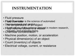
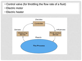
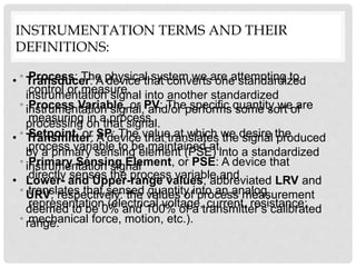
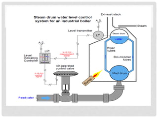
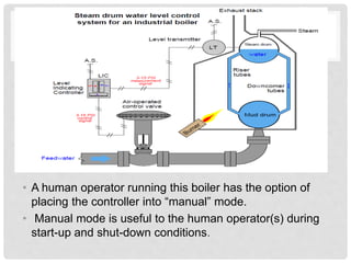
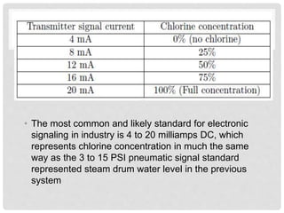
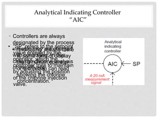
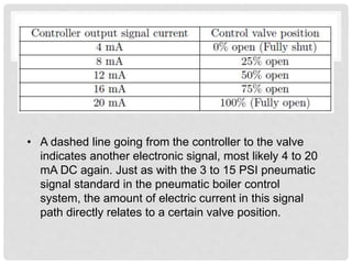
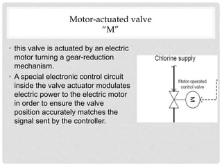


This document introduces industrial instrumentation and provides examples. It defines instrumentation as automated measurement and control that is used in research, industry and everyday life. It then lists common process variables that are measured through instrumentation like pressure, flow rate, temperature and lists common control devices. The rest of the document defines key instrumentation terms and provides two examples - a boiler water level control system using pneumatic signals and a wastewater disinfection system using electronic signals.