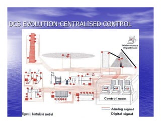
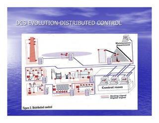
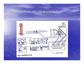
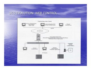
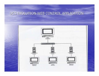
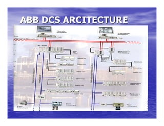
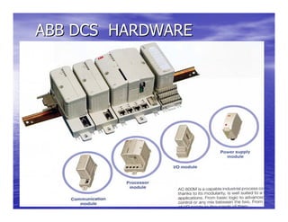
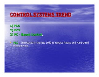
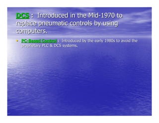
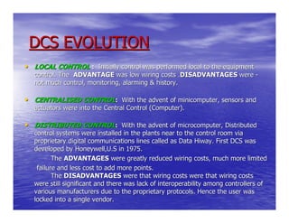
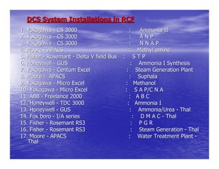
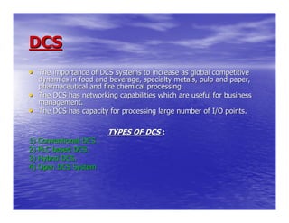
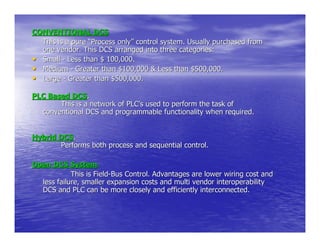
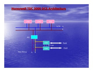
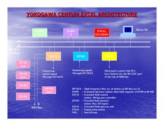
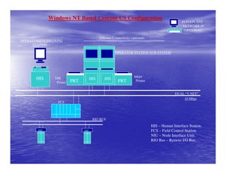
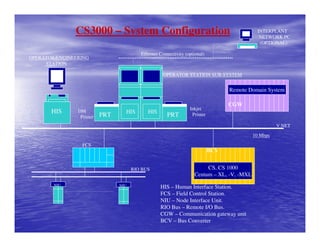
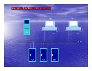
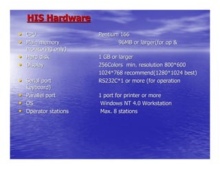
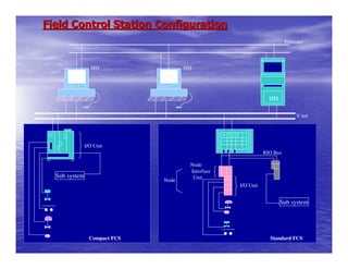
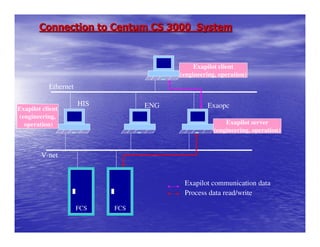
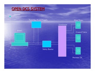
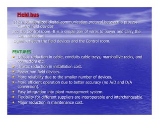
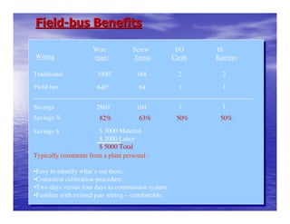
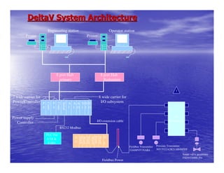
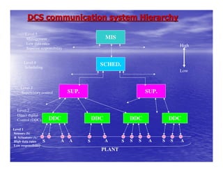
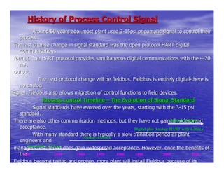
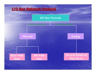
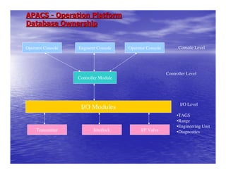
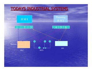
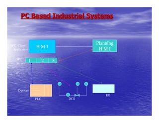
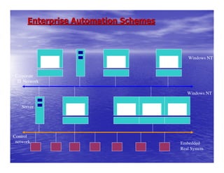
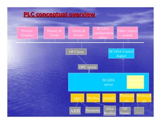
The document discusses control system trends and different distributed control system (DCS) architectures. It describes the evolution of DCS from centralized to distributed control with fieldbus connectivity. It provides examples of DCS installations and components of DCS systems from manufacturers like Honeywell, Yokogawa, and ABB. These include control stations, input/output modules, networks, and the use of Windows-based control.
In this session you will learn:
DCS Introduction
PLC
SCADA
General architecture of DCS
Process or application
Scan time
Input and Output requirement
Redundancy
RTU and LCU
PLC vs DCS
For more information, visit: https://www.mindsmapped.com/courses/industrial-automation/complete-training-on-industrial-automation-for-beginners/
Distributed Control Systems (DCS) are dedicated systems used to control manufacturing processes that are continuous or batch-oriented, such as oil refining, petrochemicals, central station power generation, fertilizers, pharmaceuticals, food and beverage manufacturing, cement production, steelmaking, and papermaking. DCSs are connected to sensors and actuators and use set point control to control the flow of material through the plant.
The most common example is a set point control loop consisting of a pressure sensor, controller, and control valve. Pressure or flow measurements are transmitted to the controller, usually through the aid of a signal conditioning input/output (I/O) device. When the measured variable reaches a certain point, the controller instructs a valve or actuation device to open or close until the fluidic flow process reaches the desired set point.
Large oil refineries have many thousands of I/O points and employ very large DCSs. Processes are not limited to fluidic flow through pipes, however, and can also include things like paper machines and their associated quality controls (see quality control system QCS), variable speed drives and motor control centers, cement kilns, mining operations, ore processing facilities, and many others.
Innovic India Private Limited provides industrial Training on DCS as well as other automationtechnologies like PLC, SCADA, HMI, VFD and many more.
For Core Engineering jobs and 100% Job Oriented Industrial Training
Feel free to contact us on: +91-9555405045/+91-9811253572
Email: group.innovic2gmail.com
Web: www.innovicindia.com
This PPT is based upon my training in Yokogawa Chennai.
Reference:
# Yokogawa Hand Book on CS 3000
# http://www.slideshare.net/bvent2005/dcs-presentation
This presentation is about the Distributed Control system in Power plants. DCS is a computerised control system for a process or plant usually with many control loops, in which autonomous controllers are distributed throughout the system, but there is no central operator supervisory control.
Practical Distributed Control Systems (DCS) for Engineers and TechniciansLiving Online
This workshop will cover the practical applications of the modern Distributed Control System (DCS). Whilst all control systems are distributed to a certain extent today and there is a definite merging of the concepts of a DCS, Programmable Logic Controller (PLC) and SCADA and despite the rapid growth in the use of PLC’s and SCADA systems, some of the advantages of a DCS can still be said to be Integrity and Engineering time.
Abnormal Situation Management and Intelligent Alarm Management is a very important DCS issue that provides significant advantages over PLC and SCADA systems.
Few DCSs do justice to the process in terms of controlling for superior performance – most of them merely do the basics and leave the rest to the operators. Operators tend to operate within their comfort zone; they don’t drive the process “like Vettel drives his Renault”. If more than one adverse condition developed at the same time and the system is too basic to act protectively, the operator would probably not be able to react adequately and risk a major deviation.
Not only is the process control functionality normally underdeveloped but on-line process and control system performance evaluation is rarely seen and alarm management is often badly done. Operators consequently have little feedback on their own performance and exceptional adverse conditions are often not handled as well as they should be. This workshop gives suggestions on dealing with these issues.
The losses in process performance due to the inadequately developed control functionality and the operator’s utilisation of the system are invisible in the conventional plant and process performance evaluation and reporting system; that is why it is so hard to make the case for eliminating these losses. Accounting for the invisible losses due to inferior control is not a simple matter, technically and managerially; so it is rarely attempted. A few suggestions are given in dealing with this.
Why are DCS generally so underutilised? Often because the vendor minimises the applications software development costs to be sure of winning the job, or because he does not know enough about the process or if it is a green-field situation, enough could not be known at commissioning time but no allowance was made to add the missing functionality during the ramp-up phase. Often the client does not have the technical skills in-house to realise the desired functionality is missing or to adequately specify the desired functionality.
This workshop examines all these issues and gives suggestions in dealing with them and whilst not being by any means exhaustive provides an excellent starting point for you in working with a DCS.
MORE INFORMATION: http://www.idc-online.com/content/practical-distributed-control-systems-dcs-engineers-technicians-2
In this session you will learn:
OSI reference model
OSI layers
Modbus communication protocol
Profibus communication protocol
Fieldbus communication protocol
For more information, visit: https://www.mindsmapped.com/courses/industrial-automation/complete-training-on-industrial-automation-for-beginners/
A reference guide to DeltaV DCS controls and operation. This easy, intuitive, and interoperable Distributed
Control System (DCS) harnesses predictive
technologies to connect your people, processes, and
production.
Ls catalog thiet bi tu dong master p 5000-eDien Ha The
Catalog LS, Catalog,
Catalog Thiết Bị Điện LS, Catalog Thiết Bị Điện,
Catalog Biến Tần LS, Catalog Biến Tần,
Catalog Inverter LS, Catalog Inveter,
http://dienhathe.com,
Chi tiết các sản phẩm khác của LS tại https://dienhathe.com
Xem thêm các Catalog khác của LS tại https://dienhathe.info
Để nhận báo giá sản phẩm LS vui lòng gọi: 0907.764.966
Ls catalog thiet bi tu dong master p 5000-e_dienhathe.vnDien Ha The
Khoa Học - Kỹ Thuật & Giải Trí: http://phongvan.org
Tài Liệu Khoa Học Kỹ Thuật: http://tailieukythuat.info
Thiết bị Điện Công Nghiệp - Điện Hạ Thế: http://dienhathe.org
This connection or communication of multiple microcontrollers in a network is to a get a desired output. It is widely used in modern automobile industries. More and more microcontrollers are embedded in different kinds of products from industrial environment to domestic area.
Key Trends Shaping the Future of Infrastructure.pdfCheryl Hung
Keynote at DIGIT West Expo, Glasgow on 29 May 2024.
Cheryl Hung, ochery.com
Sr Director, Infrastructure Ecosystem, Arm.
The key trends across hardware, cloud and open-source; exploring how these areas are likely to mature and develop over the short and long-term, and then considering how organisations can position themselves to adapt and thrive.
Dev Dives: Train smarter, not harder – active learning and UiPath LLMs for do...UiPathCommunity
💥 Speed, accuracy, and scaling – discover the superpowers of GenAI in action with UiPath Document Understanding and Communications Mining™:
See how to accelerate model training and optimize model performance with active learning
Learn about the latest enhancements to out-of-the-box document processing – with little to no training required
Get an exclusive demo of the new family of UiPath LLMs – GenAI models specialized for processing different types of documents and messages
This is a hands-on session specifically designed for automation developers and AI enthusiasts seeking to enhance their knowledge in leveraging the latest intelligent document processing capabilities offered by UiPath.
Speakers:
👨🏫 Andras Palfi, Senior Product Manager, UiPath
👩🏫 Lenka Dulovicova, Product Program Manager, UiPath
Epistemic Interaction - tuning interfaces to provide information for AI supportAlan Dix
Paper presented at SYNERGY workshop at AVI 2024, Genoa, Italy. 3rd June 2024
https://alandix.com/academic/papers/synergy2024-epistemic/
As machine learning integrates deeper into human-computer interactions, the concept of epistemic interaction emerges, aiming to refine these interactions to enhance system adaptability. This approach encourages minor, intentional adjustments in user behaviour to enrich the data available for system learning. This paper introduces epistemic interaction within the context of human-system communication, illustrating how deliberate interaction design can improve system understanding and adaptation. Through concrete examples, we demonstrate the potential of epistemic interaction to significantly advance human-computer interaction by leveraging intuitive human communication strategies to inform system design and functionality, offering a novel pathway for enriching user-system engagements.
The Art of the Pitch: WordPress Relationships and SalesLaura Byrne
Clients don’t know what they don’t know. What web solutions are right for them? How does WordPress come into the picture? How do you make sure you understand scope and timeline? What do you do if sometime changes?
All these questions and more will be explored as we talk about matching clients’ needs with what your agency offers without pulling teeth or pulling your hair out. Practical tips, and strategies for successful relationship building that leads to closing the deal.
PHP Frameworks: I want to break free (IPC Berlin 2024)Ralf Eggert
In this presentation, we examine the challenges and limitations of relying too heavily on PHP frameworks in web development. We discuss the history of PHP and its frameworks to understand how this dependence has evolved. The focus will be on providing concrete tips and strategies to reduce reliance on these frameworks, based on real-world examples and practical considerations. The goal is to equip developers with the skills and knowledge to create more flexible and future-proof web applications. We'll explore the importance of maintaining autonomy in a rapidly changing tech landscape and how to make informed decisions in PHP development.
This talk is aimed at encouraging a more independent approach to using PHP frameworks, moving towards a more flexible and future-proof approach to PHP development.
Builder.ai Founder Sachin Dev Duggal's Strategic Approach to Create an Innova...Ramesh Iyer
In today's fast-changing business world, Companies that adapt and embrace new ideas often need help to keep up with the competition. However, fostering a culture of innovation takes much work. It takes vision, leadership and willingness to take risks in the right proportion. Sachin Dev Duggal, co-founder of Builder.ai, has perfected the art of this balance, creating a company culture where creativity and growth are nurtured at each stage.
Essentials of Automations: Optimizing FME Workflows with ParametersSafe Software
Are you looking to streamline your workflows and boost your projects’ efficiency? Do you find yourself searching for ways to add flexibility and control over your FME workflows? If so, you’re in the right place.
Join us for an insightful dive into the world of FME parameters, a critical element in optimizing workflow efficiency. This webinar marks the beginning of our three-part “Essentials of Automation” series. This first webinar is designed to equip you with the knowledge and skills to utilize parameters effectively: enhancing the flexibility, maintainability, and user control of your FME projects.
Here’s what you’ll gain:
- Essentials of FME Parameters: Understand the pivotal role of parameters, including Reader/Writer, Transformer, User, and FME Flow categories. Discover how they are the key to unlocking automation and optimization within your workflows.
- Practical Applications in FME Form: Delve into key user parameter types including choice, connections, and file URLs. Allow users to control how a workflow runs, making your workflows more reusable. Learn to import values and deliver the best user experience for your workflows while enhancing accuracy.
- Optimization Strategies in FME Flow: Explore the creation and strategic deployment of parameters in FME Flow, including the use of deployment and geometry parameters, to maximize workflow efficiency.
- Pro Tips for Success: Gain insights on parameterizing connections and leveraging new features like Conditional Visibility for clarity and simplicity.
We’ll wrap up with a glimpse into future webinars, followed by a Q&A session to address your specific questions surrounding this topic.
Don’t miss this opportunity to elevate your FME expertise and drive your projects to new heights of efficiency.
Transcript: Selling digital books in 2024: Insights from industry leaders - T...BookNet Canada
The publishing industry has been selling digital audiobooks and ebooks for over a decade and has found its groove. What’s changed? What has stayed the same? Where do we go from here? Join a group of leading sales peers from across the industry for a conversation about the lessons learned since the popularization of digital books, best practices, digital book supply chain management, and more.
Link to video recording: https://bnctechforum.ca/sessions/selling-digital-books-in-2024-insights-from-industry-leaders/
Presented by BookNet Canada on May 28, 2024, with support from the Department of Canadian Heritage.
GDG Cloud Southlake #33: Boule & Rebala: Effective AppSec in SDLC using Deplo...James Anderson
Effective Application Security in Software Delivery lifecycle using Deployment Firewall and DBOM
The modern software delivery process (or the CI/CD process) includes many tools, distributed teams, open-source code, and cloud platforms. Constant focus on speed to release software to market, along with the traditional slow and manual security checks has caused gaps in continuous security as an important piece in the software supply chain. Today organizations feel more susceptible to external and internal cyber threats due to the vast attack surface in their applications supply chain and the lack of end-to-end governance and risk management.
The software team must secure its software delivery process to avoid vulnerability and security breaches. This needs to be achieved with existing tool chains and without extensive rework of the delivery processes. This talk will present strategies and techniques for providing visibility into the true risk of the existing vulnerabilities, preventing the introduction of security issues in the software, resolving vulnerabilities in production environments quickly, and capturing the deployment bill of materials (DBOM).
Speakers:
Bob Boule
Robert Boule is a technology enthusiast with PASSION for technology and making things work along with a knack for helping others understand how things work. He comes with around 20 years of solution engineering experience in application security, software continuous delivery, and SaaS platforms. He is known for his dynamic presentations in CI/CD and application security integrated in software delivery lifecycle.
Gopinath Rebala
Gopinath Rebala is the CTO of OpsMx, where he has overall responsibility for the machine learning and data processing architectures for Secure Software Delivery. Gopi also has a strong connection with our customers, leading design and architecture for strategic implementations. Gopi is a frequent speaker and well-known leader in continuous delivery and integrating security into software delivery.
9. CONTROL SYSTEMS TREND
1) PLC
2) DCS
3) PC - Based Control.
• PLC : Introduced in the late 1960 to replace Relays and Hard-wired
Programming.
10. DCS : Introduced in the Mid-1970 to
replace pneumatic controls by using
computers.
• PC-Based Control : Introduced by the early 1980s to avoid the
proprietary PLC & DCS systems.
11. DCS EVOLUTION
• LOCAL CONTROL : Initially control was performed local to the equipment
control. The ADVANTAGE was low wiring costs .DISADVANTAGES were -
not much control, monitoring, alarming & history.
• CENTRALISED CONTROL: With the advent of minicomputer, sensors and
actuators were into the Central Control (Computer).
• DISTRIBUTED CONTROL: With the advent of microcomputer, Distributed
control systems were installed in the plants near to the control room via
proprietary digital communications lines called as Data Hiway. First DCS was
developed by Honeywell,U.S in 1975.
The ADVANTAGES were greatly reduced wiring costs, much more limited
failure and less cost to add more points.
The DISADVANTAGES were that wiring costs were that wiring costs
were still significant and there was lack of interoperability among controllers of
various manufacturers due to the proprietary protocols. Hence the user was
locked into a single vendor.
12. DCS System Installations in RCF
1. Yokogawa - CS 3000 : Ammonia II
2. Yokogawa - CS 3000 : ANP
3. Yokogawa - CS 3000 : NNAP
4. Moore - APACS : Methyl amine
5. Fisher - Rosemant - Delta V field Bus : STP
6. Honeywell - GUS : Ammonia I Synthesis
7. Yokogawa - Centum Excel : Steam Generation Plant
8. Moore - APACS : Suphala
9. Yokogawa - Micro Excel : Methanol
10. Yokogawa - Micro Excel : S A P/C N A
11. ABB - Freelance 2000 : ABC
12. Honeywell - TDC 3000 : Ammonia I
13. Honeywell - GUS : Ammonia/Urea - Thal
14. Fox boro - I/A series : D M A C - Thal
15. Fisher - Rosemant RS3 : PGR
16. Fisher - Rosemant RS3 : Steam Generation - Thal
17. Moore - APACS : Water Treatment Plant -
Thal
13. DCS
• The importance of DCS systems to increase as global competitive
dynamics in food and beverage, specialty metals, pulp and paper,
pharmaceutical and fire chemical processing.
• The DCS has networking capabilities which are useful for business
management.
• The DCS has capacity for processing large number of I/O points.
TYPES OF DCS :
1) Conventional DCS .
2) PLC based DCS.
3) Hybrid DCS.
4) Open DCS System
14. CONVENTIONAL DCS
This is a pure “Process only” control system. Usually purchased from
one vendor. This DCS arranged into three categories:
• Small - Less than $ 100,000.
• Medium - Greater than $100,000 & Less than $500,000.
• Large - Greater than $500,000.
PLC Based DCS.
This is a network of PLC’s used to perform the task of
conventional DCS and programmable functionality when required.
Hybrid DCS.
Performs both process and sequential control.
Open DCS System.
This is Field-Bus Control. Advantages are lower wiring cost and
less failure, smaller expansion costs and multi vendor interoperability
DCS and PLC can be more closely and efficiently interconnected.
15. Honeywell TDC 3000 DCS Architecture
US#1 US#2 HM
LCN A
B
HG
AMC Field
EC Link
AMC Field
Data Hiway A B
16. Hiway Gateway (HG)
• LCN Module. Provides a two way communication link between the Local
Control Network and data hiway.
• 68020 based high performance intelligence module.
• Converts data and protocol between Local Control Network and data hiway.
• Scans the hiway for alarm conditions.
• Synchronize time keeping for hiway-based process connected boxes.
• One HG is required for each data hiway that is connected to the LCN. Up to
20 data hiway pairs can be connected to an LCN.
• Connects following hiway resident boxes to LCN
1. AMCs
2. CPC ( critical process controller ).
3. DHP.
4. Hiway traffic director etc…
HG Functions :
1. Data access :- gets box data requested from LCN modules.
2. Event processing :- sends process and box alarm to LCN modules
3. Database configuration :- 3000 points per hg can be configured.
17. Data Hiway
Data hiway provides communication link between hiway
gateway,
preferred access devices and process connecting box. Data hiway
operates at
250 kbps.
It is redundant pair of 75 ohm coax cable connected to box.
It may be
20,000 feet long.
There are 3 kinds of devices on the data hiway,
1. Respond only devices Ex:- A-MC (Advanced Multifunction
controller)
2. Polled devices Ex:- PIU’s (Process interface unit)
3. Preferred access devices
18. History Module
• LCN Module. Stores process and system
information that can be displayed.
• Based on microprocessors 68020.
• Winchester disk for data storage.
• Communicates with all Modules on the LCN.
• Stores history and general information.
19. Universal Station
Universal station (US) communicates with all modules on the
LCN, process
connected devices on the hiway via hiway gateway and UCN via network
interface module
(NIM).
The following are the features of US,
• Intelligent man/machine interface in the TDC 3000 system.
• Stands on the LCN. Communicates with all Modules on LCN, process
connected devices on the Hiway via Hiway Gateway.
• Provides comprehensive facilities to the process operator, process
engineer and maintenance technician on the Universal Window.
US provides comprehensive facilities to the following people,
• Process engineer
• Process operator
• Maintenance technician.
20. AMC
• TDC 3000 controller
1. Based on Motorola 68000 Microprocessor.
2. Faster execution and control with 500 ms processing rate.
• Multifunction – Modulating, sequence, logic, I/O monitoring
communication and diagnostic.
• Faster peer to peer communication over EC link ( 500 kbits/sec ).
• Proven control techniques
1. Full function algorithms.
2. Process oriented programming.
• Configured as a box on TDC 3000 Data Hiway. Supported by
1. LCN devices – US, AM, HM.
21. HONEYWELL - GUS
Printer Drive’s Printer
- -
US#1 US#2 US#3 US#4
Universal
Station
HM
History Module
A
B
Local Control Network
Network Interface Module NIM
Universal Control Network
HPM High Performance Manager
HPM
HPM
22. Honeywell System Description
• Global User Station
• History Modules
• Network Interface Modules
• Communication Subsystem - Local Control Network & Universal
Control Network
• High Performance Process Manager
23. Global User Station
Overview
The TPS system provides an integrated interface between the process
and the end user. This interface is named as the Global User Station (GUS).
GUS is an important part in the Honeywell Total plant Solutions
offerings. It provides access to plant wide process network, plant or
organization wide intranet or even Internet.
The following hardware is available to enhance the functionality of the
GUS:
• Integrated Keyboard for Operators as well as Engineer.
• Matrix printer supported by Windows NT.
• 8 * CD-ROM
• 100MB ZIP Drive
• 3.5” Floppy Drive
GUS has following functionality's :
• The “Human ” interface allows effective interaction of the Operator through
the use of operating displays
• Engineering functions such as data point building, display building and report
building are available.
• Communication with other LCN modules is accomplished.
• Communication on Ethernet.
24. Honey well GUS Hardware:
• Processor : Pentium Pro / 200MHZ
• Memory : 64MB RAM ECC
• Cache : 256KB ECC
• Storage : 2 GB hard disk drive, CD ROM,
Cartridge Drive
• Video : 21” high resolution screen 1280 * 1024
Pixels
• Colours : 256 color palette
• Keyboard : Integrated keyboard with mouse
• PIN Connection : Built in Ethernet
• Cursor Control : QWERTY & Mouse/Touch Screen
Peripherals supported
• Printer
• 8 * CD-ROM
• 1/4” Steamer Tape
• 3.5” Floppy Drive
• 100 Mb ZIP Drive
• Annunciator relay on the console-based keyboard
25. Honeywell GUS software
• Operating System : Windows NT version 4.0
• Base System : Provides real time data
exchange
between the network and all GUS
functions.
26. History Modules
The History Modules is the bulk module that can be utilized by all module
connected
to the Local Control Network. It is as the name implies the mass memory of the
TPS
System. The memory components of this module are one 1.8 gigabyte
Winchester discs.
It is controlled by an M68040 microprocessor. This provides the module with
significant
computing power that this used to structure much of the incoming data and
format it into
a form for easy retrieval.
The history in the model is provided by the History Module. Process
variables are
available for hourly, shift, daily and monthly average calculation and recording.
All system event history such as process alarms, system status changes,
and error
messages are stored into the History Modules.
Other modules have access to data in the History Modules for their
functions.
The History Module provides two functions, storage only and data structuring
27. HM functions and Historization parameter
HM functions :
It can automatically backup the control databases in the HG, AM, CG.
HM can store,
• Continuous process history.
• Event journal (history).
• Active system files.
• Static system files.
• On process analysis program (maintenance aid)
HM Historization parameters :
There can be up to 10 HM’s on the LCN. There can be maximum of 150
groups per
HM. Each group can have up to 20 points. All points in the group must be in the
same
unit.
28. Network Interface Module (NIM)
The Network Interface Module (NIM) provides the link between the local Control
Network and the Universal Control Network. As such it make the transition from
the
transmission technique and protocol or the Local Control Network to the
transmission
technique and the protocol of the Universal Control Network. The NIM provides
access
by LCN modules data from UCN resident devices. The NIM is available in the
redundant
configuration to provide continued operation in the event of the primary failure. It
can
also do event processing.
There can be up to 10 redundant NIM pairs per LCN. A NIM can host upto
8000 tag
names and supports a data transfer rate of 2400 parameters per second.
29. Communication Subsystem
Local Control Network (LCN)
The backbone of every TPS system is a communication network,
known as
Local Control Network. The LCN is a LAN through which TDC 3000 modules
communicate with each other. The LCN is a broadcast type of LAN. It is high speed
redundant communication bus that connect all the control room equipment. All
information
is transferred on the network at 5 million bits per sec.,serially. It is based on the
IEEE 802.4
Token passing and Bus Standard.
Each LCN device that is connected to the Local Control Network is
called a
module. Up to 64 modules may be connected to the Local Control Network in a
TPS
system. The Local Control Network is designated as the primary and the other as
the back
30. Communication Subsystem
Universal Control Network (UCN)
The Universal Control Network is a high speed, high security
process
control network based on open system interconnection standards. It
features a 5
megabit/second, carrier band, token bus network compatible with IEEE and
ISO
standards. It is used as the real time redundant Communications backbone
for
process connected devices such as the High Performance Process Manager
(HPM), Advanced Process Manager . The UCN supports peer-to-peer
communication for sharing data and allowing greater co-ordination of
control
strategies among network devices. The UCN uses redundant co-axial cables
and can
support up to 32 redundant devices
UCN supports 2 types of devices
31. High Performance Process Manager
(HPM)
The High Performance Process Manager is the latest in the Progression of
High
Performance control products offered by Honeywell for the application to
Improve controlling of existing and new industrial processes. High
Performance
Process Manager is a fully integrated member of the TPS family. It is
capable
of :
• performing data acquisition and control functions
• fully communicating with operators and engineers at the GUSs and
universal Work stations.
• Supporting higher-level strategies available on the Local Control
Network through the Application Module and Host Computers.
32. High Performance Process Manager Overview
The High Performance Process Manager uses a powerful multi-processor
architecture
with separate microprocessors dedicated to perform specific tasks. The HPM
consists
of two modules Communication and Control Module (CCM) and the I/O
subsystem
the I/O subsystem consist of up to 40 Smart I/O Modules (SIOM). All control
operation are performed within the communication and control module. The
process
engineer has complete flexibility of choice within the maximum HPM design
limits.
These selections are implemented using the interactive tools provided by
both the
GUS and Universal Work Station. The I/O processors, for example, provide
such
functions as engineering unit conversion and alarm limit checking
independent of the
communication and control modules.
33. YOKOGAWA CENTUM EXCEL ARCHITECTURE
EOPS EOPS ENGG. Micro-XL
/1 /2 STATION
A
B
HF BUS
(1 Mbps)
EFCD EFMS EFGW
I/O #1
ncst
Closed loop Monitoring signals Third party system with PLC,
I/O #2 control signal Through I/O NEST Gas Analyser etc. thr RS 232C port
ncst Through I/O NEST At the rate of 9600 bps
I/O #3
I/O #5 HF BUS : High frequency Bus: no. of station on HF Bus are 32
ncst EOPS : Extended Operator station: Hard disk capacity of EOPS is 80 MB
EFCD : Extended field control
I/O #4 station : 80 laps per controller
EFMS : Extended field mauture
A B station Max 255 inputs
NIO Bus EFGN : Extended field gateway unit
ENGS : Engineering station
NIO : Nest I/O bus.
34. Windows NT Based Centum CS Configuration
INTERPLANT
NETWORK PC
(OPTIONAL)
Ethernet Connectivity (optional)
OPERATOR/ENGINEERING
STATION
OPERATOR STATION SUB-SYSTEM
Inkjet
HIS DM HIS HIS
Printer PRT PRT Printer
DUAL “V NET”
10 Mbps
FCS
RIO BUS
HIS – Human Interface Station.
NIU NIU FCS – Field Control Station.
NIU – Node Interface Unit.
RIO Bus – Remote I/O Bus.
35. Centum CS 3000 System Overview
Centum CS 3000 is an integrated production control system for medium
and large control
applications. This system is a synthesis of the latest technology with
Yokogawa’s experience
and specialist know-how.
Centum CS 3000 system features :
• Synthesis of DCS with Personal computers.
• Online Documentation.
• Powerful Operation and Monitoring Functions.
• Two Types of Control Station.
• Compact I/O Modules.
• Powerful Control and Communication Functions.
• Efficient Engineering.
• Virtual Test functions don’t require Control Station hardware.
• Full-Featured Batch Package.
• CENTUM CS micro-XL Integration ( to be released ).
36. Centum CS 3000 System Overview
Centum CS 3000 is an integrated production control system for medium and large control
applications. This system is a synthesis of the latest technology with Yokogawa’s experience
and specialist know-how.
Centum CS 3000 system features :
•Synthesis of DCS with Personal computers.
•Truly open system for integrating multi-vendor solutions.
•High Reliability of computed process data by the unique fault tolerant control processor.
•Powerful built in “RISC PROCESSOR” with high speed and dynamic error correcting code.
•Remote I/O concept enables geographically distribution of I/O Modules thereby reducing
cabling cost.
•1:1 Redundancy at almost all the system levels except for control processor which employs a
special Redundancy with 4 identical CPU’s.
•Powerful Control Tools and Communication Functions.
•Virtual Test functions don’t require Control Station hardware.
•Full-Featured Batch Package.
•Built in security features to prevent mal-operations.
•CENTUM CS micro-XL Integration ( to be released ).
37. CS3000 – System Configuration INTERPLANT
NETWORK PC
(OPTIONAL)
Ethernet Connectivity (optional)
OPERATOR/ENGINEERING
STATION
OPERATOR STATION SUB-SYSTEM
Remote Domain System
CGW
Inkjet
HIS DM HIS HIS
Printer PRT PRT Printer
V NET
10 Mbps
FCS
BCV
RIO BUS CS, CS 1000
Centum – XL, -V, -MXL
NIU NIU HIS – Human Interface Station.
FCS – Field Control Station.
NIU – Node Interface Unit.
RIO Bus – Remote I/O Bus.
CGW – Communication gateway unit
BCV – Bus Converter
39. CENTUM CS3000 SYSTEM SPECIFICATION
• NO. OF TAGS MONITORED 1,00,000
• TOTAL NO. OF STATION 256
• NO. OF DOMAINS 16
• NO. OF STATIONS IN A DOMAIN 64
• NO. OF HIS / DOMAIN 16 NOS
40. CENTUM CS3000 SYSTEM SPECIFICATION
• Max. no. of stations : 256 / system
• Max. no. of Domains : 16 / system
• Numbering of Domains : 1 to 64
• Domain No. CS3000 Domain
(V net Domain) : 1 to 16
• Max. no. of stations/Domain : 64
• Domain No.Virtual Domain
(Non V net Domain) : 17 to 64
• Station NO. HIS : 1 to 64 in descending
order
• Station NO. FCS : 1 to 64 in ascending order
• Max. No. of ICS / Domain : 16
• Max. No. of NIU / FCS : 8
• Max. No. of IOU / FCS : 40 ( Max. 5/ IOU)
• Max. length of Vnet : 20 Km
• Max. length of RIO bus : 20 Km (750m ~
20Km)
41. Centum CS-3000 Communication
V net
V net is 10 mbps real time control bus which links station such as FCS , HIS , BCV
and
CGW. It can be dual redundant. It can be up to 500m using coaxial cable alone, or
up to 20
Km when repeater are used or optical fiber is used.
• 10BASE2 cable
used by HIS, maximum segment length = 185 m
• 10BASE5 cable
used by stations other than HIS(FCS,CGW etc.) maximum segment length = 500
m
42. V net Communication
HIS HIS
V net
Protocol : IEEE802.4
Access Control : Token Passing
Trans. Speed : 10 Mbps
Trans. Distance: 500m to 20Km
Media : Coaxial/optical fiber
FCS FCS
43. V net specification
ITEM SPECIFICATION
Transmission route Coaxial or fiber optical
cable
Type Bus type or Multi-drop type
Communication rate 10 Mbps
Transmission Distance 500M –20Km Max
Redundancy Dual-redundant
Proto type Token passing
44. V- net Features
• Real time control bus. ( Dual redundant possible )
• Cable : 50 ohm coax. cable with BNC connector ( 10Base2
comp. )
• Communication speed : 10 Mbps.
• High reliable token passing communication
( performance guaranteed )
• Std. max. length : 185 m. BNC Connector
• Max. length : 20 Km ( with optical fiber )
1.6 Km ( with coax. Repeater )
VL net
cable
VL net I/F card ( PCI )
45. Ethernet
HIS and ENG, HIS and supervisory systems can be
connected by an
Ethernet LAN; supervisory computers and personal
computers on the Ethernet
LAN can access messages and trend data in the CS 3000
system. The Ethernet
can also be used for sending trend data files from the HIS
to supervisory
computers, or for equalizing the data in the two HIS station
( rather than using
the V net control bus to do this ). A system with only one
HIS with engineering
functions installed, does not need Ethernet – but in general
Ethernet ( and
corresponding network engineering ) is required.
46. Ethernet Specification
ITEM SPECIFICATION
Transmission Route Coaxial or Fiber optical cable
Type Bus type or Multi–drop type
Communication Rate 10 Mbps
Transmission Distance 500m – 2.5 Km max.
Redundancy Not available
Proto type CSMA/CD Type
47. TYPES OF HIS
• Console type HIS
• Desk top type HIS
• PHIS Yokogawa brand OPS
48. HIS Hardware
• CPU Pentium 166
• Main memory 96MB or larger(for op &
monitoring only)
• Hard disk 1 GB or larger
• Display 256Colors min. resolution 800*600
1024*768 recommend(1280*1024 best)
• Serial port RS232C*1 or more (for operation
keyboard)
• Parallel port 1 port for printer or more
• OS Windows NT 4.0 Workstation
• Operator stations Max. 8 stations
49. Field Control Station Configuration
Ethernet
HIS HIS
HIS
V net
I/O Unit
RIO Bus
Node
Interface
Sub system Unit
Node
I/O Unit
Sub system
Compact FCS Standard FCS
50. Connection to Centum CS 3000 System
Exapilot client
(engineering, operation)
Ethernet
HIS ENG Exaopc
Exapilot client
(engineering,
operation) Exapilot server
(engineering, operation)
V-net
Exapilot communication data
Process data read/write
FCS FCS
51. Features of Exapilot
• Standardize and Automate Manual Procedures
• Improve Plant Operating Efficiency
• Improve safety of Plant Operation
Features of Event Analysis Package
• Analysis DCS Event History to Help You Enhance Efficiency.
• Enhance Process Stability: Balance Process Events and Operator Actions.
• When, Where, What (3W) Filters Help You Narrow Focus of Analysis.
52. OPEN DCS SYSTEM
Ethernet
Field Bus Power Supply Flow Trans.
Terminator
HMI
Control Valve
Safety Barrier
Pressure TX.
53. Field bus
It is a standardized digital communication protocol between a process
Control field devices
and the Control room. It is a simple pair of wires to power and carry the
communication
signal between the field devices and the Control room.
FEATURES :
• Drastic reduction in cable, conduits cable trays, marshallive racks, and
connectors etc.
• Drastic reduction in installation cost.
• Fewer non field devices.
• More reliability due to the smaller number of devices.
• More efficient operation due to better accuracy (no A/D and D/A
conversion).
• Easy integration into plant management system.
• Flexibility for different suppliers are interoperable and interchangeable.
• Major reduction in maintenance cost.
54. Field-bus Benefits
Wire Screw I/O IS
Wiring (pair) Terms Cards Barriers
Traditional 3500’ 168 2 2
Field bus 640’ 64 1 1
Savings 2860’ 104 1 1
Savings % 82% 63% 50% 50%
Savings $ $ 3000 Material
$ 2000 Labor
$ 5000 Total
Typically comments from a plant personal :
•Easy to identify what’s out there.
•Consistent calibration procedure.
•Two days versus four days to commission system.
•Familiar with twisted pair wiring – comfortable.
56. FOUNDATION™ fieldbus Vocabulary
Blocks
Basic Components
Resource
Resource
Block
Block
FOUNDATION™
fieldbus
Transducer Function
Function
Block Block(s)
Block(s)
Temperature
Transmitter
57. FOUNDATION™ fieldbus Vocabulary
H1 and H2
• H1 Segment • H2 Segment
– Moderate speed – High speed
– Use existing wiring – Link multiple H1
– Bus powered Segments
– Can be intrinsically – I/O subsystem bus
safe – Replace
– Low power 2 wire proprietary
devices networks
– 4 wire devices – New wiring
– Replace analog &
proprietary digital
58. FOUNDATION™ fieldbus Vocabulary
New Approach for H2
• 100 Meg Ethernet technology with extensions
– Improve time to market
– High speed
– Mandatory redundancy
– Widely available technology and silicon
– Widely available tools
– Limited incremental development
– Many suppliers
– High volume for low cost
– Works with installed equipment
– Evergreen technology
• Better than ANY other solution!
59. FOUNDATION™ fieldbus Vocabulary
H1/H2 Bridges
Server
H2 Segment 100 Meg Ethernet
Control PLC
H1/H2 Module
Bridge
H1/H2 Bridge
H1/H2 Bridge H1 Segment
Replaces
Replaces
Traditional I/O
Traditional I/O
H1 Segment
H1 Segment
60. FOUNDATION™ fieldbus Standards
Organizations
• IEC
– International Electro-technical Commission
• ISA
– International Society for Measurement and Control
(formerly: Instrument Society of America)
• SP50
• CENELEC
– European standards body
• Parallel (competitive?) Working Groups to IEC
61. FOUNDATION™ fieldbus Topography
H1 Fieldbus Installations
Cost savings:
Cost savings:
•• wiring
wiring
•• I/O cards &
I/O cards &
Controller cables
cables
Similar I/O Cards Reduced Wiring Junction •• terminations
terminations
Similar I/O Cards H1 I/O Reduced Wiring Box •• IS barriers
Interface IS barriers
•• marshaling
marshaling
H1 I/O
Terminations
FewerTerminations
FewerTerminations
H1 Fieldbus
all-digital
Marshaling H1 Fieldbus
all-digital
Fewer Terminations
Fewer Terminations IS (Ex i)
Barriers
Fewer IS barriers
Fewer IS barriers
63. DeltaV System Architecture
Engineering station Operator station
Printer Printer
8 port Hub 8 port Hub
primary Redundant
1
2 wide carrier for 8 wide carrier for
Power/Controller P P A AA DDD I/O subsystem
Contr.
Contr.
Serial
S S I I O I I O
Power supply H1
Controller I/O extension cable Connector
RS232 Modbus
PLC For
Blank
H
Blank
Blank
Blank
D
Blank
Blank
8 DI &
8 DO O
I
Fieldbus Transmitter Pressure Transmitter
3244MVF1NAB4 3051TG2A2B21AB4M5FF
Smart valve positioner
FSDVC0400-201
Fieldbus Power
64. DCS communication system Hierarchy
Level 5
Management MIS
Low data rates
High
Superior responsibility
Level 4
Scheduling
SCHED.
Low
Level 3
Supervisory control SUP. SUP.
Level 2
Direct digital
Control (DDC) DDC DDC DDC DDC
Level 1
Sensors (S)
& Actuators (A)
High data rates S A A S A S S S A S S A
Low responsibility
PLANT
65. History of Process Control Signal
Around 50 years ago, most plant used 3-15psi pneumatic signal to control their
process.
The last change change in signal standard was the open protocol HART digital
communications
format. The HART protocol provides simultaneous digital communications with the 4-20
mA
output.
The next protocol change will be fieldbus. Fieldbus is entirely digital-there is
no analog
Signal. Fieldbus also allows migration of control functions to field devices.
Process control Timeline – The Evolution of Signal Standard
Signal standards have evolved over the years, starting with the 3-15 psi
standard.
There are also other communication methods, but they have not gained widespread
Digital: Fieldbus
acceptance. Digital plus Analog: HART with 4-20mA
With many standard there is typically a slow transition period as plant
Analog: 4-20mA
engineers and
Pneumatic: 3-15 psi
managers test period does gain widespread acceptance. However, once the benefits of
the
1940 1950 1960 1970 1980 1990 2000 2010
Fieldbus become tested and proven, more plant will install Fieldbus because of its
66. I/O Bus Network Protocol
I/O Bus Network
Device bus network Process bus network
Discrete Analog
Byte-wide Bit-wide Several Hundred
Data data Data Bytes
67. Protocol Standard
Field Bus Foundation
(Field Bus std.)
Process bus network
Profibus Trade Organization
(Profibus std.)
Device net
Byte-Wide CAN Bus
Data SDS
Inter Bus-S
Device bus network Seriplex
Bit-Wide
Data ASI
Inter Bus Loop
68. Fieldbus Architecture
Fieldbus is more than just a new signal communications protocol, but a whole new way
to
control the process. With the release of the low fieldbus (H1), the entire fieldbus will
be
defined. Most of the recent published literature has focused on the intricate details of
the
fieldbus architecture, especially those layers that have not been released. However,
except Maintenance
Workstation information
physical layer and the user layer, these layer are transparent to the engineers and the
system
manager.
User Layer
System management
Network Management
Application Layer
stack
Data Layer
Physical Layer
Multivariable Valve Level Pump
Transmitter Transmitter
69. Open System Interconnected Reference
Model
MBAP, SMB, FTP, SMTP, FMS, Physical – Provides the standard for transmitting raw
Application electrical signals over the communication channels.
IEC 61158, ANSI/ISA S50.2,IEEE 1451
Presentation Data link – Contains the rule for interpreting electrical
signals as data, error checking and physical addressing
Session Network – Describes the rule for routing messages
Transport TCP, SPX, UDP through a complex network and deals with congestion.
Transport – Establishes a dependable end-to-end
Network IP, IPX, NetBeui
connection between two host.
HDLC, ETHERNET, ANSI/ISA S50.02 Session – provides Management and Synchronization
Data link
of complex data transaction.
Physical EIA-485, ETHERNET,ANSI/ISA S50.02
Presentation – Establishes protocol for data format
conversion, encryption and security.
Application – Contains protocol that accomplish task
such as e-mail, file transfer or reading a set of registers
from a PLC.
For the purpose of Process control, the top and bottom four layers are used.
Layers 5 and 6 are important to large commercial networks.
70. Field Bus
Field Bus is a bi-directional digital communication that interconnects smart field
devices to
control system or to instrument located in the control room.
Field Bus is based on the OSI (Open System Interconnect), which was developed by
the ISO
(International Standard Organization) to represent the various functions required in
any
Layer Function
Communication network.
7 Application Provides formatted
data
6 Presentation Converts data
5 Session Handles the dialogue
4 Transport Secures the transport
connection
3 Network Establishes network
connections
2 Link Establishes the data
link connection
1 Physical Connects the
equipment
71. Field Bus
The OSI model consists of seven layers. However for real time application
layers 3 to 6 are
not considered since they deal with transference of data among networks.
For such
application following layers are used:
• LAYER 1 - PHYSICAL LAYER
Defines the type of signal, transmitting medium, data transmission
speed, etc.
• LAYER 2 – DATALINK LAYER
Define the interface between the physical layer and the application layer.
It establishes
how the messages shall be structured and normalizes the use of
multiple masters.
• LAYER 3 – APPLICATION LAYER
Defines howwas invented by an Indian engineer Mr. Ramrepresentation.
The Fieldbus data is specified, its addresses and its Ramchandran
( M.S in Comp. Tech , Texas)
72. PHYSICAL LAYER
The Physical layer defines the medium that transport the messages frames, the signal
shape and
amplitude limits, data transfer rate, and power distribution.
Technical Characteristics:
Physical Medium
Three types are defined: wires, optic fiber, and radio signals. The
specification for
wire has been already approved.
Bit rate for wire media
31.25 Kbps (H1)
1 megabits and 2.5 megabits (H2).
H1 and H2 are classification of the two hanks of Field Bus target applications.
H1 has
low speed and utilizes existing wires. H2 has high speed and may require
independent
wires to power up field devices.
Number of devices per link (31.25Kbps)
2 to 32 devices, without power and no IS (intrinsic safety).
2 to 6 with power and IS.
Maximum distance
Up to 1900 meters for 31.25Kbps, without repeaters. Up to 750 meters for 1
megabits. Up to 500 meter for 2.5 megabits.
73. PHYSICAL LAYER
Signal Modulation
Manchester bi phase L synchronous.
Physical layer preamble
on transmissions, the physical layer will add to the data sent by the layer
above a
preamble and one start delimiter in the beginning of the frame and one end
delimiter
at the end delimiter at the end of the of the frame.
74. DATA LINK LAYER
The Data Link Layer will assure the integrity of the message by using the frame check
sequence:
Two bytes added to the frames and a polynomial calculation of all frame data.
The Data Link Layer also checks to see that the data reaches the devices correctly.
Technical characteristics
Medium Access: There are three forms to access the network:
• Token passing:
Token is the right to initiate a transaction on the bus. A device must have the
token to
initiate a conversation. As soon it finishes it will return the token to the LAS
(Link
Active Scheduler). The LAS send the token to the unit that requested in either
in a
pre-configured way or via scheduling.
• Immediate response:
A master station will give an opportunity to the station to reply with one frame.
• Requested token:
a device request a token by using a code in any of the response sent to the
bus. The
75. APPLICATION LAYER AND MANAGEMENT
The Application Layer provides a simple interface to the end user’s application.
Basically , it
defines how to read, write , interpret and execute a message or command. A
big part of this job
is to define the message syntax. The contents include the requested message,
action taken, and
the response message.
The management defines how to initialize the network : tag assignment,
address assignment,
clock assignment, clock synchronization, distributed application scheduling
across the network
or association of the input and output parameters of the function blocks. It
also controls the
operation of the network with statistic of faults and detection of the addition of
the new element
or the absence of a station. The system always look for the new stations on
the bus by polling
the possible station addresses.
76. Digital Communication Protocol
ISO - International Standard Organization. Responsible for developing
the
model that the communication specification are based upon as
well as
standards for each layer of communication specification.
IEEE - Institute of Electrical and Electronics Engineers. Formed the IEEE
802
project for defining standards for network media and access
methods.
SP72 - Institute Society of America, Standards and Practice committee
Number 72
Developing EIA1393 companion standard for process control
messaging.
SP50 - Institute Society of America, Standards and Practice committee
Number 50
Developing standards for digital communication between field
devices.
F.I.P - Factory Information Protocol, approved French National Standard.
Profibus - Process Fieldbus, approved German National Standard.
77. HART COMMUNICATION PROTOCOL
Why HART protocol ?
4-20 ma is tried, tested and widely used standard but only limited amount of
information
is sent by a 4-20 ma signal.
HART (Hiway Addressable Remote Transducer) protocol enhances these
operations by
transmitting digital data along with the 4-20 ma signal – without interfering with
it !
HART permits two-way communications. It also has all digital mode that allows
instrument to be connected to a single cable, cutting installation costs
dramatically.
Features :
1. Field proven concept that is easy to understand and use.
2. Compatible with existing 4-20 ma systems.
3. Simultaneous point-to-point 4-20 ma and digital communication.
4. Alternative multi-drop mode.
5. Measured variables, tag no. , range and span settings, device
information, diagnostics and simple messages transmitted.
6. Digital response time of 500 msec; burst mode response of 300 msec.
7. Open architecture; freely available to any vendor and every user.
78. HART COMMUNICATION PROTOCOL
Method of Operation :
The Hart protocol operates using the FSK principal. The digital data is
made up from two
frequencies –1200 Hz and 2200 Hz representing bits 1 and 0
respectively. Sinusoidal
waves of these frequencies are superimposed on the DC analog signal
cables to give
simultaneous analog and digital communications
HART Protocol Structure :
HART follows the basic Open Systems Interconnection (OSI) reference
model, developed
by the International Organization for Standard (ISO). The HART protocol
uses a reduced
OSI model, implementing only layers 1,2 and 7
79. HART COMMUNICATION PROTOCOL
OSI reference model
Open Systems Interconnections
LAYER FUNCTIONS HART
7 Application Provides formatted HART instructions
data
6 Presentation Converts data
5 Session Handles the
dialogue
4 Transport Secures the
transport
connection
3 Network Establishes
network
connections
2 Link Establishes the HART protocol
data link regulations
connection
1 Physical Connects the Bell 202
80. HART PROTOCOL LAYERS
Layer 1, the physical layer, operates on the FSK principle
Data transfer rate: 1200 bit/s
Logic “0” frequency: 2200 Hz
Logic “1” frequency: 1200 Hz
the vast majority of existing wiring is used for this type of digital communication.
Layer 2, the link layer establishes the format for a hart message. HART is a
master/slave
protocol.
the structure of these messages is given below:
Preambl SD AD CD BC Statu Dat Parity
e s a
SD – start character. AD – display terminal and field
addresses.
CD – HART instruction. BC – Byte count.
Status – Field device and communication status (only from field device to
master)
The individual characters are : 1 start bit, 8 data bits, 1 bit for odd parity and 1
81. HART PROTOCOL LAYERS
Layer 7, the application layer, brings the HART instruction into play. The master
sends
messages with requests for specified values, actual values and any other data or
parameters
available from the device. The field device interprets these instruction as defined
in the
HART protocol. The response message provides the master with the status
information
and data from the slave.
For slave devices, logical uniform communication is provided by the following
command
sets:
Universal commands – understood by all field devices.
Common practice commands – provide functions which can be carried out by
many,
though not all, field devices.
Drive-specific commands – provide functions which are restricted to an
individual
82. HART PROTOCOL – TECHNICAL DATA
DATA TRANSMISSION
Types of data transmission : Frequency shift keying (FSK)
Transfer rate : 1200 bit/s.
‘0’ bit information frequency : 2200 Hz
‘1’ bit information frequency : 1200 Hz
Signal structure : 1 start bit, 8 data bits, 1 bit for
odd parity, 1 stop bit.
Transfer rate for simple variables : Approximately 2/s (poll/response)
DATA INTEGRITY
Physical layer : Error rate destination circuit : 1/(10^5)
Link layer : Recognizes : all groups up to 3 corrupt bits and
practically all longer
and multiple groups.
Application layer : Communication status terminated in a response
message.
83. MODBUS
The MODBUS protocol describes an industrial communication and
distributed
control system developed by Gould-Modicon. MODBUS is a Master/Slave
communications protocol, whereby one device (Master), controls all serial
activities by
selectively polling one or more slave devices. The protocol provides for one master
device
and up to 247 slave devices on a common line. Each device is assigned an
address to
distinguish it from all other connected device.
Only a master initiates a transaction. Transactions are either a
query/response type,
or a broadcast/no-response type. A transaction comprises a single query and
single
response frame or a single broadcast frame.
Certain characteristic of a MODBUS protocol are fixed such as frame
format, frame
sequences, handling of communication errors and exception conditions, and the
functions
performed.
84. RS-232 Communication
RS-232 is an asynchronous communication network. Normally, a binary
system is
used to transmit data in ASCII (American Standard Code for Information
Interchange)
format. This code translates human readable code (letter/numbers) into “computer
readable”
code(1’s and 0’s).
There are 2 types of RS-232 devices. The first is called a DTE (Data Terminal
Equipment) device and a common example is a computer. The other type of device is
called
DCE (Data Communication Equipment) device and a common example is a modem.
In RS-232 the first thing a terminal send is start bit. This start bit is a
synchronizing
bit added just before each character being send. The last thing send is a stop bit.
This stop bit
informs to the receiving terminal that the last character has just being send.
85. RS-232 Communication
RS-232 communication is done through Serial port which usually has a 9-pin
configuration. The pin and their purposes are shown below.
9-PIN PURPOSE
1 Frame ground
2 Receive data (RD)
3 Transmit data (TD)
4 Data terminal ready (DTR)
5 Signal ground (GND)
6 Data set ready (DSR)
7 Request to send (RTS)
8 Clear to Send (CTS)
9 Ring indicator (RI) *only for modems*
86. PC-to-PC Communication through Serial Port
CD 10 01 CD
RXD 20 02 RXD
TXD 30 03 TXD
DTR 40 04 DTR
GND 50 05 GND
DSR 60 06 DSR
RTS 70 07 RTS
CTS 80 08 CTS
RI 90 09 RI
9-Pin D Connector
88. Flavours of Internet Telephony
PC-to-PC
The
Internet
PC
PC
Dial-up or Local ISP Local ISP
Leased Line
PC-to-Phone
The
Internet
PC Phone
Local ISP Local ISP
Voice Gateway
Phone-to-Phone Access
Code
The
Internet
Phone Phone
Local ISP
Local ISP
Voice Gateway Voice Gateway
91. PC Based Industrial Systems
OPC Client
Planning
Application
HMI ----------------------------------
HMI
OPC
Server
1 2 3
Devices
I/O
PLC DCS
92. Enterprise Automation Schemes
Windows NT
Corporate
IT Network
Windows NT
Server
Control
network Embedded
Real System
93. Windows NT (“New technology”)
FEATURES:
• A true 32 bit processing.
• A very reliable operating system.
• Real operating system.
TECHNICAL ASPECT:
• Multiprocessing, Multithreading and partitioned memory space.
• Security - C2 compliance.
• In-built networking.
• Internationalization .
• Human interface as Windows 95.
• Object - based : DCOM/OLE - ActiveX.
• for special need of the process industries. DCOM and OLE are not robust,
deterministic and secure.
• Client - Server architecture.
94. Windows NT Interconnectivity
Transparent inter-connectivity to typical business systems in plants:
1) ODBC : It provides access to most SQL databases.
2) ActiveX/OLE : Supports data access between application and
embedding of
one applications function within another.
3) DDE : Dynamic Data Exchange supports simple data exchange
between
applications such as plant data populating an Excel spread
sheets.
95. Windows NT features
Windows NT is gaining ground in open control because of the following advantages :
• User acceptance.
• Corporate interoperability
• Ease of use.
• Connectivity.
• Scalability for small and large application.
However, Windows NT has the following disadvantages :
• Needs a lot memory and processing power.
• Optimized for office, not control, requirements.
• Requires a disk drive which may fail.
• Depends on single vendor.
• Reboots at unexpected times
• Unstable operating system.
96. Embedded control Operating System - QNX
QNX real-time operating system, has evolved from the first-ever micro-kernel
operating
system for PCs into one of the best selling and most trusted operating systems for
mission
critical application. Today, QNX is the real time operating system in industrial
automation,
hand held devices, controllers and soft PLCs
QNX is recognized as :
• The fastest and most dependable real time operating system.
• The most proven high speed, deterministic real time kernel.
• Having a hard real time engine that gives PLC-style control.
• Enabling data acquisition with milliseconds resolution.
• Providing a fault-tolerant architecture on which you can run control, events,
alarms in a virtually crash-proof environment.
97. Windows NT - for Process control
Windows NT features :
• A true 32 bit processing.
• A very reliable operating system.
• Real operating system.
• Multiprocessing, Multithreading and partitioned memory space.
• Security - C2 compliance.
• In-built networking.
• Internationalization.
• Human interface.
• Object-based DCOM/OLE :
The sending object is shown as client and receiving object is known as
server. The
MS technology allows any developer to produce small, self contain objects
that have
“packaged” visual component and specific action. These components are
called
“ActiveX” objects. NT’s OLE technology is part of Microsoft’s Distributed
Component Object Model (DCOM) operating across networks. Anyone can
develop
ActiveX Object using VC++ or even VB on a PC. For special needs of the
process
control industries DCOM and OLE are not secure, deterministic and robust
enough.
98. Ethernet
Ethernet was originally designed by Digital, Intel and Xerox (DIX) in the early
1970’s
and has been designed as a broadcast system. The original format for Ethernet was
developed
in Xerox Palo Alto Research center (PARC), California in 1972. The two inventors
were
Robert Metcalf and David Boggs.
Ethernet version 1.0 and 2.0 followed until the IEEE 802.3 committee re-
jigged the
Ethernet II packet to form the Ethernet 802.3 packet. Nowadays you will see either
Ethernet II (DIX) format or Ethernet 802.3 format being used.
The ‘Ether’ part of Ethernet denotes that the system is not meant to be
restricted only to
one medium type, copper cables, fiber cables and even radio waves can be used.
Briefly, stated Ethernet what is referred to as the Physical layer and the Data-
link layers
protocols. The physical layer defines the cable types, connectors and electrical
characteristics.
The Data link layer defines the format an Ethernet frames, the error checking
method and the
99. Ethernet
10Base5
Traditionally, Ethernet is used over ‘thick’ coaxial cable called 10Base5 (
the 10
denotes 10 Mbps, base means that the signal is baseband i.e, takes the whole
bandwidth
of the cable, 5 denotes 500m maximum length ). The minimum length
between stations
is 2.5m.
The cable is run in one long length forming a ‘Bus Topology’. The
segments are
terminated by 50 ohm resistor and the shield should be grounded at one end
only.
10Base2
Thin Ethernet (Thinnet) uses RG-58 cable and is called 10Base2 (the 2
denotes
200 mtr maximum length cable). Each station connects to the Thinnet by way
of
100. Ethernet
10BaseT
Nowadays, it is becoming increasingly important to use Ethernet across
Unshielded
Twisted Pair (UTP) or Shielded Twisted Pair (STP), this being called 10BaseT (the T
denotes twisted pair). UTP is installed in star wire format and Ethernet Hubs with
UTP ports
(RJ45) centrally located. Also there should be no more than a 11.5db signal loss and
the
minimum distance between devices is 2.5 meters.
The advantages of the UTP/STP technology are gained from the flexibility of
the
system, with respect to moves, changes, fault finding, reliability and security.
10BaseF
10BaseF standard developed by IEEE 802.3 committee defines the use of Fiber
for
Ethernet. 10BaseFB allows up to 2 Km per segment and is defined for Backbone
101. Ethernet
The following table shows the RJ45 pin outs for 10BaseT :
RJ45 Pin Function Colour
1 Transmit White/Orange
2 Transmit Orange/White
3 Receive White/Green
4 Blue/White
5 White/Blue
6 Receive Green/White
7 White/Brown
8 Brown/White
104. Wireless LAN
Wireless LAN is based on standard IEEE 802.11b which throughput of up to 11Mbps in
the
2.4 Ghz band. Similar Wireless Personal Area Network (WPAN) are Bluetooth and
Infrared.
Ethernet works on the CSMA/CD technology but wireless LAN has difficulty of
detecting
collision in Radio frequency. Therefore they are using CSMA/CA (Collision Sense Multiple
Access / Collision Avoidance) technology to transmit data. Physical Layer is either
Photonic or
Radio frequency.
105. Process control Software characteristics
The most important feature of process control system is that it needs to be
reliable. The
process control system used has to be completely crash-proof and any changes in
the
system need to be made on-line.
The process control needs to be made real time, which means that it can
update the I/O
data table and process the control program in the time required by the process.
A process control system that is deterministic refers to whether the operating
system
allows the highest priority task to work without interruption from task with lower
priority.
Software offerings in the automation and the process control fields must be
versatile and
open enough to address the needs of different applications.
Finally the chosen solution must deliver tangible, quantifiable values such as :
1. Reducing project implementation time and cost.
2. Improving time-to-market.
3. Achieving higher production and quality.
4. Cutting maintenance and training cost.
106. PC-based control system features
Unlike the other systems, PCs provide a more open architecture making them ideal
for
improving, optimizing and integrating the overall automation process, as well as
conducting
control task.
In addition PCs offer the following features :
• Lower cost.
• Ease of use.
• Graphical user interface.
• Easy integration of logic, motion and process control.
• Simplified application development.
• Software portability
• Independence from proprietary control system.
Using PCs enable the following functions,
• Millisecond time stamping which is essential to utilities.
• Real time control.
• Sequence of events.
• Alarming.
• Data collection.
107. PLC conceptual overview
SCADA
Process History & Alarm & Other Aspect
configuration
Graphics Trend Events system
editor
OP Client SCADA Control
Aspect
OPC server
SCADA Real-time
server database
Protocol Protocol
opc Modbus comli xx yy
Siemens Allen GE
ABB Bradley Fanuc ….
108. PLC Programming Standards
The open, manufacturer-independent programming standard for
automation is
IEC 61131-3. You can thus choose what configuration interface you wish to use
when
writing your application :
• Ladder Diagram
• Instruction List
• Function Block Diagram
• Sequential Function Chart
• Structured Text
All users, be they plant electrician or computer scientists, thus have
a configuration interface in which they can feel at home.
109. Industrial IT Trends
The availability of information is becoming increasingly crucial in the view of growing
global
competition. In future, a decisive competitive edge can only be achieved by providing
the
right information at the right time, in the right place and in the right form for the right
person.
these leading- edge application are continuously optimized and repositioned.
Industrial IT consists of five components:
1. Engineering IT
2. Operation IT
3. Production IT
4. Optimization IT
5. Evolution / Information
110. Industrial IT Trend
Business
Sales & Systems
Marketing
Planning &
e-PROD
Scheduling
Real-time ION
OPTIMIZAT
UCTIVI
Automation & ASSET
Plant & Information
TY
Process Eng.
Operation &
Maintenance Distribution
Plant