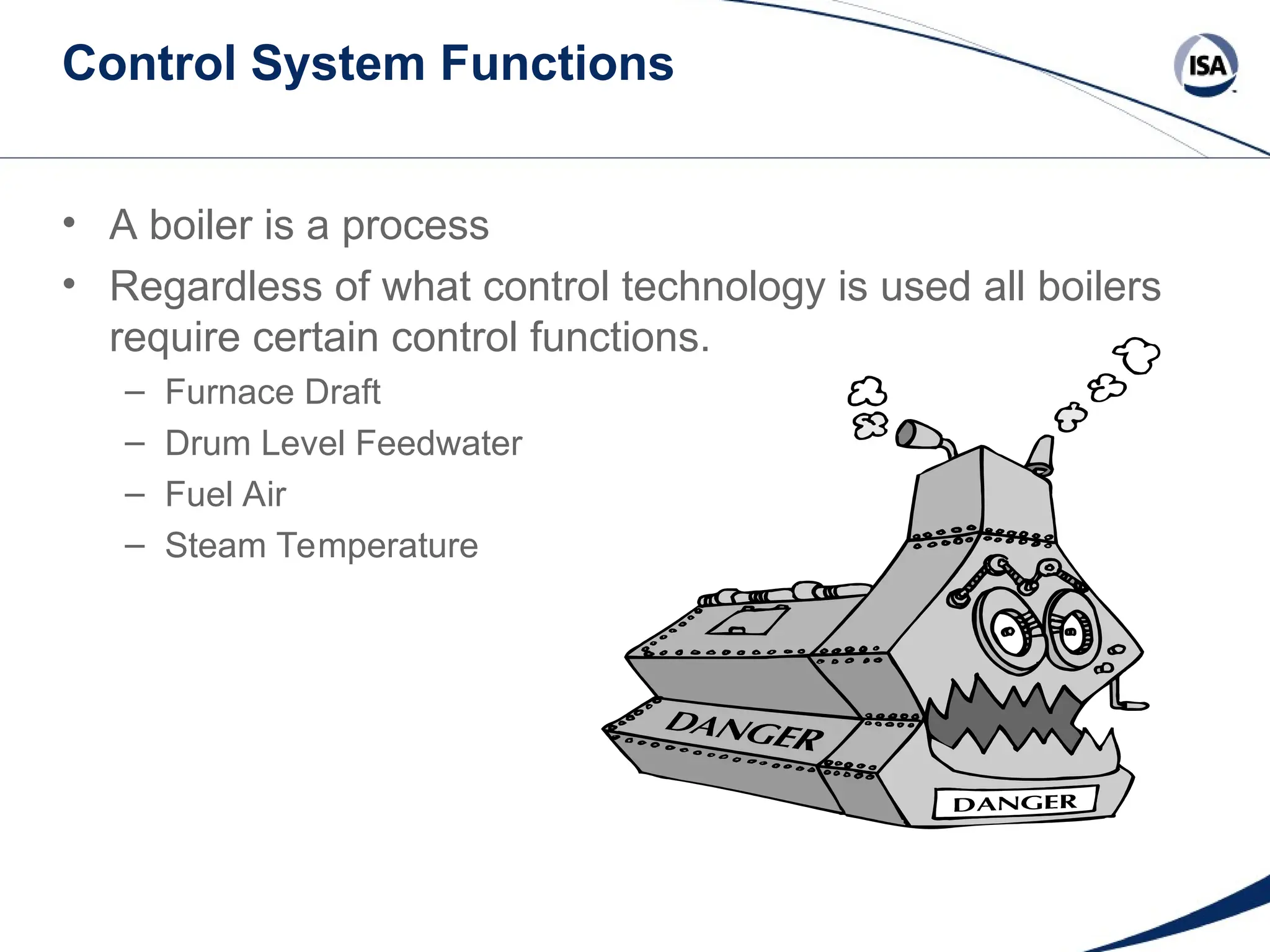
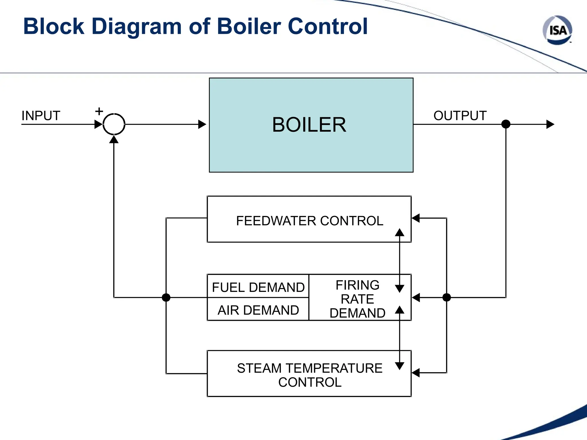
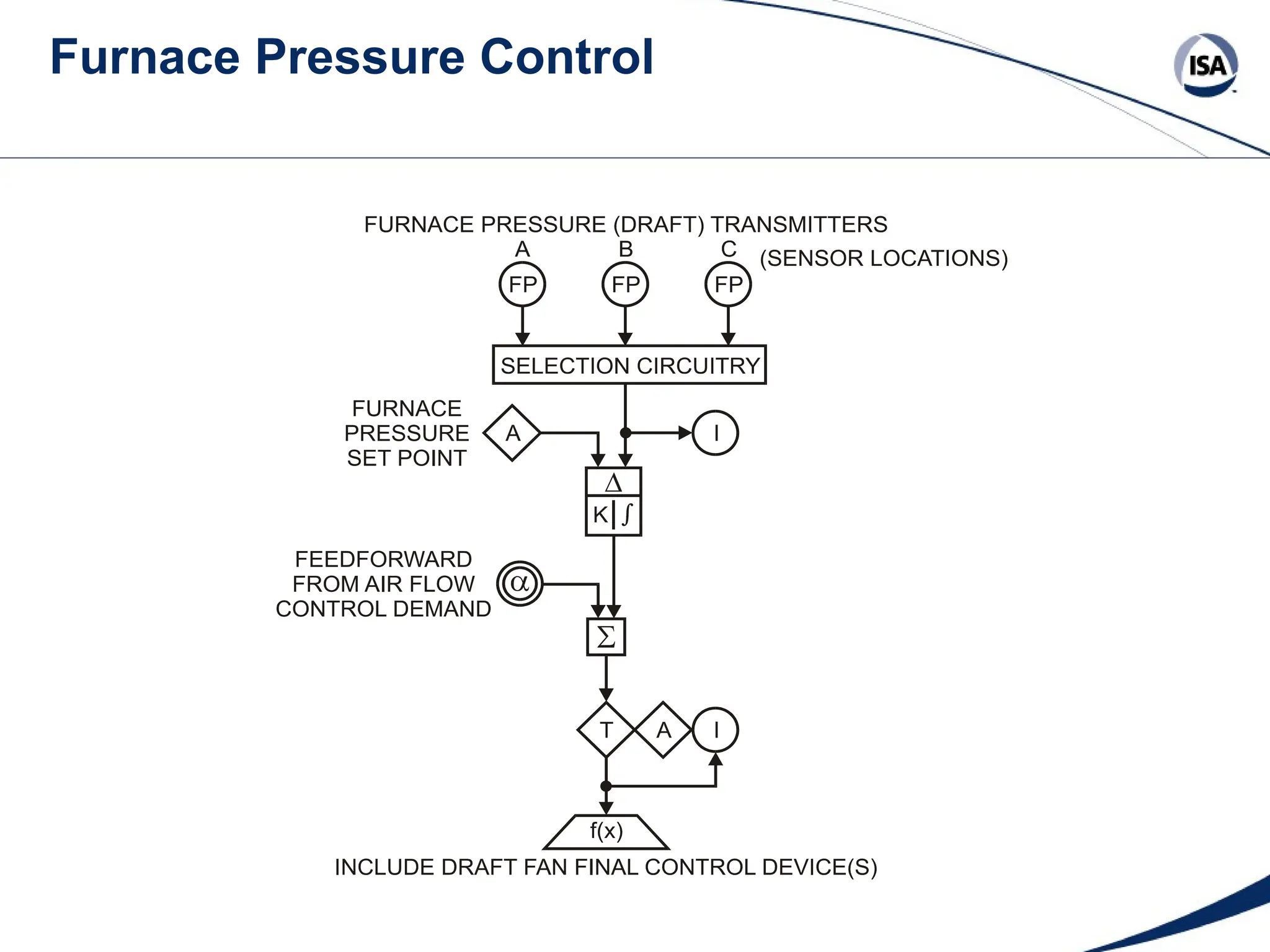
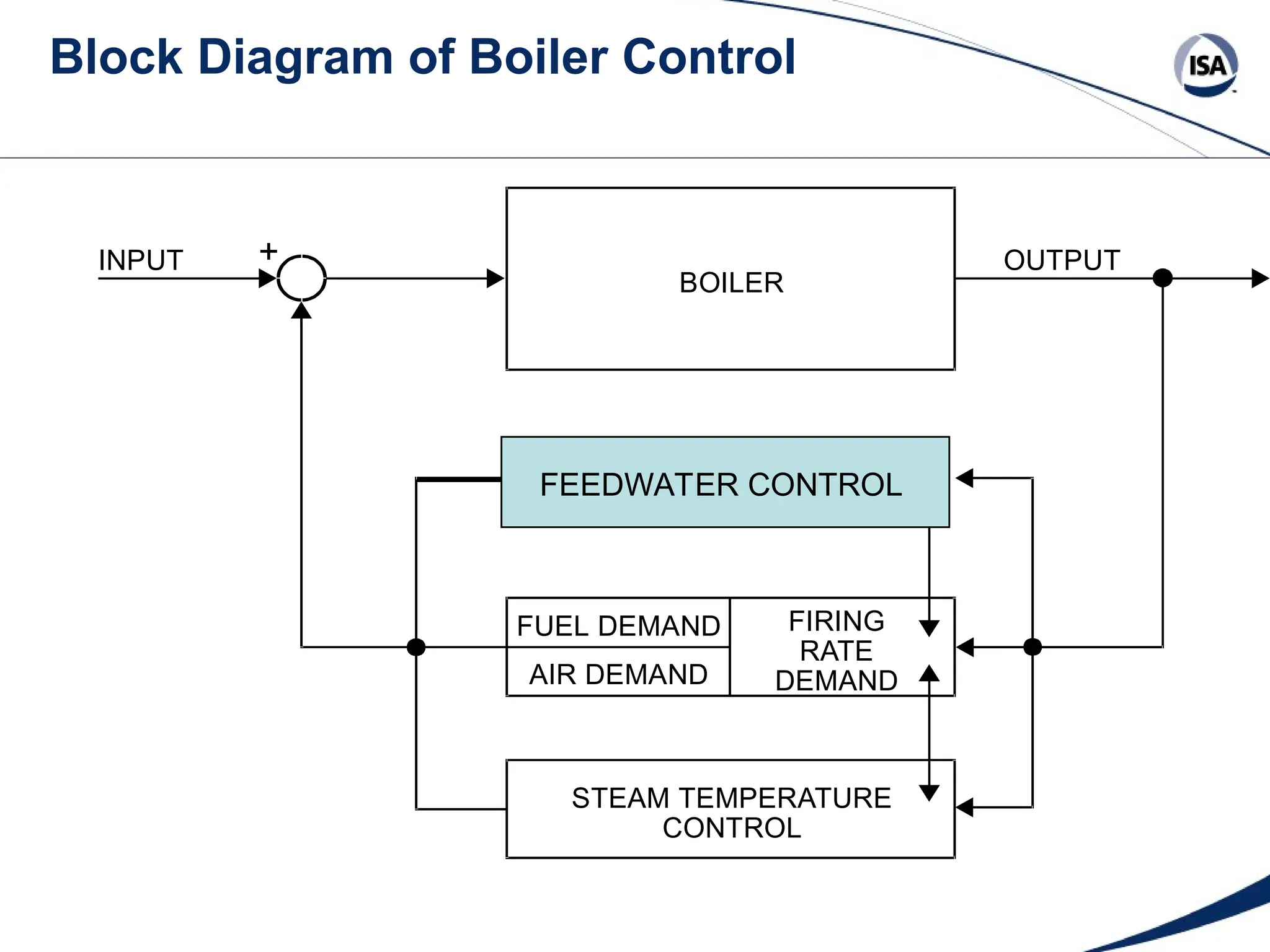
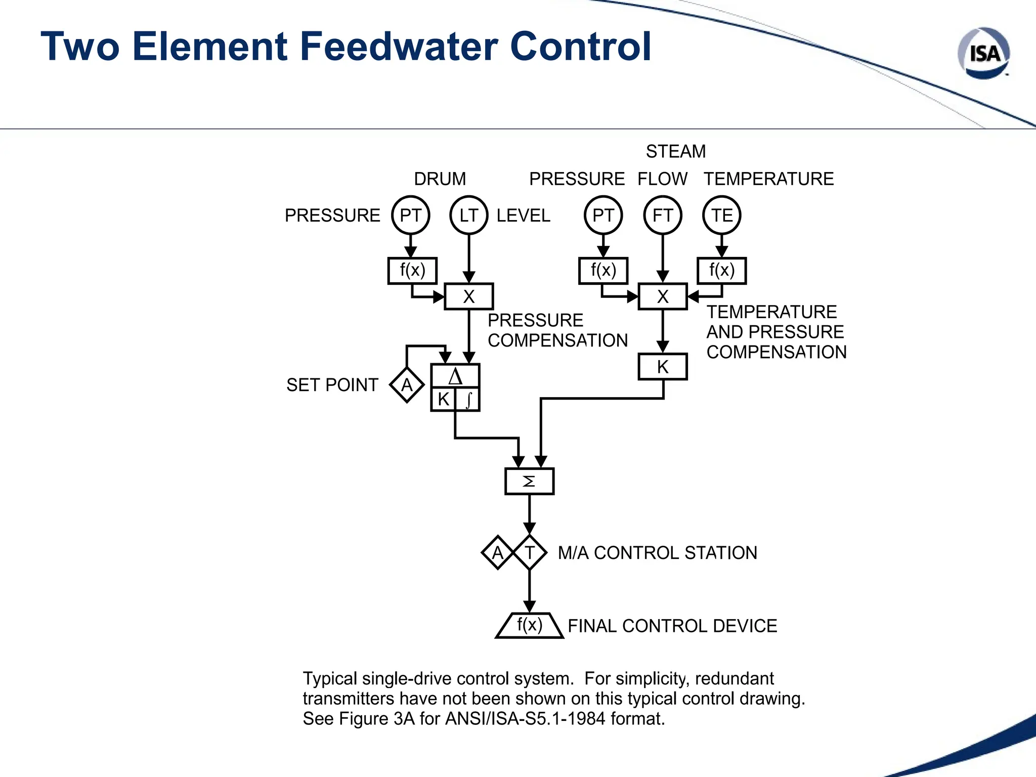
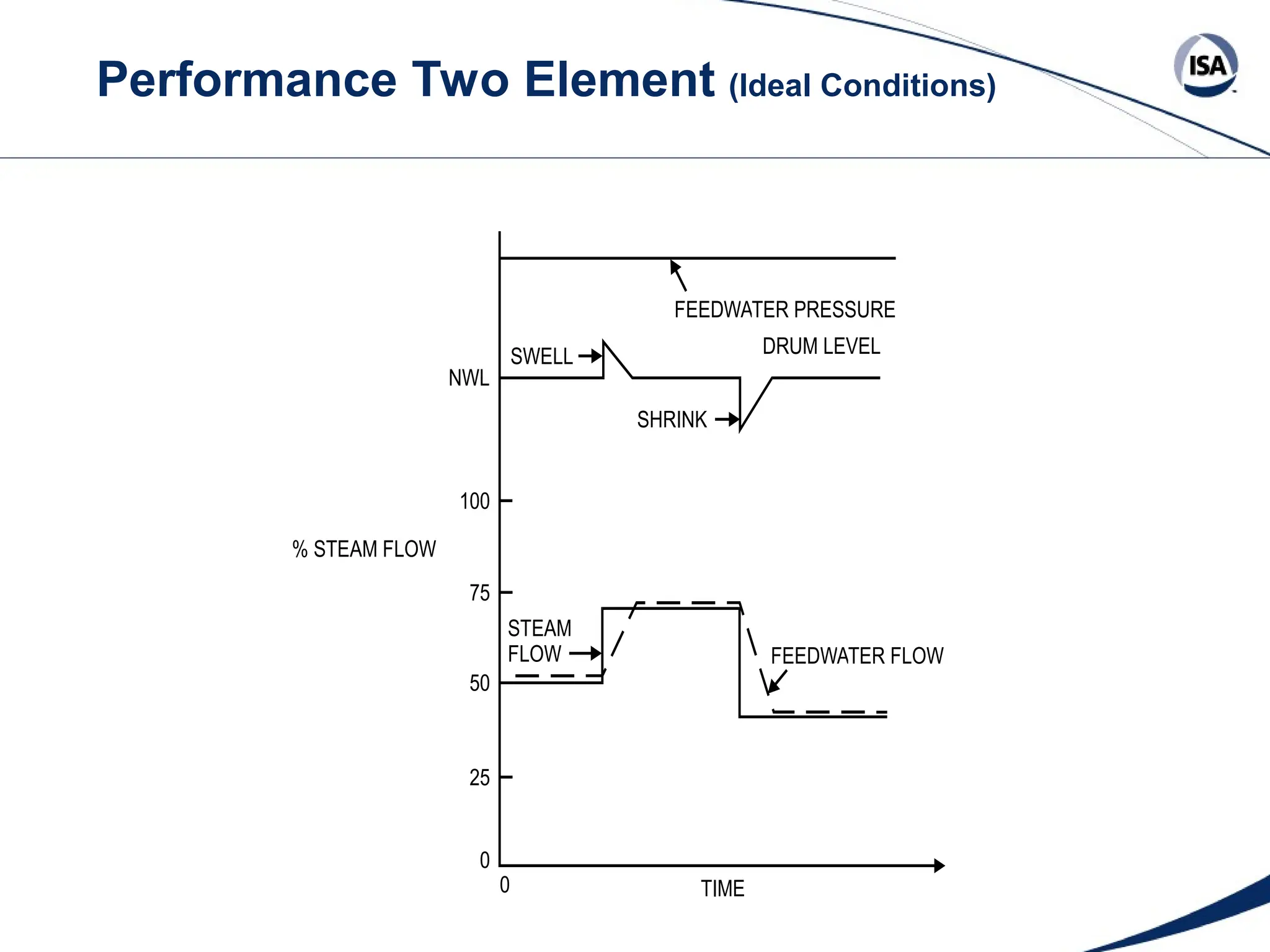
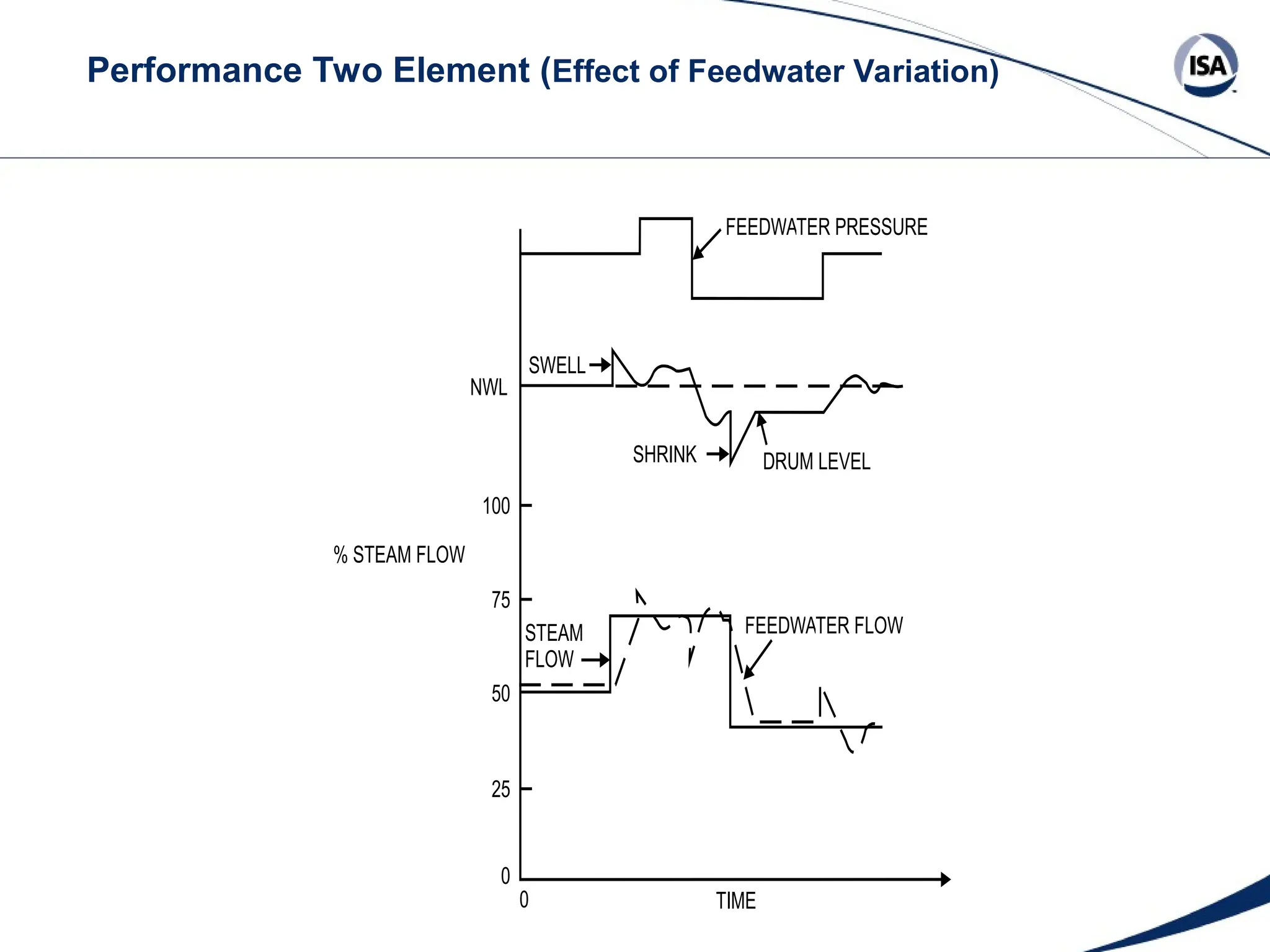
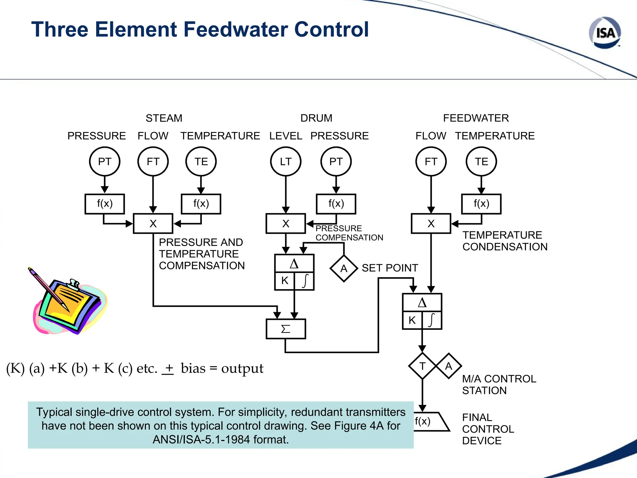
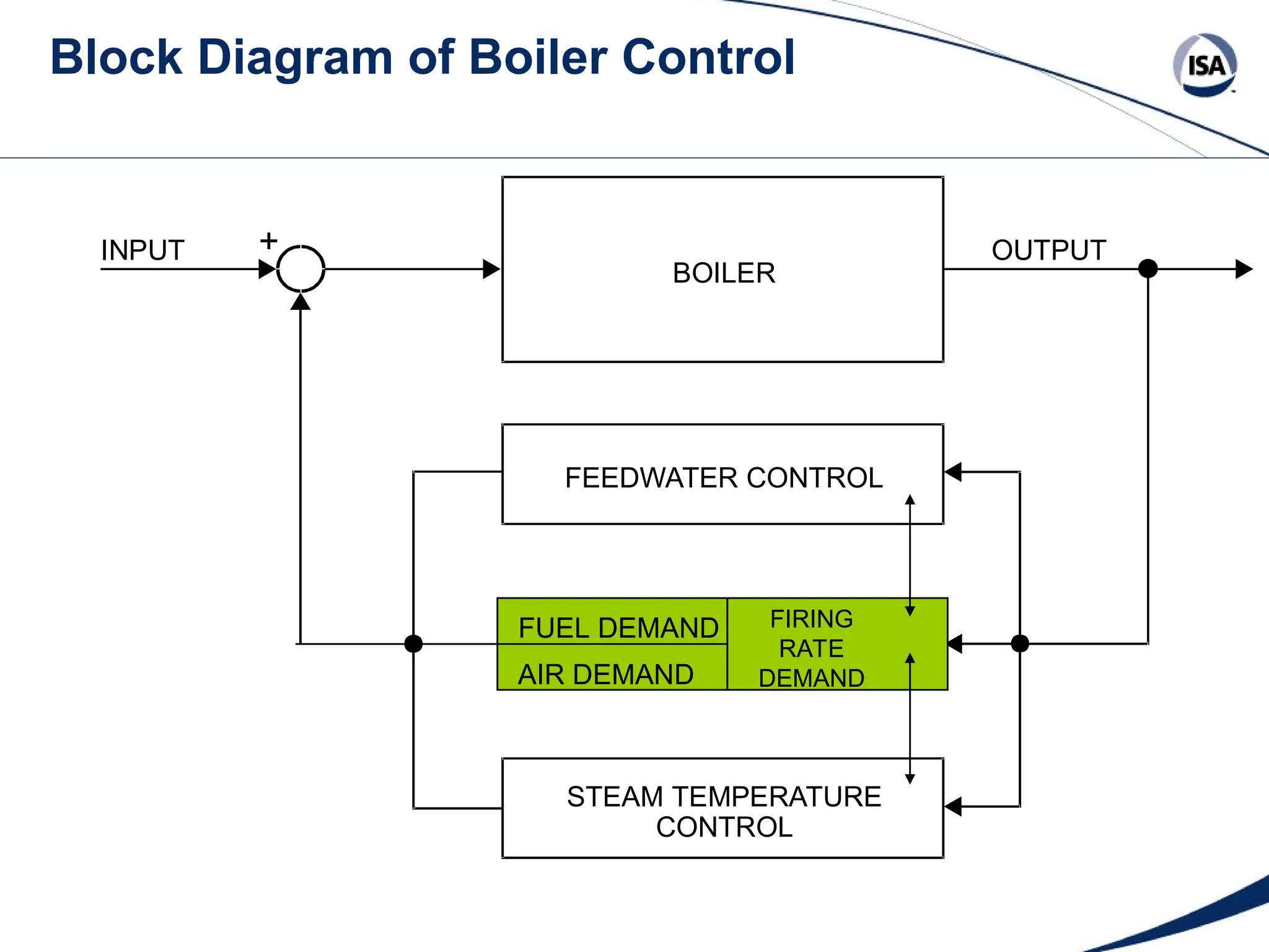
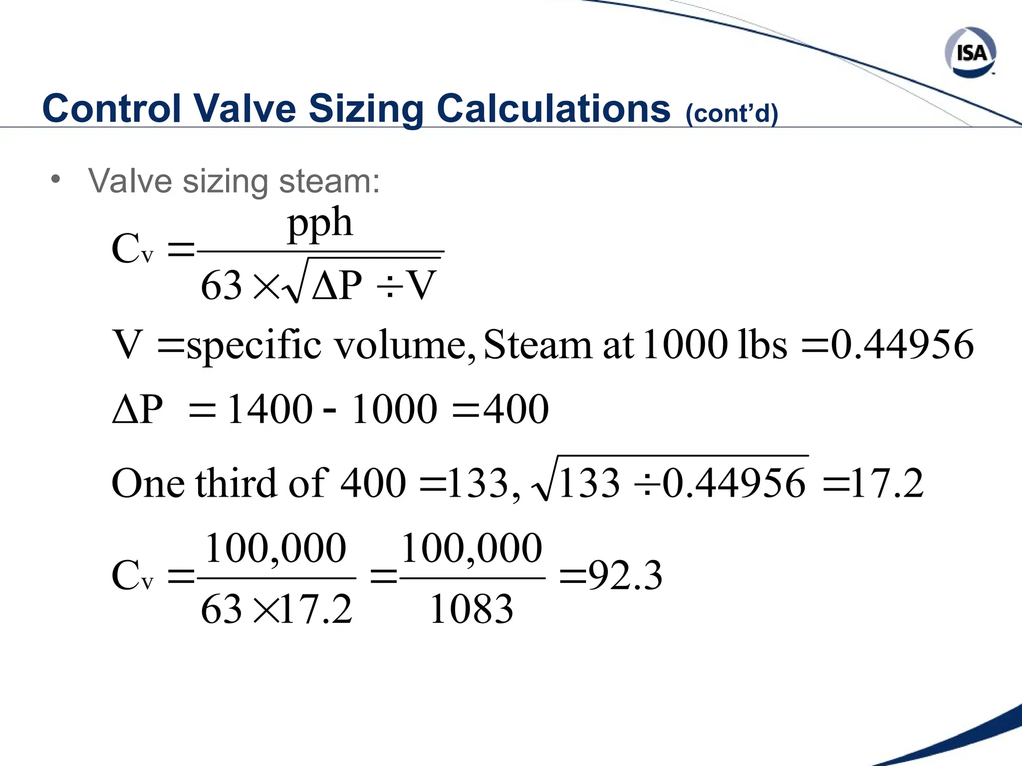
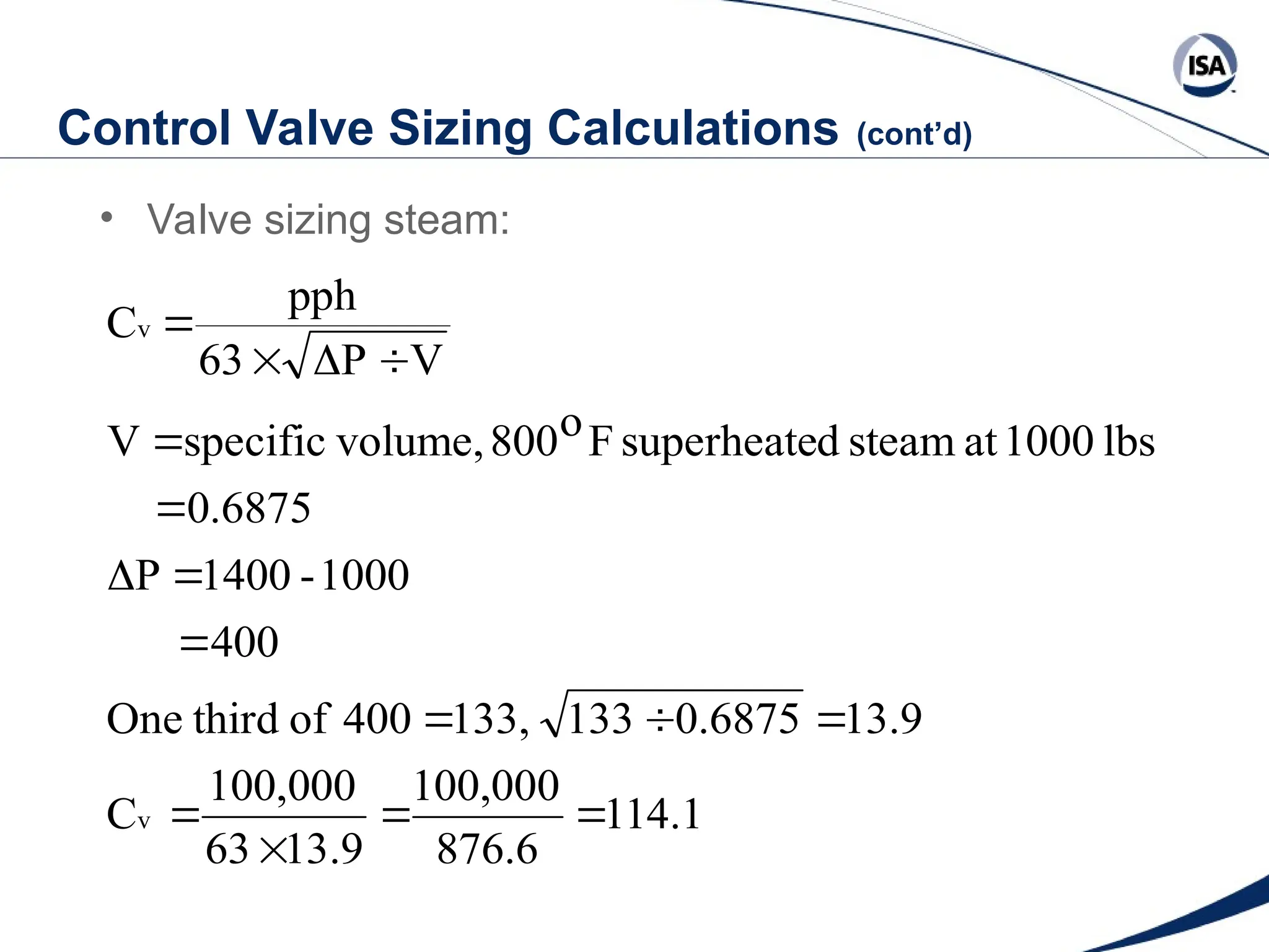
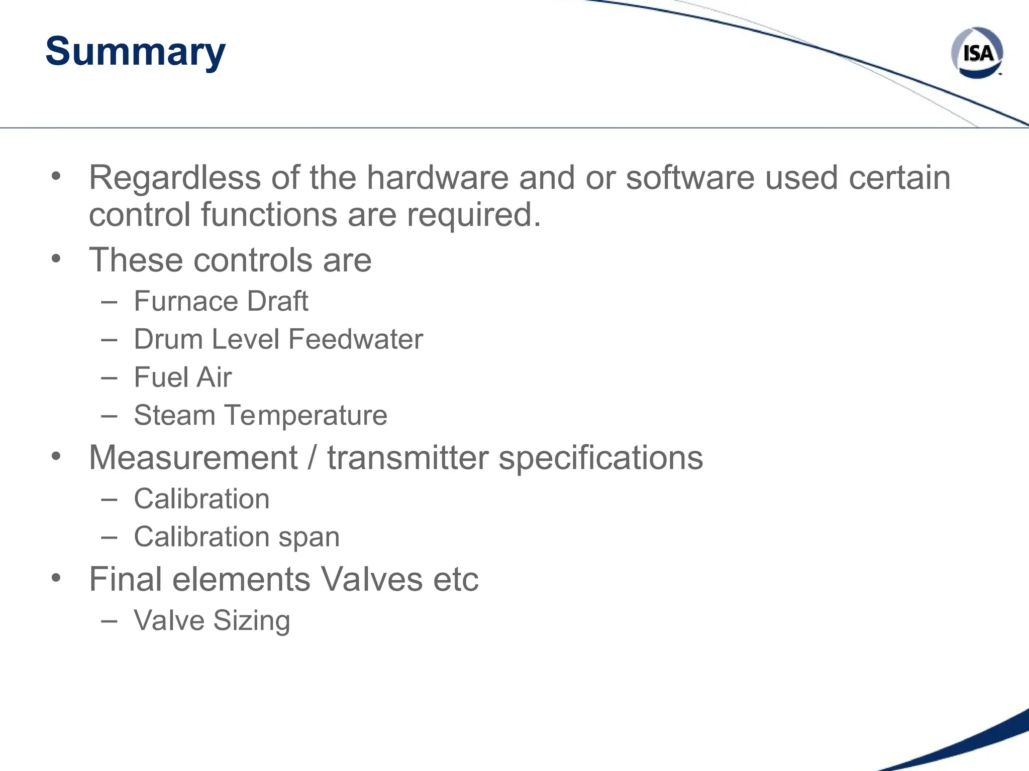
Standards
Certification
Education & Training
Publishing
Conferences & Exhibits
Automation Connections
ISA EXPO
2006
Standards
Certification
Education & Training
Publishing
Conferences & Exhibits
Boiler Control Systems
Engineering
Jerry Gilman
Control System Functions
• A boiler is a process
• Regardless of what control technology is used all boilers
require certain control functions.
– Furnace Draft
– Drum Level Feedwater
– Fuel Air
– Steam Temperature
Control System Considerations
• Draft
• Drum level feedwater
– Single element
– Two element
– Three element
• Fuel air ratio
• Final elements Valves etc
– Valve Sizing
Basic Diagram of a Boiler
WATER
FUEL
AIR
MIXING OF
FUEL & AIR
HEAT
TRANSFER
SURFACE
FURNACE
STEAM/WATER SYSTEM
STEAM
BLOWDOWN
FLUE GAS
ASH
Steam & Mud Drum / Circulation
STEAM
STEAM
MUD
DRUM
FUEL
FURNACE
FLAME
AIR
GAS BAFFLES
FLUE GAS
CIRCULATION
WATER
CIRCULATES
CLOCKWISE
SAMA Symbols
Scientific Apparatus Makers Association
ENCLOSURE SYMBOLS
Table 1
Function Symbol
Measuring or
Readout
Manual Signal
Processing
Automatic Signal
Processing
Final Controlling
Within a circle use a letter symbol from Table II
Within other enclosures us a symbol from Table III
SAMA Symbols (cont’d)
MEASURING/READOUT LETTERS
Table II
Process Variable Function
A = Analysis**
C = Conductivity
D = Density
F = Flow
L = Level
M = Moisture
P = Pressure
S = Speed
T = Temperature
V = Viscosity
W = Weight
Z = Position
R = Recording
I = Indicating
T = Transmitter
RT = Recording
Transmitter
IT = Indicating
Transmitter
FRT
FR
**Self-defining symbols such as O 2 , pH, etc., can be used in place of A.
SAMA Symbols (Table III)
SIGNAL SIGNAL
FUNCTION PROCESSING
SYMBOL
FUNCTION PROCESSING
SYMBOL
SUMMING
 or + INTEGRATE OR TOTALIZE Q
AVERAGING
/n HIGH SELECTING
DIFFERENCE
 or - LOW SELECTING
PROPORTIONAL K or P HIGH LIMITING
INTEGRAL
or I LOW LIMITING
DERIVATIVE d/dt or D REVERSE PROPORTIONAL -K or -P
MULTIPLYING X VELOCITY LIMITING V
DIVIDING
 BIAS

ROOT EXTRACTION
 TIME FUNCTION f(t)
EXPONENTIAL X
n VARIABLE SIGNAL
GENERATION
A
NON-LINEAR FUNCTION f(x) TRANSFER T
TRI-STATE SIGNAL
(RAISE, HOLD, LOWER)
 SIGNAL MONITOR H/, H/L, /L
SAMA Legend
T A
A
K ∫
1. CONTROLLER
SET POINT
GENERATOR
PROPORTIONAL
RESET
MANUAL SIGNAL
GENERATOR
AUTO./MAN.
TRANSFER SWITCH
T A
A
2. AUTO MANUAL + BIAS STATION
BIAS
ADJUSTMENT
MANUAL SIGNAL
GENERATOR
AUTO./MAN.
TRANSFER SWITCH
±
Measuring or Readout
Automatic Signal Processing
Manual Signal Processing
Final Controlling
Signal Repeater
∑ Summing ∑/h Summing
d/d1 Derivative ∆ Difference ∫ Integral
K, -K Proportional, Reverse Proportional
X Multiplying ÷ Dividing √ Root Extracting
f(x) Non Linear or Unspecified Function
f(t) Time Function
> High Selecting < Low Selecting
High Limiting Low Limiting
Velocity or Rate Limiter
+, -, ± Bias
>
|
>
|
|
Simple Feedback Control
PRIMARY VARIABLE
XT
K
A T A
f(x)
SET POINT
PROCESS
MANIPULATED VARIABLE
Feedforward Plus Feedback Control
PRIMARY VARIABLE
XT
YT
SECONDARY
VARIABLE
A T A
f(x)
MANIPULATED VARIABLE
PROCESS
SET POINT
K
Cascade Control
PRIMARY VARIABLE
XT
ZT
K
K
SET POINT
A A
T
PROCESS
f(x)
MANIPULATED VARIABLE
SECONDARY
VARIABLE
Ratio Control
A T A
f(x)
MANIPULATED VARIABLE
K
RATIO SET
X
YT
UNCONTROLLED VARIABLE
CONTROLLED
VARIABLE
XT
PROCESS
Block Diagram of Boiler Control
+
INPUT OUTPUT
FIRING
RATE
DEMAND
FUEL DEMAND
AIR DEMAND
FEEDWATER CONTROL
STEAM TEMPERATURE
CONTROL
BOILER
Furnace Pressure Control
Block Diagram of Boiler Control
+
INPUT
BOILER
OUTPUT
FIRING
RATE
DEMAND
FUEL DEMAND
AIR DEMAND
STEAM TEMPERATURE
CONTROL
FEEDWATER CONTROL
Boiler Steam Drum Swell / Shrink
STEAM
STEAM
SATURATED
WATER
WATER
FEEDWATER
WATER-MIXED STEAM BUBBLES
Single Element Feedwater Control
SET POINT
K
T
f(x)
A
A
X
LT PT
f(x)
FINAL CONTROL DEVICE
M/A CONTROL STATION
PRESSURE
COMPENSATION
DRUM PRESSURE
DRUM LEVEL


Typical single-drive control system. For simplicity, redun-
dant transmitters have not been shown on this typical
control drawing. See Figure 2A for ANSI/ISA-S5.1-1984
format.
Single Element Control Action
* INTERACTION WITH FIRING RATE CONTROL DUE TO IMBALANCE
BETWEEN STEAM FLOW AND FEEDWATER FLOW.
% STEAM FLOW
FEEDWATER FLOW
STEAM
FLOW
*
*
TIME
0
0
25
50
75
100
NWL
SHRINK
DRUM LEVEL
SWELL
Two Element Feedwater Control


f(x)
K
T
A
A
X X
K
LT
PT PT FT TE
f(x) f(x) f(x)
FINAL CONTROL DEVICE
M/A CONTROL STATION
SET POINT
PRESSURE
COMPENSATION
TEMPERATURE
AND PRESSURE
COMPENSATION
LEVEL
PRESSURE
STEAM
TEMPERATURE
FLOW
DRUM
PRESSURE
Typical single-drive control system. For simplicity, redundant
transmitters have not been shown on this typical control drawing.
See Figure 3A for ANSI/ISA-S5.1-1984 format.
Performance Two Element (Ideal Conditions)
NWL
100
75
50
25
0
0 TIME
STEAM
FLOW FEEDWATER FLOW
% STEAM FLOW
SWELL
SHRINK
DRUM LEVEL
FEEDWATER PRESSURE
Performance Two Element (Effect of Feedwater Variation)
NWL
SWELL
SHRINK DRUM LEVEL
100
75
50
STEAM
FLOW
25
0
0 TIME
FEEDWATER FLOW
% STEAM FLOW
FEEDWATER PRESSURE
Three Element Feedwater Control
PRESSURE
COMPENSATION
f(x)
A
X
PT FT TE
f(x) f(x)
X
LT PT
f(x)
X
FT TE
f(x)
K
K


T A
FINAL
CONTROL
DEVICE
M/A CONTROL
STATION
SET POINT
PRESSURE AND
TEMPERATURE
COMPENSATION
STEAM
TEMPERATURE
FLOW
PRESSURE
Typical single-drive control system. For simplicity, redundant
transmitters have not been shown on this typical control drawing.
See Figure 4A for ANSI/ISA-S5.1-1984 format.
LEVEL PRESSURE
DRUM
TEMPERATURE
CONDENSATION
FLOW TEMPERATURE
FEEDWATER
Typical single-drive control system. For simplicity, redundant transmitters
have not been shown on this typical control drawing. See Figure 4A for
ANSI/ISA-5.1-1984 format.
(K) (a) +K (b) + K (c) etc. + bias = output
Performance Three Element
Block Diagram of Boiler Control
+
INPUT
BOILER
OUTPUT
FEEDWATER CONTROL
STEAM TEMPERATURE
CONTROL
FUEL DEMAND
AIR DEMAND
FIRING
RATE
DEMAND
Firing Single Fuel/Cross Limiting
AIR CONTROL
FT PT FT
A
A T
P I
A T
P I
A T
P I
f(x)
f(x)
Fuel FLOW
STEAM
HEADER PRESSURE AIR FLOW
SP SP
LO SELECT HI SELECT
Fuel CONTROL
Fuel Feed
AIR DAMPER
Cross Limit Control With O2 Trim
GAS FLOW
STEAM
FLOW
AIR CONTROL
GAS CONTROL
HI SELECT
LO SELECT
SP SP
STEAM
HEADER PRESSURE AIR FLOW O2
AIR DAMPER
GAS VALVE
FT PT FT AT
P
P P
T
T
A
A
A A
I
I I
P
T
A
I
f(x)
f(x)
Flow Characteristics
100
50
% FUEL AND
AIR FLOW
0
0 50 100
% CONTROL RANGE
A,B – BASIC FLOW CHARACTERISTICS OF CONTROLLED DEVICES
C,D – CHARACTERISTICS AFTER LINEARIZATION AND ALIGNMENT
AIR
FUEL
FUEL
AIR
(B)
(A)
(D)
(C)
Non Linear Flow
10 20 30 40 50 60 70 80 90 100
1 4 9 16 25 36 49 64 81 100
Flow in %
0
10
20
30
40
50
60
70
80
90
100
0 1
4
9
16
25
36
49
64
81
100
0
20
40
60
80
100
120
1 2 3 4 5 6 7 8 9 10 11
Series1
Series2
Non Linear Flow
0 10 20 30 40 50 60 70 80 90 100
0 1 4 9 16 25 36 49 64 81 100
Flow in %
0
10
20
30
40
50
60
70
80
90
100
0 1
4
9
16
25
36
49
64
81
100
0
20
40
60
80
100
120
1 2 3 4 5 6 7 8 9 10 11
Series1
Series2
Characterization
0 10 20 30 40 50 60 70 80 OUT
0 7.5 15 22.5 30 37.5 45 52.5 60 IN
0
10
20
30
40
50
60
70
80
0
7.5
15
22.5
30
37.5
45
52.5
60
0
10
20
30
40
50
60
70
80
90
1 2 3 4 5 6 7 8 9
Serie
Serie
Control Valve Sizing Calculations
• Cv = Number of US gallons of water at 60o
F that
flows through a valve in one minute when the
pressure differential across the valve is one pound
per square inch
– Valve sizing water no density consideration:
– The term Cv is generally used in industry for calculating the
relative flow capacity in valves
valve
rop across
pressure d
ΔP
ravity
specific g
SG
gpm
Q



Control Valve Sizing Calculations (cont’d)
• Valve sizing water no density consideration:
P = pressure drop across valve typical third of drop
600,000 pph water = 600,000  8.34 lb/gal = 1200 gpm
P = pressure drop across valve, typical a third of drop
Pump pressure = 2000 psi,
Drum pressure = 1400 psi
2000  1400 = 600
600  1/3 = 200 valve drop
ΔP
SG
GPM
Cv 

Control Valve Sizing Calculations (cont’d)
• The calculation 600,000 pph is:
• The calculation for 250,000 pph is:
84.85
200
1.0
1200
C
P
G
S
GPM
C
v
v






24.49
150
1.0
300
Cv 


Control Valve Sizing Calculations (cont’d)
• Valve sizing water 450o
F, SG = 0.827
• The calculation 600,000 pph is:
Cv at 60o
= 84.85
Cv at 450o
= 77.16
77.16
200
0.827
1200
C
P
G
S
GPM
C
v
v






Control Valve Sizing Calculations (cont’d)
• Valve sizing steam:
92.3
1083
100,000
17.2
63
100,000
C
17.2
0.44956
133
133,
400
of
third
One
400
1000
1400
ΔP
0.44956
lbs
1000
at
Steam
volume,
specific
V
V
P
63
pph
C
v
v
















Control Valve Sizing Calculations (cont’d)
• Valve sizing steam:
114.1
876.6
100,000
13.9
63
100,000
C
13.9
0.6875
133
133,
400
of
third
One
400
1000
-
1400
P
0.6875
lbs
1000
at
steam
d
superheate
F
o
800
volume,
specific
V
V
P
63
pph
C
v
v
















Summary
• Regardless of the hardware and or software used certain
control functions are required.
• These controls are
– Furnace Draft
– Drum Level Feedwater
– Fuel Air
– Steam Temperature
• Measurement / transmitter specifications
– Calibration
– Calibration span
• Final elements Valves etc
– Valve Sizing
Questions and Discussion
Related Resources from ISA
Phone: (919) 549-8411
E-mail Address: info@isa.org
• Boiler Control Systems Engineering Jerry Gilman
• The Control of Boilers Sam G. Dukelow
• ISA Courses
• ES15 Boiler Control System Engineering
– Three day course
– One day overview
– WEB introduction course
• ES16 Burner Management System Engineering
– Three day course
– One day overview

BoilerControl Engineering Basics ISA Expo.ppt

  • 1.
    Standards Certification Education & Training Publishing Conferences& Exhibits Automation Connections ISA EXPO 2006
  • 2.
    Standards Certification Education & Training Publishing Conferences& Exhibits Boiler Control Systems Engineering Jerry Gilman
  • 3.
    Control System Functions •A boiler is a process • Regardless of what control technology is used all boilers require certain control functions. – Furnace Draft – Drum Level Feedwater – Fuel Air – Steam Temperature
  • 4.
    Control System Considerations •Draft • Drum level feedwater – Single element – Two element – Three element • Fuel air ratio • Final elements Valves etc – Valve Sizing
  • 5.
    Basic Diagram ofa Boiler WATER FUEL AIR MIXING OF FUEL & AIR HEAT TRANSFER SURFACE FURNACE STEAM/WATER SYSTEM STEAM BLOWDOWN FLUE GAS ASH
  • 6.
    Steam & MudDrum / Circulation STEAM STEAM MUD DRUM FUEL FURNACE FLAME AIR GAS BAFFLES FLUE GAS CIRCULATION WATER CIRCULATES CLOCKWISE
  • 7.
    SAMA Symbols Scientific ApparatusMakers Association ENCLOSURE SYMBOLS Table 1 Function Symbol Measuring or Readout Manual Signal Processing Automatic Signal Processing Final Controlling Within a circle use a letter symbol from Table II Within other enclosures us a symbol from Table III
  • 8.
    SAMA Symbols (cont’d) MEASURING/READOUTLETTERS Table II Process Variable Function A = Analysis** C = Conductivity D = Density F = Flow L = Level M = Moisture P = Pressure S = Speed T = Temperature V = Viscosity W = Weight Z = Position R = Recording I = Indicating T = Transmitter RT = Recording Transmitter IT = Indicating Transmitter FRT FR **Self-defining symbols such as O 2 , pH, etc., can be used in place of A.
  • 9.
    SAMA Symbols (TableIII) SIGNAL SIGNAL FUNCTION PROCESSING SYMBOL FUNCTION PROCESSING SYMBOL SUMMING  or + INTEGRATE OR TOTALIZE Q AVERAGING /n HIGH SELECTING DIFFERENCE  or - LOW SELECTING PROPORTIONAL K or P HIGH LIMITING INTEGRAL or I LOW LIMITING DERIVATIVE d/dt or D REVERSE PROPORTIONAL -K or -P MULTIPLYING X VELOCITY LIMITING V DIVIDING  BIAS  ROOT EXTRACTION  TIME FUNCTION f(t) EXPONENTIAL X n VARIABLE SIGNAL GENERATION A NON-LINEAR FUNCTION f(x) TRANSFER T TRI-STATE SIGNAL (RAISE, HOLD, LOWER)  SIGNAL MONITOR H/, H/L, /L
  • 10.
    SAMA Legend T A A K∫ 1. CONTROLLER SET POINT GENERATOR PROPORTIONAL RESET MANUAL SIGNAL GENERATOR AUTO./MAN. TRANSFER SWITCH T A A 2. AUTO MANUAL + BIAS STATION BIAS ADJUSTMENT MANUAL SIGNAL GENERATOR AUTO./MAN. TRANSFER SWITCH ± Measuring or Readout Automatic Signal Processing Manual Signal Processing Final Controlling Signal Repeater ∑ Summing ∑/h Summing d/d1 Derivative ∆ Difference ∫ Integral K, -K Proportional, Reverse Proportional X Multiplying ÷ Dividing √ Root Extracting f(x) Non Linear or Unspecified Function f(t) Time Function > High Selecting < Low Selecting High Limiting Low Limiting Velocity or Rate Limiter +, -, ± Bias > | > | |
  • 11.
    Simple Feedback Control PRIMARYVARIABLE XT K A T A f(x) SET POINT PROCESS MANIPULATED VARIABLE
  • 12.
    Feedforward Plus FeedbackControl PRIMARY VARIABLE XT YT SECONDARY VARIABLE A T A f(x) MANIPULATED VARIABLE PROCESS SET POINT K
  • 13.
    Cascade Control PRIMARY VARIABLE XT ZT K K SETPOINT A A T PROCESS f(x) MANIPULATED VARIABLE SECONDARY VARIABLE
  • 14.
    Ratio Control A TA f(x) MANIPULATED VARIABLE K RATIO SET X YT UNCONTROLLED VARIABLE CONTROLLED VARIABLE XT PROCESS
  • 15.
    Block Diagram ofBoiler Control + INPUT OUTPUT FIRING RATE DEMAND FUEL DEMAND AIR DEMAND FEEDWATER CONTROL STEAM TEMPERATURE CONTROL BOILER
  • 16.
  • 17.
    Block Diagram ofBoiler Control + INPUT BOILER OUTPUT FIRING RATE DEMAND FUEL DEMAND AIR DEMAND STEAM TEMPERATURE CONTROL FEEDWATER CONTROL
  • 18.
    Boiler Steam DrumSwell / Shrink STEAM STEAM SATURATED WATER WATER FEEDWATER WATER-MIXED STEAM BUBBLES
  • 19.
    Single Element FeedwaterControl SET POINT K T f(x) A A X LT PT f(x) FINAL CONTROL DEVICE M/A CONTROL STATION PRESSURE COMPENSATION DRUM PRESSURE DRUM LEVEL   Typical single-drive control system. For simplicity, redun- dant transmitters have not been shown on this typical control drawing. See Figure 2A for ANSI/ISA-S5.1-1984 format.
  • 20.
    Single Element ControlAction * INTERACTION WITH FIRING RATE CONTROL DUE TO IMBALANCE BETWEEN STEAM FLOW AND FEEDWATER FLOW. % STEAM FLOW FEEDWATER FLOW STEAM FLOW * * TIME 0 0 25 50 75 100 NWL SHRINK DRUM LEVEL SWELL
  • 21.
    Two Element FeedwaterControl   f(x) K T A A X X K LT PT PT FT TE f(x) f(x) f(x) FINAL CONTROL DEVICE M/A CONTROL STATION SET POINT PRESSURE COMPENSATION TEMPERATURE AND PRESSURE COMPENSATION LEVEL PRESSURE STEAM TEMPERATURE FLOW DRUM PRESSURE Typical single-drive control system. For simplicity, redundant transmitters have not been shown on this typical control drawing. See Figure 3A for ANSI/ISA-S5.1-1984 format.
  • 22.
    Performance Two Element(Ideal Conditions) NWL 100 75 50 25 0 0 TIME STEAM FLOW FEEDWATER FLOW % STEAM FLOW SWELL SHRINK DRUM LEVEL FEEDWATER PRESSURE
  • 23.
    Performance Two Element(Effect of Feedwater Variation) NWL SWELL SHRINK DRUM LEVEL 100 75 50 STEAM FLOW 25 0 0 TIME FEEDWATER FLOW % STEAM FLOW FEEDWATER PRESSURE
  • 24.
    Three Element FeedwaterControl PRESSURE COMPENSATION f(x) A X PT FT TE f(x) f(x) X LT PT f(x) X FT TE f(x) K K   T A FINAL CONTROL DEVICE M/A CONTROL STATION SET POINT PRESSURE AND TEMPERATURE COMPENSATION STEAM TEMPERATURE FLOW PRESSURE Typical single-drive control system. For simplicity, redundant transmitters have not been shown on this typical control drawing. See Figure 4A for ANSI/ISA-S5.1-1984 format. LEVEL PRESSURE DRUM TEMPERATURE CONDENSATION FLOW TEMPERATURE FEEDWATER Typical single-drive control system. For simplicity, redundant transmitters have not been shown on this typical control drawing. See Figure 4A for ANSI/ISA-5.1-1984 format. (K) (a) +K (b) + K (c) etc. + bias = output
  • 25.
  • 26.
    Block Diagram ofBoiler Control + INPUT BOILER OUTPUT FEEDWATER CONTROL STEAM TEMPERATURE CONTROL FUEL DEMAND AIR DEMAND FIRING RATE DEMAND
  • 27.
    Firing Single Fuel/CrossLimiting AIR CONTROL FT PT FT A A T P I A T P I A T P I f(x) f(x) Fuel FLOW STEAM HEADER PRESSURE AIR FLOW SP SP LO SELECT HI SELECT Fuel CONTROL Fuel Feed AIR DAMPER
  • 28.
    Cross Limit ControlWith O2 Trim GAS FLOW STEAM FLOW AIR CONTROL GAS CONTROL HI SELECT LO SELECT SP SP STEAM HEADER PRESSURE AIR FLOW O2 AIR DAMPER GAS VALVE FT PT FT AT P P P T T A A A A I I I P T A I f(x) f(x)
  • 29.
    Flow Characteristics 100 50 % FUELAND AIR FLOW 0 0 50 100 % CONTROL RANGE A,B – BASIC FLOW CHARACTERISTICS OF CONTROLLED DEVICES C,D – CHARACTERISTICS AFTER LINEARIZATION AND ALIGNMENT AIR FUEL FUEL AIR (B) (A) (D) (C)
  • 30.
    Non Linear Flow 1020 30 40 50 60 70 80 90 100 1 4 9 16 25 36 49 64 81 100 Flow in % 0 10 20 30 40 50 60 70 80 90 100 0 1 4 9 16 25 36 49 64 81 100 0 20 40 60 80 100 120 1 2 3 4 5 6 7 8 9 10 11 Series1 Series2
  • 31.
    Non Linear Flow 010 20 30 40 50 60 70 80 90 100 0 1 4 9 16 25 36 49 64 81 100 Flow in % 0 10 20 30 40 50 60 70 80 90 100 0 1 4 9 16 25 36 49 64 81 100 0 20 40 60 80 100 120 1 2 3 4 5 6 7 8 9 10 11 Series1 Series2
  • 32.
    Characterization 0 10 2030 40 50 60 70 80 OUT 0 7.5 15 22.5 30 37.5 45 52.5 60 IN 0 10 20 30 40 50 60 70 80 0 7.5 15 22.5 30 37.5 45 52.5 60 0 10 20 30 40 50 60 70 80 90 1 2 3 4 5 6 7 8 9 Serie Serie
  • 33.
    Control Valve SizingCalculations • Cv = Number of US gallons of water at 60o F that flows through a valve in one minute when the pressure differential across the valve is one pound per square inch – Valve sizing water no density consideration: – The term Cv is generally used in industry for calculating the relative flow capacity in valves valve rop across pressure d ΔP ravity specific g SG gpm Q   
  • 34.
    Control Valve SizingCalculations (cont’d) • Valve sizing water no density consideration: P = pressure drop across valve typical third of drop 600,000 pph water = 600,000  8.34 lb/gal = 1200 gpm P = pressure drop across valve, typical a third of drop Pump pressure = 2000 psi, Drum pressure = 1400 psi 2000  1400 = 600 600  1/3 = 200 valve drop ΔP SG GPM Cv  
  • 35.
    Control Valve SizingCalculations (cont’d) • The calculation 600,000 pph is: • The calculation for 250,000 pph is: 84.85 200 1.0 1200 C P G S GPM C v v       24.49 150 1.0 300 Cv   
  • 36.
    Control Valve SizingCalculations (cont’d) • Valve sizing water 450o F, SG = 0.827 • The calculation 600,000 pph is: Cv at 60o = 84.85 Cv at 450o = 77.16 77.16 200 0.827 1200 C P G S GPM C v v      
  • 37.
    Control Valve SizingCalculations (cont’d) • Valve sizing steam: 92.3 1083 100,000 17.2 63 100,000 C 17.2 0.44956 133 133, 400 of third One 400 1000 1400 ΔP 0.44956 lbs 1000 at Steam volume, specific V V P 63 pph C v v                
  • 38.
    Control Valve SizingCalculations (cont’d) • Valve sizing steam: 114.1 876.6 100,000 13.9 63 100,000 C 13.9 0.6875 133 133, 400 of third One 400 1000 - 1400 P 0.6875 lbs 1000 at steam d superheate F o 800 volume, specific V V P 63 pph C v v                
  • 39.
    Summary • Regardless ofthe hardware and or software used certain control functions are required. • These controls are – Furnace Draft – Drum Level Feedwater – Fuel Air – Steam Temperature • Measurement / transmitter specifications – Calibration – Calibration span • Final elements Valves etc – Valve Sizing
  • 40.
  • 41.
    Related Resources fromISA Phone: (919) 549-8411 E-mail Address: info@isa.org • Boiler Control Systems Engineering Jerry Gilman • The Control of Boilers Sam G. Dukelow • ISA Courses • ES15 Boiler Control System Engineering – Three day course – One day overview – WEB introduction course • ES16 Burner Management System Engineering – Three day course – One day overview

Editor's Notes

  • #5  This is a basic diagram of a boiler that shows that a boiler comprises two separate systems. One system is the steam-water system, which is also called the water side of the boiler. In this system water is introduced and, upon receiving heat that is transferred through a solid metal barrier, is heated, converted to steam, and leaves the system in the form of steam. The other system of a boiler is the fuel-air-flue gas system, which is also called the fire side of the boiler. This system provides the heat that is transferred to the water. The inputs to this system are fuel and the necessary air required to burn the fuel.
  • #7  Point out the symbols are very much like ISA symbols. SAMA symbols have been used for boilers for many years and has been an international standard. Circle is for measuring or reading. Diamond manual signal. Rectangle for automatic signal processing.
  • #8  Review the symbols.
  • #9  Sum = the output equals the algebraic sum of the inputs. Square root symbol = square root function. > greater than < Less than
  • #11  Simple feedback control is shown in the control diagram . With this type of loop, changes in the primary variable feed back to a control function. The control function can be proportional-plus-integral (as shown), proportion-only, proportional-plus-derivative, integral integral-only, or proportional-plus-integral-plus-derivative. In all these cases the controller includes an error detector function, which measures the error between the primary variable and the set point. The controller output is determined by a combustion or summation of the effects of the different control action capabilities that are built into the controller. These are the proportional or gain multiplication of the error magnitude, the difference between the measured amount and the set point, the integral action based on incremental time away from set point multiplied by error magnitude, and the derivative or rate of change of the measured variable. A change in the controller output changes the manipulated variable, which through action of the process changes the process output selected as the primary variable This closes the control loop.
  • #12  In feedforward-plus-feedback control a secondary variable that has a predictable relationship with the manipulated variable is connected. In this case a change in the secondary variable causes the manipulated variable to change in anticipation of a change in the primary variable. This reduces the magnitude of the primary variable change due to the more timely control action that originates from the secondary variable. The feedback portion of the loop contains the set point and can contain any of the controller functions of the basic feedback loop. The feedforward gain is adjustable and may be greater than 1.0.
  • #13  Cascade control consists essentially of two feedback control loops connected together with the output of the primary loop acting as set point for the secondary loop. Cascade control is applied to stabilize the manipulated variable so that a predictable relationship between the manipulated variable and the primary variable can be maintained. To avoid control instability due to interaction between the two feedback control loops, it is necessary that the response time constants be substantially different. Process response of the secondary control loop should be the faster of the two. A general rule is that the time constant of the primary loop process response should be a minimum of 5 to 10 times that of the secondary loop The longer time constant of the primary loop indicates a much slower response. Because of this, a normal application would be temperature control (a normally slow loop) cascading onto flow control (a normally fast loop). Other suitable candidates for cascade control are temperature cascading onto pressure control and level control cascading onto flow control.
  • #14  Ratio control consists of a feedback controller whose set point is in direct proportion to an uncontrolled variable. The proportional relationship can be set by the operator of the process, or it can be automatically adjusted by another controller. As shown, the mathematical function is a multiplier. If the ratio is set, the set point of the controlled variable changes in direct proportion to changes in the uncontrolled variable. If the multiplication is changed, the direct proportional relationship or ratio between the controlled and the uncontrolled variables is changed. A careful examination of most boiler control applications will show that the overall control system is an interconnected matrix of the four types of control application.
  • #15  The measurements of the output process variables furnish the information to the control system. P&ID and control schemes will be developed for all boiler systems. The boiler systems, boiler / furnace, feedwater, fuel air, and steam temperature control will be review and control schemes developed. This section covers boiler / furnace system. Note parts of the overall control system are coordinated into the over all boiler control system. This course will review the systems and there control. The first to be reviewed is the boiler furnace draft control. The overall system must be applied and coordinated in a manner to minimize the effect of these interactions. The interactions can be greatly affected by the control system design.
  • #16  Furnace pressure (draft) control is required on balanced draft boilers. Shall be measured with three furnace pressure transmitters, each on a separate pressure-sensing tap S77.41 and NFPA 8502. Either the forced draft fan(s) or the induced draft fan(s) could be used to control the furnace pressure, typically the induced draft fan(s) is used. This figure utilizes a feedforward signal characterized to represent the position of the forced draft control device(s). In a properly designed and calibrated system, the output of the furnace pressure controller will remain near its midrange for all air flows. The furnace pressure control shall regulate flue gas flow to maintain furnace pressure at the desired set point in compliance with the requirements of NFPA 85G (now 8502) The furnace pressure control shall utilize a feedforward demand signal from the air flow control
  • #17  The measurements of the output process variables furnish the information to the control system. P&ID and control schemes will be developed for feedwater control. Note parts of the overall control system are coordinated into the over all boiler control system. This course will review the systems and there control. The mass of the water-steam energy carrier must be regulated. The feedwater control regulates the mass of water in the boiler. The effects of the input control actions interact, since firing rate also affects steam temperature and feedwater flow affects the steam pressure, which is the final arbiter of firing rate demand. The overall system must be applied and coordinated in a manner to minimize the effect of these interactions. The interactions can be greatly affected by the control system design.
  • #18  Feedwater comes in below water line. Water level must stay above water tubes. Over view of boiler drum
  • #19  SAMA symbol format. Single-element feedwater control. Single-element control is the minimum feedwater control system and shall be used for the following applications: 1) During start-up or at low-load operation, when flow measurements are generally not accurate. 2) When steam flow rate of change is nominal and feedwater supply pressure is essentially constant. Pressure compensation If the instruments used to measure drum level are sensitive to density variations, then density compensation technologies shall be employed.
  • #20  By adding a control system instead of a mechanical system which is proportional only better control is achieved. Mechanical systems a re proportional only control. By adding integral / reset control effect the level will come back to set point. The swell or shrink results in an increase in level on steam increase. Integral control must be tuned to be slow so the initial rise effect is reduced.
  • #21  SAMA symbol format. Two element control steam flow is added. Two-element control is the minimum feedwater control for a variable steam flow application. It is not recommended for new applications.
  • #22  This performance is recognized as having the desired pattern of flow and level relationships, and such performance meets the boiler feedwater control objectives that have been stated previously, except that of compensating for feedwater pressure variation. Tuning such a system for proper action during the shrink and swell period requires the correct balance between the effects of steam flow and drum level. The desired condition is for water flow to hold its flow rate during a load change and change only as the drum level begins to return to its set point. In this manner water inventory is smoothly adjusted to its new desired value. Since the drum level control signal calls for a feedwater decrease as the steam flow signal is calling for an increase, the proper gain settings on steam flow and drum level should cause them to offset each other and affect no immediate change in the water flow control valve signal. As the drum level begins to change, the feedwater valve control signal is changed to keep the system in continuous balance until steam flow and water flow are again equal and drum level is at the set point. At this point, since steam flow and water flow are equal, there is no driving force to cause further changes in boiler drum water level.
  • #23  While the system shown will achieve all of the desired control objectives under the conditions specified, it has a serious drawback if the feedwater control valve pressure differential and thus the control valve flow characteristic are not always the same. This figure demonstrates how the performance is seriously degraded by variations in feedwater pressure. Such feedwater pressure variations change the relationship between steam flow and feedwater flow. Boiler drum level is then forced to develop an offset from set point in order to bring the steam flow and feedwater flow into balance. Under conditions of unpredictable or variable feedwater pressure, three-element feedwater control is necessary if the desired results are to be achieved.
  • #24  Three-element control shall be used for variable steam flow applications. Redundancy is not shown to simplify the drawing.
  • #26  The measurements of the output process variables furnish the information to the control system. P&ID and control schemes will be developed.. For the energy input requirement, a firing rate demand signal must be developed. The firing rate demand creates the separate demands for the mass of fuel and combustion air. . The overall system must be applied and coordinated in a manner to minimize the effect of these interactions. The interactions can be greatly affected by the control system design.
  • #27 This slide shows in simple format firing of single fuel as an introduction to the next slide running fuel change.
  • #29  a, b are typical characteristics. c, d are after damper and fuel valve linearization. Cam linkage is used for fuel valve. Positioner cam may be used for air flow. Fuel valves and air dampers tend to have different flow characteristics. Typical characteristics are shown in the previous slide.. If the master regulator were to move each to the 50% position, then air flow for approximately 75% capacity would be provided while fuel for 25% capacity was being supplied. By making the flow characteristics linear, they can then be aligned.
  • #31 The signal is characterized by maxing the air signal to the fuel signal. The signals should be linearized.
  • #38 See the table for calve selection.
  • #40  List benefits and key points that you will cover in your presentation.
  • #41  Offer to answer any questions. Remind participants that ISA is the leading source of information for automation professionals and practitioners. Thank the attendees in Houston and online. Remind the Houston attendees that they can obtain the related resources as they leave the theater and save on shipping costs.