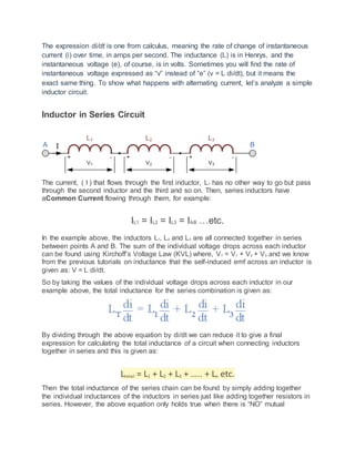
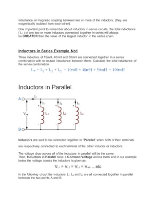
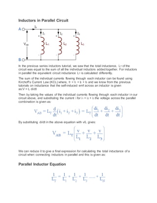
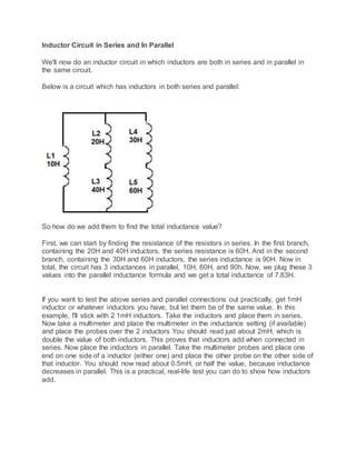
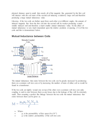
- Inductance is the property of an electrical conductor by which a change in current induces an electromotive force (emf) in both the conductor itself and any nearby conductors.
- Inductors oppose changes in current by inducing a voltage proportional to the rate of change of current in accordance with Lenz's law.
- Inductors can be connected in series or parallel. When in series, their inductances add together to find the total inductance. When in parallel, the reciprocal of their inductances are added together to find the total inductance.
- Mutual inductance is the induction of an emf in one coil due to a changing current in another nearby coil due to their
Malaysia SPM syllabus Physics Chapter 7 Part 4: Electromotive force and internal resistance
Also available for hire!
Contact us for your presentation design needs: lesson / teaching, wedding, seminar, workshop, client pitch etc.
Presentation on Electromagnetic Induction.
Physics two presentation of CSE dept. Southeast University.
PPTX slides made by Saleh Ibne Omar.
December 2017.
This Presentation gives a basic idea about Electromagnetic induction,Faraday's Law ,Lenz's law and the application of Electromagnetic Induction. I included some real life examples of electromagnetic induction also. I hope everyone will like it
Current and Electricity for class 10.pdfJackHassan2
Download our comprehensive Class 10 Current and Electricity PDF guide to master the fundamentals of electrical circuits, current flow, and key concepts in this critical science topic. This PDF provides clear explanations, diagrams, and practice questions to enhance your understanding and preparation. Covering the essential curriculum, it's an invaluable resource for students aiming for excellence in their science studies.
Ekeeda Provides Online Video Lectures, Tutorials & Engineering Courses Available for Top-Tier Universities in India. Lectures from Highly Trained & Experienced Faculty!
Ekeeda - First Year Enginering - Basic Electrical EngineeringEkeedaPvtLtd
The First Year engineering course seems more like an extension of the subjects that students have learned in their 12th class. Subjects like Engineering Physics, Chemistry, and Mathematics, are incorporated into the curriculum. Students will learn about some of the engineering subjects in this first year, and these subjects are similar to all the branches. Everyone will learn some basics related to the other streams in their first year. Ekeeda offers Online First Year Engineering Courses for all the Subjects as per the Syllabus.
CFD Simulation of By-pass Flow in a HRSG module by R&R Consult.pptxR&R Consult
CFD analysis is incredibly effective at solving mysteries and improving the performance of complex systems!
Here's a great example: At a large natural gas-fired power plant, where they use waste heat to generate steam and energy, they were puzzled that their boiler wasn't producing as much steam as expected.
R&R and Tetra Engineering Group Inc. were asked to solve the issue with reduced steam production.
An inspection had shown that a significant amount of hot flue gas was bypassing the boiler tubes, where the heat was supposed to be transferred.
R&R Consult conducted a CFD analysis, which revealed that 6.3% of the flue gas was bypassing the boiler tubes without transferring heat. The analysis also showed that the flue gas was instead being directed along the sides of the boiler and between the modules that were supposed to capture the heat. This was the cause of the reduced performance.
Based on our results, Tetra Engineering installed covering plates to reduce the bypass flow. This improved the boiler's performance and increased electricity production.
It is always satisfying when we can help solve complex challenges like this. Do your systems also need a check-up or optimization? Give us a call!
Work done in cooperation with James Malloy and David Moelling from Tetra Engineering.
More examples of our work https://www.r-r-consult.dk/en/cases-en/
Cosmetic shop management system project report.pdfKamal Acharya
Buying new cosmetic products is difficult. It can even be scary for those who have sensitive skin and are prone to skin trouble. The information needed to alleviate this problem is on the back of each product, but it's thought to interpret those ingredient lists unless you have a background in chemistry.
Instead of buying and hoping for the best, we can use data science to help us predict which products may be good fits for us. It includes various function programs to do the above mentioned tasks.
Data file handling has been effectively used in the program.
The automated cosmetic shop management system should deal with the automation of general workflow and administration process of the shop. The main processes of the system focus on customer's request where the system is able to search the most appropriate products and deliver it to the customers. It should help the employees to quickly identify the list of cosmetic product that have reached the minimum quantity and also keep a track of expired date for each cosmetic product. It should help the employees to find the rack number in which the product is placed.It is also Faster and more efficient way.
Student information management system project report ii.pdfKamal Acharya
Our project explains about the student management. This project mainly explains the various actions related to student details. This project shows some ease in adding, editing and deleting the student details. It also provides a less time consuming process for viewing, adding, editing and deleting the marks of the students.
TECHNICAL TRAINING MANUAL GENERAL FAMILIARIZATION COURSEDuvanRamosGarzon1
AIRCRAFT GENERAL
The Single Aisle is the most advanced family aircraft in service today, with fly-by-wire flight controls.
The A318, A319, A320 and A321 are twin-engine subsonic medium range aircraft.
The family offers a choice of engines
Hybrid optimization of pumped hydro system and solar- Engr. Abdul-Azeez.pdffxintegritypublishin
Advancements in technology unveil a myriad of electrical and electronic breakthroughs geared towards efficiently harnessing limited resources to meet human energy demands. The optimization of hybrid solar PV panels and pumped hydro energy supply systems plays a pivotal role in utilizing natural resources effectively. This initiative not only benefits humanity but also fosters environmental sustainability. The study investigated the design optimization of these hybrid systems, focusing on understanding solar radiation patterns, identifying geographical influences on solar radiation, formulating a mathematical model for system optimization, and determining the optimal configuration of PV panels and pumped hydro storage. Through a comparative analysis approach and eight weeks of data collection, the study addressed key research questions related to solar radiation patterns and optimal system design. The findings highlighted regions with heightened solar radiation levels, showcasing substantial potential for power generation and emphasizing the system's efficiency. Optimizing system design significantly boosted power generation, promoted renewable energy utilization, and enhanced energy storage capacity. The study underscored the benefits of optimizing hybrid solar PV panels and pumped hydro energy supply systems for sustainable energy usage. Optimizing the design of solar PV panels and pumped hydro energy supply systems as examined across diverse climatic conditions in a developing country, not only enhances power generation but also improves the integration of renewable energy sources and boosts energy storage capacities, particularly beneficial for less economically prosperous regions. Additionally, the study provides valuable insights for advancing energy research in economically viable areas. Recommendations included conducting site-specific assessments, utilizing advanced modeling tools, implementing regular maintenance protocols, and enhancing communication among system components.
COLLEGE BUS MANAGEMENT SYSTEM PROJECT REPORT.pdfKamal Acharya
The College Bus Management system is completely developed by Visual Basic .NET Version. The application is connect with most secured database language MS SQL Server. The application is develop by using best combination of front-end and back-end languages. The application is totally design like flat user interface. This flat user interface is more attractive user interface in 2017. The application is gives more important to the system functionality. The application is to manage the student’s details, driver’s details, bus details, bus route details, bus fees details and more. The application has only one unit for admin. The admin can manage the entire application. The admin can login into the application by using username and password of the admin. The application is develop for big and small colleges. It is more user friendly for non-computer person. Even they can easily learn how to manage the application within hours. The application is more secure by the admin. The system will give an effective output for the VB.Net and SQL Server given as input to the system. The compiled java program given as input to the system, after scanning the program will generate different reports. The application generates the report for users. The admin can view and download the report of the data. The application deliver the excel format reports. Because, excel formatted reports is very easy to understand the income and expense of the college bus. This application is mainly develop for windows operating system users. In 2017, 73% of people enterprises are using windows operating system. So the application will easily install for all the windows operating system users. The application-developed size is very low. The application consumes very low space in disk. Therefore, the user can allocate very minimum local disk space for this application.
Democratizing Fuzzing at Scale by Abhishek Aryaabh.arya
Presented at NUS: Fuzzing and Software Security Summer School 2024
This keynote talks about the democratization of fuzzing at scale, highlighting the collaboration between open source communities, academia, and industry to advance the field of fuzzing. It delves into the history of fuzzing, the development of scalable fuzzing platforms, and the empowerment of community-driven research. The talk will further discuss recent advancements leveraging AI/ML and offer insights into the future evolution of the fuzzing landscape.
Forklift Classes Overview by Intella PartsIntella Parts
Discover the different forklift classes and their specific applications. Learn how to choose the right forklift for your needs to ensure safety, efficiency, and compliance in your operations.
For more technical information, visit our website https://intellaparts.com
About
Indigenized remote control interface card suitable for MAFI system CCR equipment. Compatible for IDM8000 CCR. Backplane mounted serial and TCP/Ethernet communication module for CCR remote access. IDM 8000 CCR remote control on serial and TCP protocol.
• Remote control: Parallel or serial interface.
• Compatible with MAFI CCR system.
• Compatible with IDM8000 CCR.
• Compatible with Backplane mount serial communication.
• Compatible with commercial and Defence aviation CCR system.
• Remote control system for accessing CCR and allied system over serial or TCP.
• Indigenized local Support/presence in India.
• Easy in configuration using DIP switches.
Technical Specifications
Indigenized remote control interface card suitable for MAFI system CCR equipment. Compatible for IDM8000 CCR. Backplane mounted serial and TCP/Ethernet communication module for CCR remote access. IDM 8000 CCR remote control on serial and TCP protocol.
Key Features
Indigenized remote control interface card suitable for MAFI system CCR equipment. Compatible for IDM8000 CCR. Backplane mounted serial and TCP/Ethernet communication module for CCR remote access. IDM 8000 CCR remote control on serial and TCP protocol.
• Remote control: Parallel or serial interface
• Compatible with MAFI CCR system
• Copatiable with IDM8000 CCR
• Compatible with Backplane mount serial communication.
• Compatible with commercial and Defence aviation CCR system.
• Remote control system for accessing CCR and allied system over serial or TCP.
• Indigenized local Support/presence in India.
Application
• Remote control: Parallel or serial interface.
• Compatible with MAFI CCR system.
• Compatible with IDM8000 CCR.
• Compatible with Backplane mount serial communication.
• Compatible with commercial and Defence aviation CCR system.
• Remote control system for accessing CCR and allied system over serial or TCP.
• Indigenized local Support/presence in India.
• Easy in configuration using DIP switches.
Industrial Training at Shahjalal Fertilizer Company Limited (SFCL)MdTanvirMahtab2
This presentation is about the working procedure of Shahjalal Fertilizer Company Limited (SFCL). A Govt. owned Company of Bangladesh Chemical Industries Corporation under Ministry of Industries.
Industrial Training at Shahjalal Fertilizer Company Limited (SFCL)
Inductance and Inductor
1. In electromagnetism and electronics, inductance is the property of an electrical
conductor by which a change in current through it induces an electromotive force in both
the conductor itself[ and in any nearby conductors by mutual inductance.
The term inductance was coined by Oliver Heaviside in 1886. It is customary to use the
symbol L for inductance, in honour of the physicist Heinrich Lenz. In the SI system, the
measurement unit for inductance is the henry, with the unit symbol H, named in honor
of Joseph Henry, who discovered inductance independently of, but not before, Faraday.
The henry is a derived unit based on four of the seven base units of the International
System of Units: kilogram (kg), meter (m),second (s), and ampere (A). Expressed in
combinations of SI units, the henry is:[4]
where
Wb = weber,
T = tesla,
J = joule,
m = meter,
s = second,
A = ampere,
V = volt,
C = coulomb,
F = farad,
Hz = hertz,
Ω = ohm
Inductors do not behave the same as resistors. Whereas resistors simply oppose the
flow of electrons through them (by dropping a voltage directly proportional to the
current), inductors oppose changes in current through them, by dropping a voltage
directly proportional to the rate of change of current. In accordance with Lenz’s Law,
this induced voltage is always of such a polarity as to try to maintain current at its
present value. That is, if current is increasing in magnitude, the induced voltage will
“push against” the electron flow; if current is decreasing, the polarity will reverse and
“push with” the electron flow to oppose the decrease. This opposition to current
change is called reactance, rather than resistance.
Expressed mathematically, the relationship between the voltage dropped across the
inductor and rate of current change through the inductor is as such:
2. The expression di/dt is one from calculus, meaning the rate of change of instantaneous
current (i) over time, in amps per second. The inductance (L) is in Henrys, and the
instantaneous voltage (e), of course, is in volts. Sometimes you will find the rate of
instantaneous voltage expressed as “v” instead of “e” (v = L di/dt), but it means the
exact same thing. To show what happens with alternating current, let’s analyze a simple
inductor circuit.
Inductor in Series Circuit
The current, ( I ) that flows through the first inductor, L1 has no other way to go but pass
through the second inductor and the third and so on. Then, series inductors have
aCommon Current flowing through them, for example:
IL1 = IL2 = IL3 = IAB …etc.
In the example above, the inductors L1, L2 and L3 are all connected together in series
between points A and B. The sum of the individual voltage drops across each inductor
can be found using Kirchoff’s Voltage Law (KVL) where, VT = V1 + V2 + V3 and we know
from the previous tutorials on inductance that the self-induced emf across an inductor is
given as: V = L di/dt.
So by taking the values of the individual voltage drops across each inductor in our
example above, the total inductance for the series combination is given as:
By dividing through the above equation by di/dt we can reduce it to give a final
expression for calculating the total inductance of a circuit when connecting inductors
together in series and this is given as:
Ltotal = L1 + L2 + L3 + ….. + Ln etc.
Then the total inductance of the series chain can be found by simply adding together
the individual inductances of the inductors in series just like adding together resistors in
series. However, the above equation only holds true when there is “NO” mutual
3. inductance or magnetic coupling between two or more of the inductors, (they are
magnetically isolated from each other).
One important point to remember about inductors in series circuits, the total inductance
( LT ) of any two or more inductors connected together in series will always
be GREATER than the value of the largest inductor in the series chain.
Inductors in Series Example No1
Three inductors of 10mH, 40mH and 50mH are connected together in a series
combination with no mutual inductance between them. Calculate the total inductance of
the series combination.
Inductors in Parallel
Inductors are said to be connected together in “Parallel” when both of their terminals
are respectively connected to each terminal of the other inductor or inductors.
The voltage drop across all of the inductors in parallel will be the same.
Then, Inductors in Parallel have a Common Voltage across them and in our example
below the voltage across the inductors is given as:
VL1 = VL2 = VL3 = VAB …etc
In the following circuit the inductors L1, L2 and L3 are all connected together in parallel
between the two points A and B.
4. Inductors in Parallel Circuit
In the previous series inductors tutorial, we saw that the total inductance, LT of the
circuit was equal to the sum of all the individual inductors added together. For inductors
in parallel the equivalent circuit inductance LT is calculated differently.
The sum of the individual currents flowing through each inductor can be found using
Kirchoff’s Current Law (KCL) where, IT = I1 + I2 + I3 and we know from the previous
tutorials on inductance that the self-induced emf across an inductor is given
as:V = L di/dt
Then by taking the values of the individual currents flowing through each inductor in our
circuit above, and substituting the current i for i1 + i2 + i3 the voltage across the parallel
combination is given as:
By substituting di/dt in the above equation with v/L gives:
We can reduce it to give a final expression for calculating the total inductance of a
circuit when connecting inductors in parallel and this is given as:
Parallel Inductor Equation
5. Here, like the calculations for parallel resistors, the reciprocal ( 1/Ln ) value of the
individual inductances are all added together instead of the inductances themselves.
But again as with series connected inductances, the above equation only holds true
when there is “NO” mutual inductance or magnetic coupling between two or more of the
inductors, (they are magnetically isolated from each other). Where there is coupling
between coils, the total inductance is also affected by the amount of coupling.
This method of calculation can be used for calculating any number of individual
inductances connected together within a single parallel network. If however, there are
only two individual inductors in parallel then a much simpler and quicker formula can be
used to find the total inductance value, and this is:
One important point to remember about inductors in parallel circuits, the total
inductance ( LT ) of any two or more inductors connected together in parallel will always
be LESS than the value of the smallest inductance in the parallel chain.
Inductors in Parallel Example No1
Three inductors of 60mH, 120mH and 75mH respectively, are connected together in a
parallel combination with no mutual inductance between them. Calculate the total
inductance of the parallel combination in millihenries.
6. Inductor Circuit in Series and In Parallel
We'll now do an inductor circuit in which inductors are both in series and in parallel in
the same circuit.
Below is a circuit which has inductors in both series and parallel:
So how do we add them to find the total inductance value?
First, we can start by finding the resistance of the resistors in series. In the first branch,
containing the 20H and 40H inductors, the series resistance is 60H. And in the second
branch, containing the 30H and 60H inductors, the series inductance is 90H. Now in
total, the circuit has 3 inductances in parallel, 10H, 60H, and 90h. Now, we plug these 3
values into the parallel inductance formula and we get a total inductance of 7.83H.
If you want to test the above series and parallel connections out practically, get 1mH
inductor or whatever inductors you have, but let them be of the same value. In this
example, I'll stick with 2 1mH inductors. Take the inductors and place them in series.
Now take a multimeter and place the multimeter in the inductance setting (if available)
and place the probes over the 2 inductors You should read just about 2mH, which is
double the value of both inductors. This proves that inductors add when connected in
series. Now place the inductors in parallel. Take the multimeter probes and place one
end on one side of a inductor (either one) and place the other probe on the other side of
that inductor. You should now read about 0.5mH, or half the value, because inductance
decreases in parallel. This is a practical, real-life test you can do to show how inductors
add.
7. Energy Stored in an Inductor
Suppose that an inductor of inductance is connected to a variable DC
voltage supply. The supply is adjusted so as to increase the current flowing
through the inductor from zero to some final value . As the current through
the inductor is ramped up, an emf is generated, which acts to
oppose the increase in the current. Clearly, work must be done against this
emf by the voltage source in order to establish the current in the inductor. The
work done by the voltage source during a time interval is
(247)
Here, is the instantaneous rate at which the voltage source
performs work. To find the total work done in establishing the final
current in the inductor, we must integrate the above expression. Thus,
(248)
giving
(249)
This energy is actually stored in the magnetic field generated by the current
flowing through the inductor. In a pure inductor, the energy is stored without
loss, and is returned to the rest of the circuit when the current through the
inductor is ramped down, and its associated magnetic field collapses.
Consider a simple solenoid. Equations (244), (246), and (249) can be
combined to give
(250)
8. which reduces to
(251)
This represents the energy stored in the magnetic field of the solenoid.
However, the volume of the field-filled core of the solenoid is , so the
magnetic energy density (i.e., the energy per unit volume) inside the solenoid
is , or
Mutual Inductance
In the previous tutorial we saw that an inductor generates an induced emf within itself as a result
of the changing magnetic field around its own turns.
When this emf is induced in the same circuit in which the current is changing this effect is
called Self-induction, ( L ). However, when the emf is induced into an adjacent coil situated
within the same magnetic field, the emf is said to be induced magnetically, inductively or
by Mutual induction, symbol ( M ). Then when two or more coils are magnetically linked
together by a common magnetic flux they are said to have the property of Mutual Inductance.
Mutual Inductance is the basic operating principal of the transformer, motors, generators and
any other electrical component that interacts with another magnetic field. Then we can define
mutual induction as the current flowing in one coil that induces an voltage in an adjacent coil.
But mutual inductance can also be a bad thing as “stray” or “leakage” inductance from a coil can
interfere with the operation of another adjacent component by means of electromagnetic
induction, so some form of electrical screening to a ground potential may be required.
The amount of mutual inductance that links one coil to another depends very much on the
relative positioning of the two coils. If one coil is positioned next to the other coil so that their
9. physical distance apart is small, then nearly all of the magnetic flux generated by the first coil
will interact with the coil turns of the second coil inducing a relatively large emf and therefore
producing a large mutual inductance value.
Likewise, if the two coils are farther apart from each other or at different angles, the amount of
induced magnetic flux from the first coil into the second will be weaker producing a much
smaller induced emf and therefore a much smaller mutual inductance value. So the effect of
mutual inductance is very much dependant upon the relative positions or spacing, ( S ) of the two
coils and this is demonstrated below.
Mutual Inductance between Coils
The mutual inductance that exists between the two coils can be greatly increased by positioning
them on a common soft iron core or by increasing the number of turns of either coil as would be
found in a transformer.
If the two coils are tightly wound one on top of the other over a common soft iron core unity
coupling is said to exist between them as any losses due to the leakage of flux will be extremely
small. Then assuming a perfect flux linkage between the two coils the mutual inductance that
exists between them can be given as.
Where:
µo is the permeability of free space (4.π.10-7)
µr is the relative permeability of the soft iron core
10. N is in the number of coil turns
A is in the cross-sectional area in m2
l is the coils length in meters
Mutual Induction
Here the current flowing in coil one, L1 sets up a magnetic field around itself with some of these
magnetic field lines passing through coil two, L2 giving us mutual inductance. Coil one has a
current of I1 and N1 turns while, coil two has N2 turns. Therefore, the mutual inductance, M12 of
coil two that exists with respect to coil one depends on their position with respect to each other
and is given as:
Likewise, the flux linking coil one, L1 when a current flows around coil two, L2 is exactly the
same as the flux linking coil two when the same current flows around coil one above, then the
mutual inductance of coil one with respect of coil two is defined as M21. This mutual inductance
is true irrespective of the size, number of turns, relative position or orientation of the two coils.
Because of this, we can write the mutual inductance between the two coils as: M12 = M21 = M.
Then we can see that self inductance characterises an inductor as a single circuit element, while
mutual inductance signifies some form of magnetic coupling between two inductors or coils,
depending on their distance and arrangement, an hopefully we remember from our tutorials
on Electromagnets that the self inductance of each individual coil is given as:
and
By cross-multiplying the two equations above, the mutual inductance, M that exists between the
two coils can be expressed in terms of the self inductance of each coil.
11. giving us a final and more common expression for the mutual inductance between the two coils
of:
Mutual Inductance Between Coils
However, the above equation assumes zero flux leakage and 100% magnetic coupling between
the two coils, L 1 and L 2. In reality there will always be some loss due to leakage and position, so
the magnetic coupling between the two coils can never reach or exceed 100%, but can become
very close to this value in some special inductive coils.
If some of the total magnetic flux links with the two coils, this amount of flux linkage can be
defined as a fraction of the total possible flux linkage between the coils. This fractional value is
called the coefficient of coupling and is given the letter k.