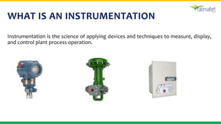
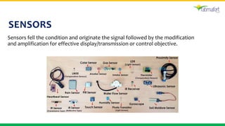
© Fatimafert Ltd.
PROCESS
INSTRUMENTATION
AND CONTROL
SYSTEMS
Developed By: Muhammad Yesrub Iqbal
Designation: SH INSTRUMENT
WHAT IS AN INSTRUMENTATION
Instrumentation is the science of applying devices and techniques to measure, display,
and control plant process operation.
OBJECTIVES
 Optimize process efficiency
 Produce a better product at lower cost in less time
 Provide safety systems for personnel, plant and processes
 Increase and control product quality
 Provide reliable data on raw material, product quantities and
 service related to process economics
 Provide timely and efficient control to avoid mishaps and to
equipment and production loss
CONTENTS
 1: Temperature measurement
 2: Pressure measurement
 3: Flow measurement
 4: Level measurement
 5: Analytical measurement
 6: Vibration and speed monitoring system
 7: Process Controller
 8: Final control Elements
 9: Trend recorders and indicators
 10: Alarm Annunciation
 11: Instrument control loops
 12: Smart instrumentation
 13: PLC (programmable Logic
Controller)
 14: DCS (Distributed Control
System)
SENSORS
Sensors fell the condition and originate the signal followed by the modification
and amplification for effective display/transmission or control objective.
TYPICAL COMPONENT OF
INSTRUMENTATION
 Sensor
‘’measures a physical quantity and converts
into a signal’’
 Modifier
‘’change the type of signal’’
 Display Unit
‘’transmitting arrangements’’
FUNCTIONAL ELEMENT OF
INSTRUMENTATION
TEMPERATURE MEASUREMENT
• Temperature is the measure of hotness and
coldness measured on definite scale.
• Temperature is one of the most frequently
measured quantities in a Process Plant. In
fact, in almost every sector, temperature is
one of the key parameters to be measured.
Accurate, measurement of Temperature is
vital to guarantee product quality and
efficiency in manufacturing, processing of
materials, monitoring and health and safety.
TEMPERATURE
MEASURING METHODS
Contact Type Thermometry Non-contact Type Thermometry
PRESSURE MEASUREMENT
Pressure is the force exerted against a given surface
area. Pressure measured in term of the force applied to
an area or in term of height to which pressure will raise
a column of a given liquid.
PRESSURE MEASUREMENT METHODS
 Mechanical pressure transducers
Liquid column elements
Elastic elements
 Electrical pressure transducers
Strain gauge, Resistance
Force balance (oscillator)
Magnetic, Capacitance
FLOW MEASUREMENT
Flow is fluid in motion. Fluids include liquid, air, gases and steam.
FLOW MEASUREMENT
METHODS
 Differential head type
 Variable area type
 Displacement
 Velocity meter
 Mass flow meter
LEVEL MEASUREMENT
Level is the height of liquid or solid contained in a vessel above a reference or
datum line.
LEVEL MEASUREMENT METHODS
 Direct
Visual indication
Float
Electrical conductivity
 Inferential
Displacement (Buoyancy)
Hydrostatic
Electrical Capacitance
Radiation
ANALYTICAL MEASUREMENT
Proper analytical control system ensure product quality through out
all phases of process.
ANALYTICAL MEASURING INSTRUMENTS
 Methane analyzer (IR type)
 CO/CO2 analyzer
 Hydrogen analyzer
 Conductivity meter
 CO2 Analyzer
 Moisture analyzer
 Oxygen analyzer
 pH meter
 Silica analyzer
VIBRATION AND SPEED MONITORING
SYSTEM
Objectives
 The physical safety of plant personnel and the
potential damage to plant equipment's
surrounding the given machine.
 The expense of making mechanical repairing
in term of both material (replacement parts)
and time (labor).
 Usually the highest Dollar value, the expense
of downtime or outage due to a machinery
failure.
DYNAMIC MOTION (VIBRATION)
PARAMETERS
 Amplitude
 Frequency
 Phase angle
PROXIMITY
MEASUREMENT
CONTROLLER
Controller is a device which monitors and affects the operational conditions of a
given dynamical system. The operational conditions are typically referred to as
output variables of the system which can be affected by adjusting certain input
variables.
DESIGNING CONTROL SYSTEM
Design/choose
the controller
Choose the
control
configuration
Select The
manipulated
variables(utility/pr
ocess)
Select The
measurement
variables(flow,
temp.,etc)
Define The
Philosophy
Design
MIMO(multiple
input output
system)
FINAL CONTROL ELEMENT
A control valve is the most commonly used final control element which
is used to regulate material flow in a process.
CONTINUED
The control valve mainly has two parts:
1. Actuator (Fail Close/ fail Open)
An actuator is a pneumatic, hydraulic or electrically
powered device which supplies force and motion
to open or close a valve.
1. Body and its internal parts are called trim.
This consists of the internal components of a
valve which modulate the flow of the
controlled fluid.
CONTINUED
TYPE OF CONTROL VALVE
ACTUATOR
INDICATORS
‘’Indicator provides a human readable indication of an instrument
signal.’’
Type of Indicators
 Moveable pointer type
 Movable scale type
 Digital type
ALARM ANNUNCIATION
• Alarm annunciation system used
for abnormal condition of process.
• Warning or call to take the
corrective action.
TYPES OF ALARM
ANNUNCIATOR
 Mechanical type
 Electrical type
 Flag type
 Microprocessor based
 Soft annunciation
PLC(PROGRAMMABLE LOGIC
CONTROLLER)
• Programmable controllers were originally designed to replace relay-
based logic systems and solid-state hard-wired logic control panels.
• Programmable controllers examine the status of inputs and in
response, control some process or machine through outputs.
Combination of input and output data are referred to as logic. Several
logic combinations are usually required to carry out a control plan or
program. This control plan in memory is periodically scanned by the
processor, usually a microprocessor, in a predetermined sequential
order.
COMPONENTS OF A TYPICAL PLC
 Processor
 Power Supply
 Input/Output Modules
 Programming Device
DCS(DISTRIBUTED CONTROL SYSTEM)
• A distributed control system (DCS) is a specially designed
automated control system that consists of geographically
distributed control elements over the plant or control area.
• It differs from the centralized control system(PLC) wherein a
single controller at central location handles the control
function, but in DCS each process element or machine or group
of machines is controlled by a dedicated controller. DCS
consists of a large number of local controllers in various
sections of plant control area and are connected via a high
speed communication network
CONTINUED
HARDWARE OF DCS
 Marshalling cabinet
 FTA (Field Termination Assembly)
 CFA (Card File assembly means PMIO Rack)
 Processor rack
 Server
 Operator station
 Intelligent switch
 Redundant communication network
CONTROL SYSTEM EXAMPLE
 Steam boilers are very common in industry, principally because steam power is so
useful. Common uses for steam in industry include doing mechanical work (e.g. a
steam engine moving some sort of machine), heating, producing vacuums (through
the use of “steam ejectors”), and augmenting chemical processes (e.g. reforming of
natural gas into hydrogen and carbon dioxide).
 The process of converting water into steam is quite simple: heat up the water until it
boils. Anyone who has ever boiled a pot of water for cooking knows how this
process works. Making steam continuously, however, is a little more complicated.
An important variable to measure and control in a continuous boiler is the level of
water in the “steam drum” (the upper vessel in a water-tube boiler). In order to
safely and efficiently produce a continuous flow of steam, we must ensure the
steam drum never runs too low on water, or too high. If there is not enough water in
the drum, the water tubes may run dry and burn through from the heat of the fire. If
there is too much water in the drum, liquid water may be carried along with the flow
of steam, causing problems downstream.
BOILER LEVEL CONTROL
THANK YOU

Introduction to Instrumentation.pptx

  • 1.
    © Fatimafert Ltd. PROCESS INSTRUMENTATION ANDCONTROL SYSTEMS Developed By: Muhammad Yesrub Iqbal Designation: SH INSTRUMENT
  • 3.
    WHAT IS ANINSTRUMENTATION Instrumentation is the science of applying devices and techniques to measure, display, and control plant process operation.
  • 4.
    OBJECTIVES  Optimize processefficiency  Produce a better product at lower cost in less time  Provide safety systems for personnel, plant and processes  Increase and control product quality  Provide reliable data on raw material, product quantities and  service related to process economics  Provide timely and efficient control to avoid mishaps and to equipment and production loss
  • 5.
    CONTENTS  1: Temperaturemeasurement  2: Pressure measurement  3: Flow measurement  4: Level measurement  5: Analytical measurement  6: Vibration and speed monitoring system  7: Process Controller  8: Final control Elements  9: Trend recorders and indicators  10: Alarm Annunciation  11: Instrument control loops  12: Smart instrumentation  13: PLC (programmable Logic Controller)  14: DCS (Distributed Control System)
  • 6.
    SENSORS Sensors fell thecondition and originate the signal followed by the modification and amplification for effective display/transmission or control objective.
  • 7.
    TYPICAL COMPONENT OF INSTRUMENTATION Sensor ‘’measures a physical quantity and converts into a signal’’  Modifier ‘’change the type of signal’’  Display Unit ‘’transmitting arrangements’’
  • 8.
  • 9.
    TEMPERATURE MEASUREMENT • Temperatureis the measure of hotness and coldness measured on definite scale. • Temperature is one of the most frequently measured quantities in a Process Plant. In fact, in almost every sector, temperature is one of the key parameters to be measured. Accurate, measurement of Temperature is vital to guarantee product quality and efficiency in manufacturing, processing of materials, monitoring and health and safety.
  • 10.
    TEMPERATURE MEASURING METHODS Contact TypeThermometry Non-contact Type Thermometry
  • 11.
    PRESSURE MEASUREMENT Pressure isthe force exerted against a given surface area. Pressure measured in term of the force applied to an area or in term of height to which pressure will raise a column of a given liquid.
  • 12.
    PRESSURE MEASUREMENT METHODS Mechanical pressure transducers Liquid column elements Elastic elements  Electrical pressure transducers Strain gauge, Resistance Force balance (oscillator) Magnetic, Capacitance
  • 13.
    FLOW MEASUREMENT Flow isfluid in motion. Fluids include liquid, air, gases and steam.
  • 14.
    FLOW MEASUREMENT METHODS  Differentialhead type  Variable area type  Displacement  Velocity meter  Mass flow meter
  • 15.
    LEVEL MEASUREMENT Level isthe height of liquid or solid contained in a vessel above a reference or datum line.
  • 16.
    LEVEL MEASUREMENT METHODS Direct Visual indication Float Electrical conductivity  Inferential Displacement (Buoyancy) Hydrostatic Electrical Capacitance Radiation
  • 17.
    ANALYTICAL MEASUREMENT Proper analyticalcontrol system ensure product quality through out all phases of process.
  • 18.
    ANALYTICAL MEASURING INSTRUMENTS Methane analyzer (IR type)  CO/CO2 analyzer  Hydrogen analyzer  Conductivity meter  CO2 Analyzer  Moisture analyzer  Oxygen analyzer  pH meter  Silica analyzer
  • 19.
    VIBRATION AND SPEEDMONITORING SYSTEM Objectives  The physical safety of plant personnel and the potential damage to plant equipment's surrounding the given machine.  The expense of making mechanical repairing in term of both material (replacement parts) and time (labor).  Usually the highest Dollar value, the expense of downtime or outage due to a machinery failure.
  • 20.
    DYNAMIC MOTION (VIBRATION) PARAMETERS Amplitude  Frequency  Phase angle
  • 21.
  • 22.
    CONTROLLER Controller is adevice which monitors and affects the operational conditions of a given dynamical system. The operational conditions are typically referred to as output variables of the system which can be affected by adjusting certain input variables.
  • 23.
    DESIGNING CONTROL SYSTEM Design/choose thecontroller Choose the control configuration Select The manipulated variables(utility/pr ocess) Select The measurement variables(flow, temp.,etc) Define The Philosophy Design MIMO(multiple input output system)
  • 24.
    FINAL CONTROL ELEMENT Acontrol valve is the most commonly used final control element which is used to regulate material flow in a process.
  • 25.
    CONTINUED The control valvemainly has two parts: 1. Actuator (Fail Close/ fail Open) An actuator is a pneumatic, hydraulic or electrically powered device which supplies force and motion to open or close a valve. 1. Body and its internal parts are called trim. This consists of the internal components of a valve which modulate the flow of the controlled fluid.
  • 26.
  • 27.
    TYPE OF CONTROLVALVE ACTUATOR
  • 28.
    INDICATORS ‘’Indicator provides ahuman readable indication of an instrument signal.’’ Type of Indicators  Moveable pointer type  Movable scale type  Digital type
  • 29.
    ALARM ANNUNCIATION • Alarmannunciation system used for abnormal condition of process. • Warning or call to take the corrective action.
  • 30.
    TYPES OF ALARM ANNUNCIATOR Mechanical type  Electrical type  Flag type  Microprocessor based  Soft annunciation
  • 31.
    PLC(PROGRAMMABLE LOGIC CONTROLLER) • Programmablecontrollers were originally designed to replace relay- based logic systems and solid-state hard-wired logic control panels. • Programmable controllers examine the status of inputs and in response, control some process or machine through outputs. Combination of input and output data are referred to as logic. Several logic combinations are usually required to carry out a control plan or program. This control plan in memory is periodically scanned by the processor, usually a microprocessor, in a predetermined sequential order.
  • 32.
    COMPONENTS OF ATYPICAL PLC  Processor  Power Supply  Input/Output Modules  Programming Device
  • 33.
    DCS(DISTRIBUTED CONTROL SYSTEM) •A distributed control system (DCS) is a specially designed automated control system that consists of geographically distributed control elements over the plant or control area. • It differs from the centralized control system(PLC) wherein a single controller at central location handles the control function, but in DCS each process element or machine or group of machines is controlled by a dedicated controller. DCS consists of a large number of local controllers in various sections of plant control area and are connected via a high speed communication network
  • 34.
  • 35.
    HARDWARE OF DCS Marshalling cabinet  FTA (Field Termination Assembly)  CFA (Card File assembly means PMIO Rack)  Processor rack  Server  Operator station  Intelligent switch  Redundant communication network
  • 36.
    CONTROL SYSTEM EXAMPLE Steam boilers are very common in industry, principally because steam power is so useful. Common uses for steam in industry include doing mechanical work (e.g. a steam engine moving some sort of machine), heating, producing vacuums (through the use of “steam ejectors”), and augmenting chemical processes (e.g. reforming of natural gas into hydrogen and carbon dioxide).  The process of converting water into steam is quite simple: heat up the water until it boils. Anyone who has ever boiled a pot of water for cooking knows how this process works. Making steam continuously, however, is a little more complicated. An important variable to measure and control in a continuous boiler is the level of water in the “steam drum” (the upper vessel in a water-tube boiler). In order to safely and efficiently produce a continuous flow of steam, we must ensure the steam drum never runs too low on water, or too high. If there is not enough water in the drum, the water tubes may run dry and burn through from the heat of the fire. If there is too much water in the drum, liquid water may be carried along with the flow of steam, causing problems downstream.
  • 37.
  • 38.